


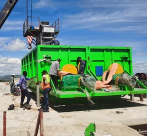


By 2025, Tongli has helped more than 60+ environmental protection companies to establish sludge incineration production lines to help process various sewage sludge and harzardous waste into value added products.
Tongli sludge processing Incinerator rotary kiln is a leading solution for efficient waste treatment, particularly designed to handle a wide range of materials, including medical waste, trash, garbage, and industrial by-products. The incinerator utilizes a rotary kiln, or rotary calciner, which ensures optimal combustion through continuous rotation, promoting thorough and even waste processing. Sludge is burned at high temperature. During the combustion process, organic matter is oxidized and decomposed, and the heat generated is used to maintain the high temperature environment in the kiln. The ashes after combustion can be used as building materials, which has very high economic benefits. This advanced technology allows for the safe and effective disposal of various waste types, including hazardous and non-hazardous materials, while reducing emissions and energy consumption. Whether it's for medical waste, general trash, or industrial waste, the Tongli rotary kiln incinerator stands out as a reliable and eco-friendly choice for modern waste management.
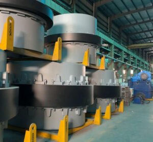
SLUDGE HAZARDOUS WASTE INCINERATOR

"Industrial sludge incineration kiln is designed to treat sludge generated by sewage treatment plants. It reduces sludge volume and secondary pollution through efficient incineration technology to support environmental protection goals."

"Garbage incineration power generation kiln converts urban garbage into energy, using efficient incineration technology, which not only reduces garbage accumulation, but also provides a sustainable solution for energy production."

"Hazardous waste incineration rotary kiln uses high temperature technology to safely treat hazardous waste, effectively reduce harmful gas emissions, ensure complete destruction of waste, and meet environmental protection requirements."

"Medical waste incineration rotary kiln uses strict temperature control and rotation technology to safely and effectively destroy medical waste, ensuring that pathogens and harmful substances are completely eliminated, meeting medical waste treatment standards."
ROTARY CALCINER ADVANTAGES
Large processing capacity: Tongli sludge incineration kiln can process a large amount of sludge, can adapt to the needs of sludge treatment of different scales, and meet the growing sludge production and treatment requirements.
Full combustion: By optimizing the furnace structure and adopting advanced burner and other technologies, the sludge can be fully burned in the kiln, which improves the treatment efficiency and reduces the emission of unburned materials.
Heat recovery and utilization: Some incineration kilns can use the waste heat recovery system to recover and reuse the heat in the flue gas for preheating sludge, generating steam or power generation, etc., which improves the utilization rate of energy and achieves energy conservation and emission reduction.
Efficiently decomposes gases: Secondary combustion chamber is usually equipped with a second combustion chamber, so that harmful gases such as dioxins generated during the combustion process can be further decomposed and burned under high temperature, sufficient oxygen and sufficient residence time, reducing the emission of harmful gases.
Precise temperature control: The temperature in the kiln can be controlled more accurately within a certain range, such as the temperature in the rotary kiln is controlled at 700℃-800℃, so that the drying and combustion processes of the sludge can be carried out stably.
Good fuel adaptability: It can use conventional fuels such as petroleum gas and fuel oil for preheating and auxiliary combustion, and can also use the calorific value of sludge itself for combustion, so as to achieve energy self-sufficiency to a certain extent and reduce operating costs.
Wide range of applications: Tongli incinerator kiln can treat various types of sludge, including sludge from urban domestic sewage plants, sludge from industrial wastewater treatment plants, etc. It has relatively low requirements for the dryness and composition of sludge, and can also treat other solid wastes or hazardous wastes.
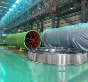
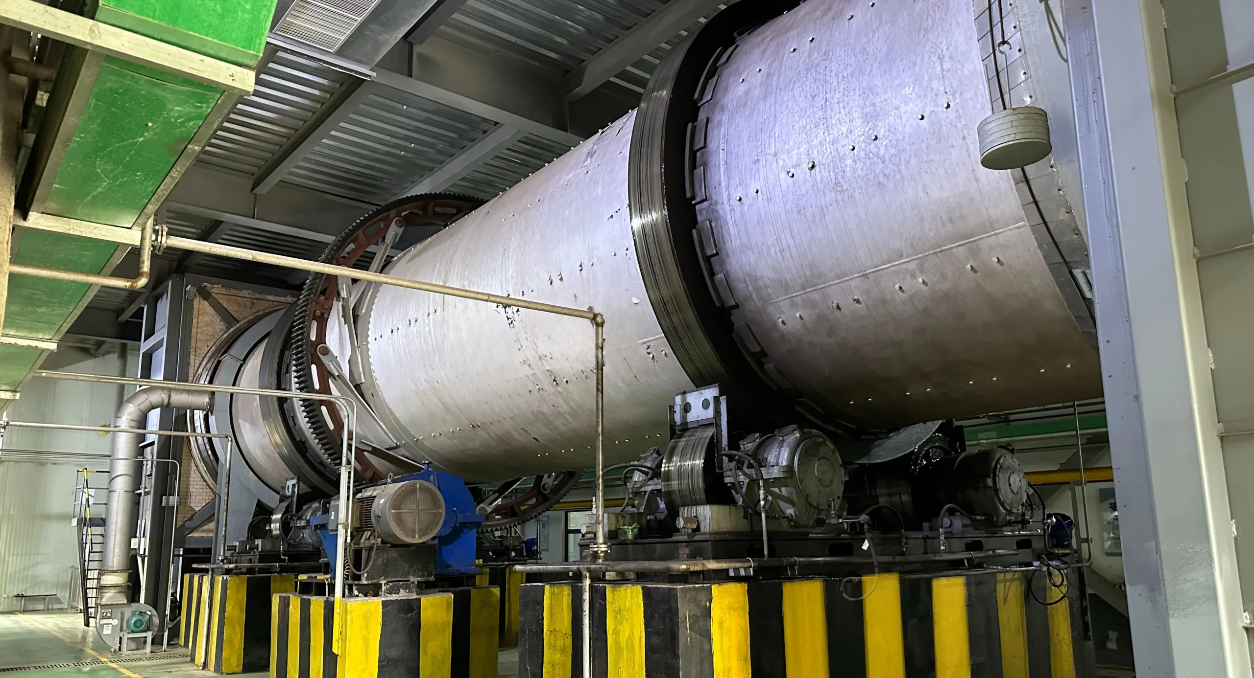
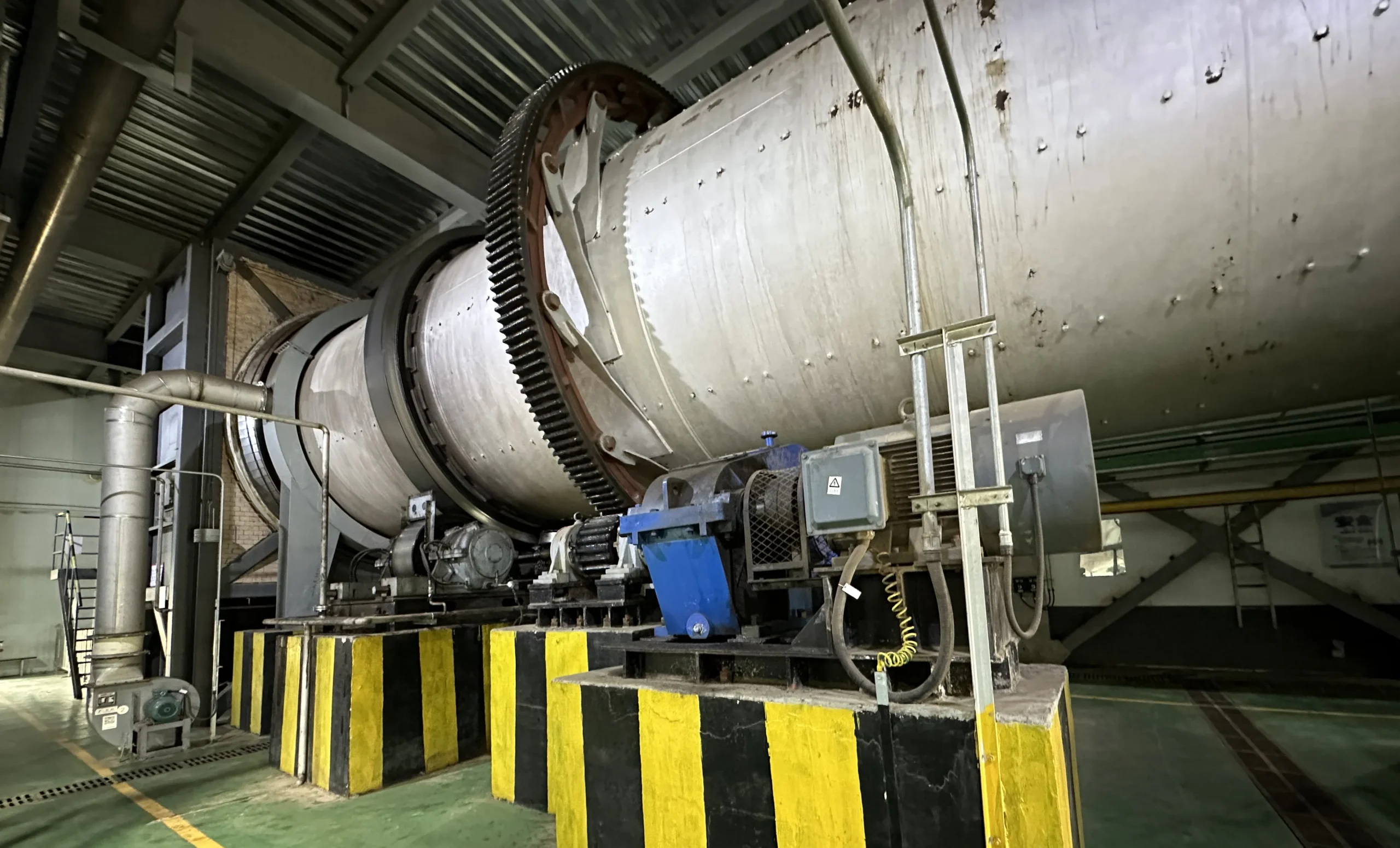
The structure of Tongli rotary kiln is mainly composed of cylinder, refractory materials, transmission device, etc., and key components such as furnace and burner are high temperature resistant materials. By accurately controlling the combustion conditions such as incineration temperature and excess air coefficient, the sludge combustion can be made more complete and efficient, reducing heat loss and improving thermal efficiency.
SLUDGE HAZARDOUS WASTE DISPOSAL PROCESS FLOW
Sludge receiving and storage
Wet sludge with a moisture content of about 80% first enters the first step of the treatment process: weighing. Wet sludge is accurately weighed by a floor scale, which not only helps to count the amount of sludge entering the factory, but also provides a data basis for the subsequent treatment process. After weighing, the wet sludge immediately enters the sludge receiving bin, which plays a role in temporarily storing sludge, ensuring the continuity and stability of the sludge treatment process, and avoiding the impact of unstable sludge supply at the front end on the operation of the entire production line.
Sludge pretreatment
Conditioning and sterilization: The sludge enters the buffer bin to play a conditioning role and then enters the sterilization tank. Sludge sterilizer is added to prevent the sludge from producing foul-smelling gases such as hydrogen sulfide in the subsequent disposal process. Modification and separation: After sterilization, the sludge enters the bacterial floc crushing reactor for modification. The conditioning agent is added to completely inactivate the extracellular polymers in the sludge, reduce the viscosity of the sludge, and facilitate the subsequent organic-inorganic separation and dehydration. Dehydration: The separated organic and inorganic sludge enters the plate and frame dehydration system through a plunger pump. The separated organic sludge is added with a dehydration aid, and after being fully mixed, it enters the organic sludge filter press for dehydration.
Sludge transportation and drying
The wet sludge stored in the sludge receiving bin is transported to the sludge storage bin by the sludge conveying pump. The sludge storage bin further ensures a stable supply of sludge, allowing it to be quantitatively distributed according to the needs of subsequent treatment processes. Then, the sludge is quantitatively transported from the storage bin to the direct drum dryer and auxiliary dryer through the sludge conveying pump.
Sludge incineration
The dried sludge enters the intermediate silo through the conveyor. The intermediate silo plays a role of buffering and uniform distribution, ensuring that the amount of sludge entering the incinerator is stable and uniform. Subsequently, the sludge in the intermediate silo is sent to the incinerator for incineration. In the incinerator, the dry sludge undergoes three key stages: drying, burning and burning. In the rotary kiln incinerator, its main body is a horizontal and rotatable cylindrical cylinder, the outer shell is made of rolled steel plates, lined with refractory materials, and the cylinder has a certain inclination. The sludge enters the kiln from the high end (head) and slowly moves to the tail as the cylinder rotates. The rotation of the kiln allows the sludge to fully contact with the combustion air during the combustion process, completing the entire combustion process. The non-incinerable materials are discharged from the tail of the rotary kiln as slag and enter the slag hopper. These slags can be reused or landfilled according to their composition and properties. The incinerable materials are converted into gaseous form and enter the secondary combustion chamber for further incineration. The high-temperature flue gas generated by the incineration enters the subsequent thermal oil furnace or other heat exchange devices. The combustion temperature of the incinerator is greater than 850℃. Such a high temperature environment can ensure that the organic matter in the sludge is fully burned and decomposed, reducing the residual harmful substances. The fly ash after incineration enters the ash hopper. The fly ash may contain harmful substances such as heavy metals, so it needs to be solidified and stabilized. The treated fly ash can effectively prevent dust from spreading and polluting the environment, and meet the sanitary landfill standards of ordinary solid waste, thereby avoiding secondary pollution to the environment caused by fly ash.
Exhaust tail gas treatment
The 700℃ - 800℃ high-temperature flue gas discharged from the incinerator is used as the drying heat source of the dryer and the heat source of the heat exchanger. The heat exchanger uses waste heat, and the stirring drum dryer does not need to be equipped with an additional heat source. The 200℃ dust-containing gas generated by drying enters the heat exchanger after the dust is recovered by the dust collector, and the carrier gas after auxiliary drying and condensation enters the heat exchanger. After preheating to 500℃, it enters the incinerator for deodorization. Part of the deodorized flue gas returns to the dryer for drying sludge, and the other part enters the tail gas treatment process. The air of the incinerator comes from the suction wind in the upper space of the sludge unloading station. The air containing trace odor enters the incinerator after being preheated by heat exchange. The air preheating reduces the impact of combustion on the furnace body and improves the incineration efficiency. The flue gas of the incinerator and the flue gas of the dryer form a closed recycling system, which fully burns the dust particles in the flue gas and realizes the recycling of heat energy. The flue gas generated by the incinerator is discharged through the chimney after the heat energy is recovered through heat exchange and the dust is collected and the flue gas is treated to meet the standards.
Slag treatment
Slag treatment: The slag after incineration is discharged through the slag discharge port and enters the slag hopper, where it can be further screened, crushed, and then reused as building materials, landscaping, road cushions, and other materials. Fly ash treatment: The fly ash produced by incineration enters the ash hopper, where it is solidified and stabilized. Water and chemicals are added to stir and mix the fly ash, so that pollutants such as heavy metals in the fly ash are stabilized to prevent them from leaching and spreading in the environment. The treated fly ash can meet the sanitary landfill standards of ordinary solid waste and be landfilled, or it can be used as a resource under certain conditions.
Waste disposal Incineration kiln
The main body is a horizontal and rotatable cylindrical shell, the outer shell is made of rolled steel plates and lined with refractory materials; the axis of the cylinder maintains a certain inclination angle with the horizontal plane, and the sludge enters the kiln from the higher end (head) by the feeder, and slowly moves to the tail as the cylinder rotates. The rotation of the kiln allows the material to fully contact with the combustion-supporting air during the combustion process, completing the entire process of drying, burning, and burning, and finally the burnt slag is discharged from the tail. It has strong adaptability to changes in incineration materials, and special garbage with high water content can be burned normally; the incineration materials tumble forward, and the three heat transfer methods of radiation, convection, and conduction coexist in one furnace, with high thermal utilization rate; the warm materials contact high-temperature refractory materials, and the furnace lining is easy to replace with low cost; the transmission mechanism is simple, and the transmission mechanism is outside the kiln shell.
Secondary combustion chamber
In the rotary kiln, the sludge may not be completely burned, and some unburned combustible gas and some unburned materials will be produced. The secondary combustion chamber provides a high temperature, oxygen-rich environment for these substances. The carbon monoxide and dioxins in the flue gas produced by the rotary kiln are decomposed under high temperature and sufficient residence time. The burner sprays high temperature flames and combustion air into the combustion chamber to achieve more complete combustion and reduce pollutants. At the same time, the flue gas direction and velocity are changed through the spoiler, arch wall and retaining wall, and the residence time of the flue gas in the combustion chamber is prolonged. Generally, the residence time of the flue gas in the secondary combustion chamber is required to be greater than 2s, so that the flue gas The harmful substances in the water are fully decomposed at high temperatures. After being processed in the secondary combustion chamber, the unburned substances in the flue gas are basically burned out, the harmful substances are effectively decomposed, and the ash in the flue gas in the rotary kiln incinerator is separated out, reducing the dust removal pressure at the rear end, thereby improving the efficiency of the rotary kiln incinerator. The work efficiency is improved, and then it enters the subsequent waste heat utilization system and tail gas treatment system for further processing. .
VIDEO

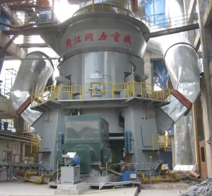
What is a VRM grinding station for slag/clinker/cement?
VRM grinding station can efficiently grind raw materials like limestone and clay into fine powder for cement production.
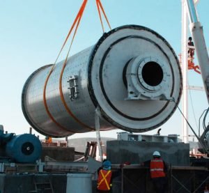
What is a GGBFS cement clinker ball mill?
Designed for high-efficiency grinding of ground granulated blast furnace slag (GGBFS) and clinker

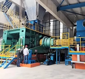
What is a cement grinding plant?
Involves ball mills, vertical mills, classifier to achieve the desired fineness and quality.

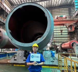
What is cement clinker calcination rotary kiln?
Used to heat raw materials like limestone, clay, gypsum to 1400-1600°C to produce cement clinker.
WHY CHOOSE US
"Our company has been handling hazardous waste for a long time. The temperature of the tongli hazardous waste kiln is stable, the waste in the secondary combustion chamber is completely incinerated, and the harmful gas emissions meet the standards and comply with environmental protection regulations. We strongly recommend it to companies in the same industry."

CFO
"The incineration effect of Tongli's sludge industrial incineration kiln is remarkable, the sludge volume is reduced by more than 90%, and there is no secondary pollution. The equipment runs stably, saving us a lot of operating costs, and the odor control is also very good because we are close to residents. The area is very close. "

CEO
"We have very high requirements for waste incineration equipment. Tongli's medical waste incineration rotary kiln has precise temperature control, complete waste incineration, and can effectively kill pathogens, fully meeting the high standards for medical waste treatment."

CEO
"We have been using Tongli's waste-to-energy kiln in our waste incineration plant for some time and the equipment has performed very well. By converting waste into energy through incineration, we not only reduce the amount of landfill, but also provide renewable electricity for the local area. The equipment is stable and reliable, and the pollution emissions are far below the industry standard."
CEO
FAQ
The outlet temperature of the sludge incineration rotary kiln is 800-850℃. After the flue gas enters the secondary combustion chamber, secondary air is injected tangentially around the secondary combustion chamber, forming a strong vortex field in the secondary combustion chamber, and the combustible components in the flue gas can be fully burned. At the same time, the secondary combustion chamber adopts a unique structural design to make the secondary combustion chamber also have a cyclone dust removal function. The flue gas outlet temperature of the secondary combustion chamber is greater than 1100℃, and the flue gas stays in the high temperature zone for more than 2 seconds, ensuring that the harmful components in the flue gas, including dioxins, are completely decomposed and meet the requirements for the incineration of hazardous waste. Solid (hazardous) waste is fed into the rotary kiln body through the feeding mechanism for high-temperature incineration. After high-temperature incineration, the material is burned into high-temperature flue gas and ash. The rotation speed of the rotary kiln can be adjusted. Maintaining a stable slag layer of about 50mm thick can protect the refractory layer. Its operating temperature should be controlled at around 850℃. High-temperature flue gas and ash enter the secondary combustion chamber from the kiln tail, and the incineration ash enters the slag discharger from the kiln tail and is regularly sent to the stabilization/solidification workshop for treatment.
1. Municipal sludge: It mainly comes from urban sewage treatment plants and is solid sediment produced in the process of treating domestic sewage. It usually contains high organic matter, such as microbial cells, organic debris, etc. It also contains rich nutrients such as nitrogen, phosphorus, potassium, and a certain amount of heavy metals, pathogenic microorganisms and other harmful substances. The water content is generally high, up to 99% or more, in a colloidal state, with a certain viscosity and fluidity, and it is easy to rot and stink. If it is not handled properly, it will cause secondary pollution to the environment. Treatment effect: Through the treatment of sludge incineration kiln, it can effectively destroy the organic matter in it, kill pathogens, and achieve reduction, harmlessness and stabilization. The volume of the residue after incineration is greatly reduced, generally only about 10% of the original volume, and it can effectively control the leaching of heavy metals and reduce the harm to the environment.
2. Papermaking sludge: It is produced in the wastewater treatment process of the papermaking industry. The main components include fine fibers, lignin, fillers, and chemical agents added in the papermaking process. It has a high organic matter content and usually contains a certain amount of heavy metal ions, such as mercury, cadmium, lead, etc., and due to different papermaking processes, the properties of sludge will also vary. Some papermaking sludge is acidic, some is alkaline, and has a certain corrosiveness. Treatment effect: The sludge incineration kiln can completely burn and decompose the organic matter in the papermaking sludge, converting it into harmless substances such as carbon dioxide and water. At the same time, high temperature can fix heavy metals in the incineration residue, reduce its leaching risk, and achieve harmless treatment.
3. Printing and dyeing sludge is produced after the treatment of wastewater in the printing and dyeing industry. It contains a large amount of organic pollutants such as dyes, auxiliaries, and fiber scraps. It has complex composition, dark color, and high chemical oxygen demand (COD) and biochemical oxygen demand (BOD). In addition, printing and dyeing sludge may also contain heavy metal ions and difficult-to-degrade organic compounds, such as aromatic amines, which have certain toxicity and bioaccumulation. Treatment effect: In the sludge incineration kiln, high-temperature combustion can completely decompose the organic pollutants in the printing and dyeing sludge and convert them into harmless gases and ashes. At the same time, through a reasonable flue gas treatment system, harmful gases such as sulfur dioxide and nitrogen oxides generated during the combustion process can be effectively removed to reduce pollution to the environment.
4. Electroplating sludge: It is produced during the treatment of electroplating industrial wastewater. It is rich in heavy metal ions, such as chromium, nickel, copper, zinc, etc., with high content and strong toxicity and corrosiveness. The water content of electroplating sludge is relatively low, but due to the presence of heavy metals, it is extremely harmful to the environment and is a hazardous waste. Treatment effect: When treating electroplating sludge, the sludge incineration kiln needs to be equipped with special flue gas treatment and residue treatment facilities. High-temperature incineration can stabilize heavy metal ions in the residue and reduce their leaching toxicity. At the same time, the flue gas treatment system removes heavy metal volatiles and harmful gases generated during the combustion process to ensure that the emission meets environmental protection standards.
5. Metal processing sludge: Wastewater treatment from the metal processing industry, such as machinery manufacturing, metal surface treatment, etc., mainly contains organic and inorganic pollutants such as metal debris, cutting fluid, lubricating oil, and rust inhibitors. Among them, the content of heavy metals is relatively high, such as iron, copper, zinc, lead, etc., and the organic composition is complex, and may contain difficult-to-degrade organic compounds. The particles of metal processing sludge are fine, black or gray, and have a certain viscosity. Treatment effect: In the sludge incineration kiln, high temperature can cause the organic matter to burn and decompose, and the heavy metals are solidified in the residue. Through subsequent residue treatment and resource recycling, metal recovery and harmless treatment of sludge can be achieved, reducing environmental pollution and waste of resources.
6. River and lake sludge: Produced during the dredging of rivers and lakes and the improvement of water environment. Composition and characteristics: The composition is relatively complex, generally with inorganic matter as the main component, but also contains a certain amount of organic matter, such as rotten aquatic plants, microorganisms, etc. Its particles are fine, the specific gravity liquid limit is relatively small, and the content of harmful and toxic substances is usually less, but it may contain some heavy metals and organic pollutants, such as mercury, cadmium, polychlorinated biphenyls, etc., and its content varies depending on the degree of pollution of lakes and rivers. Treatment effect: Through the treatment of sludge incineration kiln, organic matter and some harmful pollutants can be effectively removed, the volume of sludge can be reduced, and the harm to the environment can be reduced. At the same time, the residue after incineration can be further treated and utilized, such as as raw materials for building materials.
7. Chemical sludge: It is the sludge produced by treating water or wastewater with inorganic coagulants (coagulants) in the process of sewage treatment, using chemical enhanced primary treatment or tertiary treatment methods. It has a low organic content and mainly includes coagulants, coagulants and their difficult-to-biodegrade organic matter, colloids and plant nutrients such as nitrogen and phosphorus. It is gel-like, light and fluffy, with a high water content, a fractal structure, and a branch and mesh structure similar to fluff in appearance. It has poor fluidity, a relatively large density, and is stable and not easy to decompose. However, as the pH value changes, heavy metal ions may be dissolved. Treatment effect: In the sludge incineration kiln, although its organic content is low, it can be completely decomposed by high temperature, and the heavy metal ions in it are stabilized in the residue to reduce its potential harm to the environment.
Landfill leachate sludge: A certain amount of sludge is produced during the treatment of landfill leachate, which contains a large amount of harmful substances such as organic matter and heavy metals. Incineration through sludge incineration kilns can effectively eliminate these harmful substances and reduce environmental pollution. At the same time, the heat generated by incineration can be used to reduce the operating costs of landfills.
8. Pharmaceutical sludge: The sludge in the pharmaceutical industry may contain some residual drug components and organic matter, which has high biological toxicity and environmental risks. Sludge incineration kilns can thoroughly incinerate pharmaceutical sludge, eliminate harmful substances in it, and protect the environment and public health.
1. Structural differences:
Main structure of sludge incineration rotary kiln: The main body is a horizontal and rotatable cylindrical cylinder, and the outer shell is usually made of rolled steel plates. The axis of the cylinder maintains a certain inclination with the horizontal plane, generally about 2% - 5%. The diameter of a rotary kiln cylinder may be between 1.5 and 4 meters, and the length range from 10 to 60 meters. The inner lining is refractory to protect the cylinder and withstand high temperatures. The thickness of the refractory material is generally 200-300mm, and its material is selected according to the incineration temperature and the nature of the sludge, such as high-aluminum refractory material. The transmission device is located outside the kiln shell, and the cylinder is driven to rotate through components such as motors, reducers, and gears. The transmission mechanism is relatively simple and easy to maintain the equipment. For example, the motor power depends on the size and processing capacity of the rotary kiln, which may be around 15-100kW. Feeding and discharging device: The sludge enters the kiln from the high end (head) through the feeder, and slowly moves to the tail as the cylinder rotates. The discharge port is at the tail end, and the burnt slag is discharged from here. The feeding device must ensure uniform feeding of sludge, and the discharging device must be able to smoothly discharge slag and prevent hot gas leakage.
Fluidized bed incinerator structure: mainly composed of wind box, middle section and suction hood. The wind box is used to distribute the circulating gas to different areas of the fluidized bed device through the gas distribution plate. The gas distribution plate is a key component, and its parameters such as opening rate and pore size affect the fluidization quality. A heat exchanger is provided in the middle section to transfer heat to the sludge and dry it. The bed of the fluidized bed incinerator is generally a vertical or slightly inclined container filled with inert particles (such as quartz sand, etc.) as a fluidizing medium, and the particle diameter is usually between 0.5-3mm. Fluidization system: including fans, pipes, etc., used to provide gas to fluidize the bed particles. The fluidizing gas is usually air or inert gas, and the fluidizing speed is generally 1-3m/s to ensure that the sludge can be fully fluidized in the bed and fully contact with the heat medium and oxygen. Feeding and discharging system: The feeding system must ensure that the sludge enters the fluidized bed evenly to prevent local overheating or uneven fluidization. The discharging system must be able to discharge the residue and fly ash after combustion in time, and prevent the leakage of unburned materials.
2. Functional differences:
Sludge incineration rotary kiln: The sludge rolls forward in the kiln as the cylinder rotates, and is fully in contact with the combustion-supporting air during the combustion process, completing the entire process of drying, burning, and burning. Due to its rotating motion, it has strong adaptability to changes in the incineration materials, and special garbage with high water content can be burned normally, and even some blocky and viscous sludge can be effectively treated. There is a secondary combustion chamber. During the slow rotation of the furnace body, the waste in the furnace is decomposed and gasified into combustible gas for combustion, and complete combustion is achieved in the secondary combustion chamber, ensuring the high temperature required for the decomposition of harmful substances, so that the flue gas has enough residence time and reduces harmful gas emissions. Heat utilization: The high-temperature flue gas generated by incineration can enter the subsequent thermal oil furnace or other heat exchange devices for heat recovery, which is used for sludge drying or other process links that require thermal energy. For example, the flue gas temperature can reach 800-1000℃, and the heat can be transferred to thermal oil or air through the heat exchanger. Processing range: It can not only process sludge, but also other solid wastes, such as industrial waste residues, etc., with a wide range of applicability.
Fluidized bed incinerator: Sludge burns in a fluidized state. Due to the full mixing and contact between the sludge, fluidizing medium (such as quartz sand) and air, the combustion efficiency is high. Its combustion process is relatively uniform, which can enable the sludge to be completely burned at a relatively low excess air coefficient, reducing the flue gas volume and the burden of subsequent treatment. There are certain requirements for the particle size and moisture content of the sludge. Generally, the sludge needs to be pretreated first to achieve a suitable particle size (such as less than 10mm) and moisture content (such as less than 60%) to ensure good fluidization effect and combustion performance. Heat utilization: The heat generated by combustion can also be used to transfer heat to other media through a heat exchanger, such as for preheating air, generating steam, etc. The heat exchange efficiency of the fluidized bed incinerator is relatively high, because the contact between the sludge and the heat exchange surface is relatively sufficient, and the heat can be effectively recovered. Processing range: It is mainly used to treat sludge with small particle size and good fluidity. For some sludge with large viscosity and blocky shape, special pretreatment is required to effectively treat it.
3. Prices difference:
The rotary kiln body is expensive due to its large size and relatively complex lining structure. Generally speaking, the price of a medium-sized (processing capacity of 10-50t/h) rotary kiln equipment may be around 6-8 million yuan, which is about 840,000 to 1.12 million US dollars. The cost of its transmission device, feeding and discharging device and other components also accounts for a certain proportion. Installation cost: Due to the large size and heavy weight of the rotary kiln, the installation requires professional lifting equipment and installation team, and the installation cost is relatively high. Including the cost of infrastructure, equipment hoisting, commissioning, etc., it may be around 500,000 to 2 million yuan, which is about 70,000 to 280,000 US dollars. Refractory cost: The quality and thickness of the lining refractory material have a great impact on the performance and life of the rotary kiln, and the cost of refractory materials is also an important part. Depending on the quality and amount of refractory materials, this part of the cost may be around 300,000 to 1 million yuan, which is about 42,000 to 140,000 US dollars.
The equipment cost of the fluidized bed incinerator is mainly concentrated in the bed, fluidization system and heat exchange system. For a fluidized bed incinerator with the same processing capacity (10-50t/h), the equipment price may be around 1.5-6 million yuan, which is about 210,000 to 840,000 US dollars in US dollars. Its bed structure is relatively complex, especially the manufacturing precision requirements of key components such as the gas distribution plate are high. Installation cost: The installation is relatively simple compared to the rotary kiln because its structure is relatively compact, with small volume and weight. The installation cost may be around 300,000-1 million yuan, which is about 42,000 to 140,000 US dollars in US dollars, including infrastructure, equipment assembly and commissioning. Fluidized medium cost: The fluidized medium (such as quartz sand) needs to be replenished regularly, which is also a long-term cost expenditure. The cost of the fluidized medium is relatively low, but the cumulative cost over time cannot be ignored.
4. Product characteristic difference:
Residue characteristics of sludge incineration rotary kiln: The residue after combustion is in block or granular form, and the particle size is relatively large. Since the combustion process in the rotary kiln is gradual, the texture of the residue is relatively uniform, and the heavy metals and other harmful substances in it may be solidified inside the residue at high temperature, reducing the risk of heavy metal leaching. Flue gas characteristics: The flue gas contains a certain amount of dust and incompletely burned organic matter, which needs to be effectively dusted and purified. Since the combustion process of the rotary kiln is relatively complex, the flue gas composition is also relatively complex, and it may contain more pollutants such as carbon monoxide and sulfur dioxide, which need to be processed in the secondary combustion chamber and subsequent flue gas treatment system. Product stability: The operation of the rotary kiln is relatively stable, and it has a certain buffering capacity for feed fluctuations (such as the nature of the sludge, feed amount, etc.). The quality of its treated products (such as residues and purified flue gas) is relatively stable. As long as the operating parameters are well controlled, it can meet environmental protection requirements stably for a long time.
Fluidized bed incinerator residue characteristics: The residue is mainly a mixture of ash and fluidized medium after combustion, in powder or fine granular form. Due to the relatively complete combustion process, the content of unburned substances in the residue is low. However, the solidification effect of harmful substances such as heavy metals may not be as good as that of rotary kilns, and it is necessary to strengthen the stabilization of the residue in subsequent treatment. Flue gas characteristics: The dust content in the flue gas is relatively high, because the materials in the fluidized bed are in a fluidized state and are prone to dust. However, due to the high combustion efficiency, there are relatively few incomplete combustion products such as carbon monoxide in the flue gas. In terms of flue gas treatment, it is necessary to focus on dust removal and desulfurization. Product stability: The fluidized bed incinerator has strict requirements on the feed, and fluctuations in parameters such as the particle size and moisture content of the feed may affect its fluidization effect and combustion performance. Therefore, the stability of its product quality (such as residue and flue gas) is relatively poor, and more sophisticated operation and control are required to ensure stable operation.
1. Introduction: With the acceleration of country's urbanization process, the urban sewage treatment rate has increased year by year, and the sludge output of urban sewage treatment plants has also increased sharply. After the sludge without proper treatment enters the environment, it will directly cause secondary pollution to the water body and the atmosphere, which not only reduces the effective treatment capacity of the sewage treatment system, but also poses a serious threat to the ecological environment and human activities. At present, the main methods of sludge disposal are landfill, composting for agricultural use and incineration. Sludge landfill wastes a lot of land resources, and the leachate in the transportation process and in the landfill is easy to cause secondary pollution to the environment; when composting sludge or making compound microbial fertilizer, heavy metal ions are easy to accumulate in the soil and plants because the heavy metals and harmful substances in the sludge cannot be effectively removed, so the land use is restricted. The dried sludge can generate 16.65~20.93MJ/t of heat energy, which is a low calorific value fuel, and the ash after incineration will not cause secondary pollution. Therefore, sludge incineration is currently the most effective way to treat sludge harmlessly and reduce its volume.
2. Advantages of using rotary kilns to treat sludge:
(1)Volume reduction, saving landfill space:
Rotary kiln incineration can reduce sludge volume by about 90% or more. The significant reduction in volume minimizes the space occupied by sludge in landfills, thereby reducing the need for landfill expansion and related environmental impacts, such as soil and groundwater contamination, and methane emissions from decomposing organic matter in landfills.
(2)Detoxification:
The high temperatures reached during rotary kiln incineration, usually above 800°C in the second combustion chamber, can completely destroy pathogens, bacteria, viruses and parasites present in sludge. This helps prevent the spread of disease and reduces potential health risks associated with sludge disposal. Many toxic and hazardous organic substances in sludge, such as heavy metals, persistent organic pollutants (POPs) and dioxins, can be effectively decomposed or oxidized at high temperatures, reducing their toxicity and potential environmental hazards.
(3)Energy recovery
Sludge often contains a certain amount of organic matter, which has calorific value. During the incineration process of the rotary kiln, these organic matter are burned and release heat. This heat can be recovered and used for various purposes, such as generating steam for power generation or heating, thereby reducing the consumption of traditional energy sources and the impact of energy production on the environment.
(4)Reduced greenhouse gas emissions
Compared with traditional sludge treatment methods such as landfill, rotary kiln incineration can significantly reduce greenhouse gas emissions. In landfills, organic matter in sludge decomposes under anaerobic conditions, releasing large amounts of methane, a potent greenhouse gas with a greater global warming potential than carbon dioxide. Incineration converts organic carbon in sludge into carbon dioxide, which has a relatively small impact on global warming.
(5)Efficient emission control
Rotary kiln incineration systems are usually equipped with advanced air pollution control devices such as bag filters, wet scrubbers, ozone deodorization and denitrification systems. These devices can effectively remove particulate matter, sulfur dioxide, nitrogen oxides, dioxins and other pollutants from flue gas, ensuring that emissions meet strict environmental standards, thereby minimizing the impact on air quality and the environment.
(6)Ash Utilization
The ash produced after rotary kiln incineration of sludge can be sold to local cement plants as a raw material for the building materials industry, such as for the production of cement, bricks and concrete. This not only reduces the amount of waste that needs to be treated, but also saves natural resources and reduces the impact of resource extraction on the environment.
3. It is estimated that in 2003, the amount of sludge (dry weight) discharged by urban sewage treatment plants in my country was about 1.3 million tons per year, and the annual growth rate was greater than 10%. If all domestic urban sewage is treated, about 8.4 million tons of sludge (dry weight) will be generated each year, accounting for about 3.2% of the total solid waste in my country. In several cities and regions with a high level of urbanization in my country, the problem of sludge disposal has become very prominent. At present, among the main methods of sludge treatment and disposal in my country, agricultural use of sludge accounts for about 44.8%, landfill accounts for about 31.0%, other disposal accounts for about 10.5%, and untreated accounts for about 13.7%. According to statistics, my country's investment in sludge treatment and disposal accounts for about 20% to 50% of the total investment in sewage treatment. From the above data, it can be seen that my country's current sludge treatment and disposal is in a serious lagging state. In the early domestic sewage treatment plants, due to the lack of strict sludge discharge supervision, the sewage and sludge treatment units were generally separated. In order to pursue a simple sewage treatment rate, the sludge treatment and disposal units were simplified as much as possible, or even ignored; some of them also left the built sludge treatment facilities idle for a long time in order to save operating costs, and even randomly transported, simply landfilled or piled up the wet sludge without any treatment, resulting in the phenomenon of "sludge siege" in many large cities, and it has begun to spread to small and medium-sized cities, bringing hidden dangers to the ecological environment. Although my country has begun to pay attention to the sludge problem, it is still at the technical level.
The sludge has fine particles, low density, high water content and is not easy to dehydrate, and has a high organic matter content, which is easy to rot and stink. Urban sewage is also mixed with hospital drainage and industrial wastewater, and the sludge often contains harmful substances such as parasite eggs, bacteria and heavy metals. However, the sludge also contains plant nutrients such as nitrogen, phosphorus and potassium, which can be used as fertilizer. Dry sludge has a certain amount of calorific value and can be burned. Dried sludge has great development potential as fuel. Drying and drying are a form of deep dehydration of sludge. The energy (driving force) used is mainly thermal energy, that is, thermal energy is used to vaporize the water in the sludge. Sludge drying forms include traditional natural drying and enhanced natural drying. Drying and drying technologies mainly include direct heating drum drying technology, indirect heating drum drying technology, centrifugal drying technology, indirect multi-disc drying technology and fluidized bed sludge drying technology.
1. Direct firing heating sludge rotary drum drying method:
Working principle: The dehydrated sludge is fully mixed with the partially dried sludge in the mixer, so that the solid content of the mixed sludge reaches 50% to 60%, and then enters the three-way drum dryer, where it is mixed with the hot air flow in the drum for centralized heating. After a certain period of treatment, the dried sludge is sent to the separator, the humid and hot gas discharged from the dryer is collected for thermal reuse, and the odorous gas is sent to the biofilter for treatment. Technical features: Anaerobic environment: Drying in an anaerobic environment avoids the combustion or oxidation of organic matter in the sludge under aerobic conditions to produce dust and other pollutants, reducing the risk of environmental pollution. Controllable particle size: The particle size of the dried sludge can be controlled at 1mm-4mm, which can meet different subsequent treatment requirements, such as fertilizer, soil conditioner or for incineration. Gas recycling: By collecting and thermally reusing the humid and hot gas discharged from the dryer, heat loss can be effectively reduced, energy utilization efficiency can be improved, and the cost of tail gas treatment can also be reduced.
2. Indirect heating sludge drying technology:
Working principle: The sludge is transported to the dryer, and the hot steam or other heat medium is used to exchange heat with the sludge in the dryer through the heat exchanger, so that the water in the sludge evaporates, and the moisture is sucked away to ensure that the air in the dryer is always in a dry state, thereby accelerating the drying of the sludge. Technical features: Simple process: The system composition is relatively simple, mainly including sludge conveying system, dryer, heat exchanger, degassing system and control system, etc., and the operation and maintenance are relatively easy. Controllable dryness: The drying effect can be adjusted by controlling parameters such as temperature and humidity to achieve the best drying result, and the sludge dryness can be controlled within a suitable range according to the requirements of subsequent treatment. The product is in powder form: The terminal product of the dryer is in powder form. This form of dried sludge has certain advantages in storage, transportation and subsequent treatment, such as easy mixing with other materials and not easy to agglomerate.
3. Centrifugal sludge drying technology:
Working principle: The centrifugal force generated by the high-speed rotation of the centrifuge is used to separate the water and solid particles in the sludge, thereby achieving sludge drying. Technical features: Simplified process: The sludge dewatering machine and the storage, conveying and transportation equipment from the dewatering machine to the drying are eliminated, which reduces equipment investment and floor space, and also reduces the risk of failure and operating costs that may arise due to too many intermediate links. Efficient and fast: The centrifugal force can quickly separate water from the sludge, improve the drying efficiency, shorten the processing time, and is especially suitable for sludge with large processing volume and high moisture content. Continuous operation: The centrifuge can operate continuously, realizing the continuous production of sludge drying, which can better meet the needs of large-scale sludge treatment.
4. Indirect multi-disc drying technology:
Working principle: wet sludge is transported to a dryer composed of multiple layers of discs. The water in the sludge is evaporated by indirect heating between the discs. At the same time, the oxygen concentration is strictly controlled during the drying and granulation process. The dried sludge particles are round and discharged from the bottom of the dryer. The tail gas is condensed and washed with water and sent back to the combustion furnace for treatment. Technical features: Low oxygen safety: The oxygen concentration during the drying and granulation process is 2%, which effectively avoids the risk of fire and explosion, improves the safety of the system, and reduces the probability of safety accidents. High-quality particles: The particles produced are round, solid, dust-free and uniform, with a high calorific value. They can be used as fuel, realizing the resource utilization of sludge and reducing dependence on external energy. Thorough exhaust treatment: The tail gas is condensed and washed with water and sent back to the combustion furnace to completely decompose the odor-producing compounds, so that the tail gas can meet strict emission standards and reduce pollution to the atmospheric environment.
5. Fluidized bed sludge drying technology:
Working principle: The main equipment of the circulating fluidized bed incinerator is a cylindrical tower body with a porous plate at the bottom. Heat carrier sand is placed on the plate as a combustion bed. The inner wall of the tower is lined with refractory materials. The gas is introduced from the bottom and passes through the distribution plate at a certain speed, so that the carrier in the bed "boils" and is in a fluidized state. The dehydrated sludge is sent to the sludge metering storage bin, and then the sludge is sent to the feed port of the fluidized bed sludge dryer by a sludge pump. The wet sludge is fully mixed with the dry sludge and the inert carrier in the fluidized bed. The dryer consists of three parts: a bellows, an intermediate section and a suction hood. It is indirectly heated by circulating gas and hot oil and other heat media to evaporate the water in the sludge. The dried sludge particles are sent to the cooler through a rotary air lock valve and then sent to the product silo after cooling. The exhaust gas is discharged from the top of the tower, and the entrained carrier particles and ash are captured by the dust collector and returned to the fluidized bed. The circulating fluidized bed incinerator adopts graded air supply technology, which flows and supplies air into the boiler from different angles, so that the gas and gas and gas and solid particles are fully mixed. When the temperature reaches 850℃~900℃, it only takes 3 seconds to completely burn the sludge. After the sludge is burned out, it volatilizes in the form of water and gas to meet the standards. This technology reduces the emission of nitrogen oxides from sludge combustion, and adding a certain amount of limestone can also make the sludge desulfurized and denitrified in the furnace. The acidic gas, dioxin and smoke generated by incineration can be adhered by the adsorption tower and fiber filter bag collector. Circulating fluidized bed combustion is a combustion method between bubbling bed combustion and coal powder suspension combustion. It has the advantages of high combustion efficiency and low pollution of these two combustion methods, and overcomes the disadvantages of bubbling bed combustion being difficult to scale up and coal powder furnace combustion desulfurization and denitrification costs. It has developed rapidly in recent years. Technical features: No return system: no need for dry sludge return mixing, which simplifies the process flow, reduces equipment investment and operating costs, and also reduces the risk of failure and maintenance workload that may be caused by the return system. Indirect heating: Indirect heating is adopted. The heat medium can be hot oil heated by burning biogas, natural gas or coal, or steam or other waste heat. This avoids the problems of incomplete combustion and harmful gas generation caused by direct heating, and improves energy efficiency and safety. Low maintenance rate: The dryer itself has no rotating parts, which reduces the maintenance and replacement costs caused by wear and failure of rotating parts, improves the stability and reliability of the equipment, and reduces the downtime and maintenance workload of the equipment.
6. Convection drying (direct drying) is a drying method in which heat is transferred to the material through close and direct contact between the hot gas medium and the material. The heating method can be direct or indirect, with direct heating being the most common. Typical processes include drum drying, fluidized bed drying, spray drying, etc. The dried sludge is usually in the form of relatively uniform spherical particles with a certain hardness. Abroad, this form of drying is usually used when the dried sludge product is used for agricultural purposes. In convection drying, the heat medium has two functions: providing drying heat and taking away evaporated water. Therefore, the evaporated water, volatile gases and heat medium are mixed together. For safety reasons, the gas used as the heat medium needs to control the oxygen concentration, which can be achieved by circulating part of the drying tail gas. When the process is running, the moisture content of the wet sludge is often reduced by back-mixing the dried sludge with the wet sludge to avoid the sludge sticky area.
7. Conduction drying (indirect drying) is a drying method in which heat is transferred from the heat medium to the material through an indirect heat exchange surface, and the heating method is indirect heating. Typical processes of conduction drying include disc type, paddle type, thin layer type, etc. In conduction drying, the heat medium does not directly contact the material, and the heat is transferred to the material by heating the metal surface in direct contact with the material. In paddle and disc drying, the heat transfer surface is composed of a series of hollow metal paddles or discs, which are fixed on a rotatable shaft. The heat medium flows in the shaft, and the shaft rotates to promote uniform and efficient contact between the material and the hot surface, and push the material forward. The dried sludge is usually large in size and loose, and can be granulated and adjusted in shape such as particle uniformity and hardness according to the needs of subsequent treatment and disposal. The heat transfer surface of the thin layer dryer is the shell jacket, and the steam or heat transfer oil in the jacket is used as the heat medium. The inner wall of the cylinder is the heat transfer part in contact with the sludge. The rotor is an integral hollow shaft, on which blades of different forms are arranged, and neither the hollow shaft nor the blades pass heat medium. The distance between the blade and the inner wall of the cylinder is kept at 5-10mm. Under the rotation of the rotor and the coating of the blade, the sludge entering the dryer will evenly form a dynamic thin layer on the inner wall. The sludge thin layer is constantly renewed and continuously dried in the process of advancing to the discharge port. The dried sludge is granular and usually does not require granulation. In conduction drying, all the exhaust gas leaving the dryer is the dried evaporated water, a small amount of volatile gas and part of the air.
8. Radiation (infrared or thermal radiation drying), that is, heat is transferred to the wet material in the form of radiation energy through resistance heating, infrared, microwaves, etc. Typical processes of radiation drying are belt type and spiral type.
Introduction: Incineration is a high-temperature heat treatment technology that uses excess air and organic waste to oxidize and burn in an incinerator, so that harmful and toxic substances in the waste are oxidized and pyrolyzed at high temperature and destroyed, which can achieve waste harmlessness, reduction and resource utilization. After more than 20 years of development, foreign hazardous waste incineration technology has matured, with various types of incinerators, and rotary kiln incinerators are the mainstream. Now China has begun to introduce countercurrent rotary kiln incineration technology. This is because with the increasing environmental protection requirements, the treatment of hazardous waste requires more efficient, environmentally friendly and economical technical means. The countercurrent rotary kiln incineration process shows unique advantages in some aspects. For example, it can better deal with some complex hazardous wastes that are difficult to handle by traditional incineration methods, injecting new vitality into the field of hazardous waste treatment.
1.Temperature:
The temperature at the fixed end of the kiln head is generally 850-1050℃, and this temperature range is determined based on a large number of practices and theoretical studies. If the temperature is too low, the volatile components of hazardous waste cannot be fully volatilized, and the heat transfer and chemical reaction of the waste in the kiln are hindered, which not only increases the load of the kiln body and accelerates the corrosion of refractory materials, but also indirectly causes the slag thermal burn reduction rate to be unqualified, because the components that are not fully volatilized are difficult to be completely burned and decomposed later; if the temperature is too high, it is easy to cause coking at the fixed end and shorten the life of refractory materials, especially when waste with high moisture content is added. This is because the water evaporates quickly at high temperature and is easy to combine with other substances to form sticky substances, causing coking, and at the same time, the erosion of refractory materials is aggravated. If the kiln shell temperature is too low, the waste with high fixed carbon content cannot be fully burned, and the slag thermal burn reduction rate at the kiln tail is unqualified, because the combustion of fixed carbon requires a sufficiently high temperature environment; if the temperature is too high, the main burner needs to be turned on to increase the temperature, which increases the operating cost, and too high a temperature may cause some unnecessary side reactions, generate more harmful gases or aggravate equipment loss.
2. Residence time:
Refers to the exposure time of waste to the incineration temperature and the time of flue gas flowing through the furnace, including the residence time of the secondary combustion chamber of not less than 2s. The longer the residence time, the more complete the combustion of hazardous waste, because sufficient time can ensure that the complex chemical reaction is fully carried out, so that various components have the opportunity to be completely oxidized and decomposed. Too short will lead to incomplete combustion, the slag thermal burn-off rate and flue gas online monitoring indicators are unqualified, and the incompletely burned substances will remain in the slag, increasing the difficulty of subsequent treatment. At the same time, the flue gas emitted contains a large amount of harmful pollutants.
3. Turbulence:
The degree to which hazardous waste is stirred in the furnace, which is related to the rotation speed of the rotary kiln. Appropriate turbulence is required to allow the material to fully contact with oxygen for combustion. Appropriate turbulence can break the diffusion boundary layer between the material and oxygen, accelerate the mass transfer and heat transfer process, and promote the combustion reaction. Improper turbulence will affect the degree of combustion oxidation and the amount of disposal. If the turbulence is too small, the material and oxygen are not fully mixed, and the combustion is slow and incomplete; if the turbulence is too large, the residence time of the material in the furnace is unstable, and it may be taken out of the combustion area too quickly, which also affects the combustion effect.
4. Excess air coefficient:
Generally set between 1.6 and 1.7. Excess air can increase the combustion rate and burnout rate, because sufficient oxygen can accelerate the oxidation reaction, but it requires the addition of auxiliary fuel and air volume, which is not economical and will lead to a significant increase in flue gas volume and an increase in subsequent flue gas treatment costs. On the contrary, the combustion is incomplete, even black smoke, and the decomposition of harmful substances is not complete, because insufficient oxygen cannot meet the combustion needs, and harmful substances in the waste are difficult to convert into harmless substances. The four restrict each other. For example, when burning waste with a high fixed carbon content, it is necessary to increase the temperature, increase the excess air coefficient, and reduce the speed to ensure complete combustion. Increasing the temperature provides sufficient heat, increasing the excess air to ensure oxygen supply, and reducing the speed to extend the residence time of the material in the high temperature zone, and the synergistic effect achieves efficient combustion.
5. Duration:
The time required for the combustion reaction is the time to burn the solid waste. This requires that the solid waste has an appropriate residence time in the combustion layer. The residence time of the fuel in the high temperature zone should exceed the time required for the combustion of the fuel. It is generally believed that the combustion time is proportional to the 1-2 power of the solid waste particle size, and the heating time is approximately proportional to the square of the particle size. If the combustion speed is at a certain required speed, the residence time will depend on the size and shape of the combustion chamber. The reaction speed increases with the increase of temperature, so the time required for combustion at a higher temperature is shorter. Therefore, the smaller the combustion chamber, the higher the temperature must be to oxidize a certain amount of fuel within the available combustion time. The finer the solid particle size, the larger the contact surface with the air, the faster the combustion speed, and the shorter the residence time of the solid in the combustion chamber. Therefore, it is important to consider the size of the solid particle size when determining the residence time of the waste in the combustion chamber.
6. Heat:
The fuel can only react with oxygen and burn when it reaches the ignition temperature (also known as the ignition point). The ignition temperature is the minimum temperature that the combustible material must reach to start burning in the presence of oxygen, so the temperature of the combustion chamber must be kept above the fuel ignition temperature. If the heat release rate of the combustion process is higher than the heat dissipation rate to the surrounding, the combustion process can continue and the combustion temperature will continue to increase. Generally speaking, the higher the temperature, the faster the combustion speed, the shorter the time the waste stays in the furnace, and the combustion speed is controlled by diffusion at this time, and the influence of temperature is small. Even if the temperature rises by 40°C, the combustion time is only reduced by 1%, but the furnace wall and pipelines are easily damaged. When the temperature is low, the combustion speed is controlled by chemical reactions, and the temperature has a great influence. When the temperature rises by 40°C, the combustion time is reduced by 50%. Therefore, it is very important to control the appropriate temperature.
7. Uniformity:
The degree of mixing between waste and air In order to make the solid waste burn completely, excess air must be blown into the combustion chamber. The high oxygen concentration and fast combustion speed are the most basic conditions for combustion. For a specific waste combustion process, the excess gas volume needs to be determined based on factors such as the characteristics of the material and the type of equipment. But in addition to sufficient air supply, attention should also be paid to the distribution of air in the combustion chamber, the mixing of fuel and oxygen in the air, such as the degree of turbulence. Insufficient mixing will lead to the generation of incomplete combustion products. For the combustion of waste liquid, mixing can accelerate the evaporation of liquid; for the combustion of solid waste, turbulence helps to destroy the boundary surface formed by the combustion products on the surface of the particles, thereby improving the utilization rate of oxygen and the mass transfer rate. In particular, when the diffusion rate is the control rate, the combustion time decreases with the increase of the mass transfer rate.
Countercurrent rotary kiln incineration process mechanism:
The flow direction of materials and flue gas is opposite. Hazardous waste is pushed into the kiln head by the feeding system, and primary air enters from the kiln tail. The materials burn in the absence of oxygen at the kiln head, generating combustible gas that enters the secondary combustion chamber. During this process, the materials come into contact with the flue gas with high temperature and low oxygen content at the kiln head, and a complex thermochemical reaction occurs, which initially decomposes some volatile components. Afterwards, under the action of its own gravity and the rotation of the kiln, it moves to the kiln tail, and fully contacts with the primary air with low temperature and high oxygen content at the kiln tail, so that the ash at the kiln tail is burned out, ensuring that its thermal reduction rate is qualified. The combustible gas at the kiln head enters the secondary combustion chamber for further combustion. The higher flue gas flow rate and the special flue design increase the turbulence of the flue gas, thereby ensuring the complete combustion of the flue gas. This series of designs effectively utilizes the energy in the combustion process, reduces heat loss, and improves combustion efficiency. When the calorific value of the waste entering the furnace fluctuates, the control system will automatically start the main burner or auxiliary burner to ensure that the temperature of the rotary kiln and the secondary combustion chamber meets the requirements, ensuring the stability of the entire incineration process. The flue gas purification adopts the process of secondary combustion chamber + waste heat boiler + rapid cooling + activated carbon injection + baking soda injection + bag filter + wet deacidification. This process combination can specifically remove various pollutants in the flue gas. For example, the secondary combustion chamber further burns the incompletely reacted organic matter, the waste heat boiler recovers heat and initially removes some acid gases, rapid cooling prevents the regeneration of harmful substances such as dioxins, activated carbon adsorbs heavy metals and some organic pollutants, baking soda neutralizes acid gases, bag filter captures dust, and wet deacidification deeply purifies acid gases, so that the emitted flue gas meets strict environmental protection standards.
1. Harmful components:
(1) Halogenated and sulfur-containing organic matter affects the calorific value, acidic gas content and flue gas treatment effect. Improper control will produce corrosive gases. The content is generally required to be w(C) <2%, w(S) <2%, and w(F) <0.5%. When halogenated organic matter burns, it will generate acidic gases such as hydrogen halides, which will corrode equipment and reduce the service life of equipment. At the same time, it will affect the calorific value and make the heat release of the combustion process unstable; sulfur-containing organic matter burns to generate sulfur dioxide, which is also highly corrosive and will increase the burden of subsequent flue gas desulfurization.
(2) Alkali metals and alkaline earth metals are prone to coking, equipment clogging, and corrosion of refractory materials. The total content generally does not exceed 5%. These metals are prone to form low-melting point compounds at high temperatures. They adhere and aggregate during the flow process in the kiln, causing coking, clogging flues, waste heat boilers and other equipment, affecting the normal operation of the system, and corroding refractory materials, reducing their insulation and protection performance.
(3) The content of heavy metals needs to be controlled at the front end. Improper control will increase the pressure on the back-end equipment and cause online flue gas detection to fail to meet the standards. During the incineration process, some heavy metals volatilize into the flue gas. If they are not controlled at the front end, they need to be efficiently captured by bag filters and other equipment. Otherwise, the heavy metal content in the flue gas will exceed the standard and pollute the environment.
(4) P2O5 produced by the incineration of phosphorus will corrode the waste heat boiler, and the content is generally not more than 5%. P2O5 reacts with metals within a certain temperature range, corroding the heating surface of the waste heat boiler, reducing the heat transfer efficiency and shortening the life of the equipment.
2. Volatile content: Too high will cause the excess organic gas to fail to fully decompose and burn in the secondary combustion chamber, resulting in substandard emissions. Because the design processing capacity of the secondary combustion chamber is limited, the influx of excessive volatiles will exceed its load, causing some organic gases to be emitted before they are completely oxidized; too low requires the opening of an auxiliary burner, increasing operating costs. Generally, the ratio is controlled at 20% - 30%. Within this range, the stable operation of the secondary combustion chamber can be guaranteed, the combustion heat can be fully utilized, and a balance between standard emissions and economic operation can be achieved.
3. Hazardous waste form: solid powdered hazardous waste is easily sucked into the secondary combustion chamber after being put into the kiln head, causing dust accumulation in the secondary combustion chamber and flue, increasing the load of the dust collector and the amount of labor input. This is due to the negative pressure at the kiln head and the fluidity of the powdered material, which makes it easier to be carried by the airflow. A large amount of powder enters the subsequent system, which not only affects the equipment operation efficiency, but also increases the workload of cleaning and maintenance.
4. Fixed carbon content: The higher the content, the less waste can be burned and decomposed at the fixed end of the kiln head, and the more oxidizing components need to be burned in the kiln body, which can easily lead to unqualified thermal ignition reduction rate of the slag at the kiln tail, which is generally controlled at 30% - 50%. Reasonable control of fixed carbon content can ensure the reasonable distribution of waste combustion in the kiln head and kiln body, ensure the smooth progress of the entire incineration process, and avoid a large amount of unburned material at the kiln tail.
At present, the incineration process is considered by countries around the world to be one of the best practical technologies for sludge treatment. In Europe, the United States, Japan and other countries, the process has become increasingly mature. It is known for its outstanding features such as fast processing speed, high reduction degree, and energy reuse. In recent years, environmental conditions in countries around the world have put forward more stringent requirements on the time and space spent on waste treatment, so sludge incineration technology has gradually become the mainstream technology for sludge treatment. All rights reserved. For commercial reprinting, please contact the author for authorization. For non-commercial reprinting, please indicate the source.
Sludge treatment and disposal methods
While purifying sewage, urban sewage treatment plants also produce a large amount of residual sludge, which accounts for about 0.3% to 0.5% of the treated water volume (based on a water content of 97%), and is unstable, easily corrupt, and has a foul odor. The large amount of sludge produced by urban sewage treatment plants requires a large amount of infrastructure investment and high operating costs through conventional sludge treatment and disposal processes such as sedimentation separation, concentration, digestion, dehydration, and final disposal. Its operating costs are about 40% (drying) to 65% (incineration) of the total operating costs of sewage treatment plants. The actual operating scale of Gaobeidian, the largest sewage treatment plant in Beijing, is 700,000 t/d, and the amount of sludge produced is about 500 t/d (water content 86%). 40 trucks transport these sludge cakes every day. The treatment of sludge is very difficult and has become the most critical factor that directly affects the normal operation of sewage treatment. According to Beijing's plan, the scale of sewage treatment will reach 3.4 million t/d in 2010, the treatment rate will reach more than 90%, and the amount of sludge produced will reach 13,600 t/d (water content 97.5%).
In the future, with the popularization of sewage treatment facilities in our country, the improvement of treatment rate and the deepening of treatment, the amount of sludge produced will increase significantly, so it is necessary to effectively treat, dispose and utilize sludge. The purpose of sludge treatment and disposal is to reduce the amount, recycle resources and make it harmless. Sludge disposal and comprehensive utilization methods include landfill, incineration, land use, and discharge into the sea. Table 1 lists the proportion of sludge disposal methods in developed countries around the world. From Table 1, agricultural use and landfill are the main methods of sludge disposal in developed countries, while incineration accounts for a relatively small proportion. However, people gradually consider that landfill will occupy a lot of land and cost a lot of transportation costs, and the environment around the landfill will also deteriorate and suffer from leachate and odor.
In many countries and regions, people are firmly opposed to the construction of new landfills. The US Environmental Protection Agency estimates that 5,000 of the 6,500 landfills in the United States will be closed in the next 20 years. The Swiss government announced that from January 1, 2003, it will prohibit the use of sewage sludge in agriculture. All sewage sludge must be incinerated because if the remaining sludge is used for agricultural composting for a long time, it may affect people's health due to the accumulation of harmful substances such as heavy metals and furans. Since the 1990s, many countries such as Germany, Denmark, Sweden, Switzerland and Japan have begun to use incineration technology as the main method for treating sewage sludge.
At present, Japan, Austria, Denmark, France, Switzerland, Germany and other countries have a high proportion of sludge incineration. In 1992, Japan used 1,892 incinerators to treat 75% of sewage sludge. At present, incineration technology is widely used in Japan and is the main method of sludge disposal. Japan has done a lot of research in this area, such as using incineration ash as asphalt filler, roadbed and roadbed materials, brick and tile materials, cement raw materials, molten filler, etc. In Denmark, about 25% of sludge is treated in 32 incineration plants every year; with the entry into force of the agreement signed by the European Community countries to stop dumping sludge into the sea, the EEC member states have gradually stopped dumping sludge into the sea, and coastal countries have switched to incineration due to the restrictions of this agreement.
Sludge incineration (thermal decomposition) refers to the process in which sludge solids are decomposed into three parts: gas, tar and ash residues in an oxygen-free or low-oxygen atmosphere at high temperature (500-1000℃). The main treatment object of sludge incineration is dehydrated mud cake. The moisture content of dehydrated mud cake is still 45% to 86%. It has high moisture content and large volume. It can be dried or incinerated. After drying, the moisture content of sludge can be reduced to 20% to 40%. After incineration, the moisture content can be reduced to 0. The volume is very small and easy to transport and dispose. The initial research on sludge incineration was started by Noack and Schlesinger in the United States in 1959 at the Pittsburg Energy Center in 1960. Their common feature is to recover energy. The calorific value of dehydrated sludge (moisture content of 65% to 85%, and its solid calorific value of 7500 to 15000 kJ/kg) is low.
Therefore, auxiliary fuel must be added during the incineration process, so the process with the least auxiliary fuel should be designed. The world's first fluidized bed boiler for incinerating sludge was built in Lynnword Washington, USA in 1962 and is still in operation. After 1970, starting with the basic research conducted by Japanese researchers Hiraoka et al. in 1973, Olexsey of the United States pointed out the superiority of the incineration process in 1974 and Kalinske in 1975. At the 8th International Water Pollution Research Conference held in Sydney in October 1976, Majima et al. published a report on the application research of multi-stage furnace decomposition. At the Japan-US Sewage Technology Conference held in Tokyo, Japan in April 1977, Kashiwaya published a report on the results of the multi-stage furnace application research at the Kawamata Treatment Plant in Osaka Prefecture. The report confirmed the practicality of the multi-stage furnace incineration process. After that, residual sludge incineration devices were built at the Kawamata Treatment Plant and many other places, and they are still operating well. South Korea is testing a new sludge incineration process recently developed by Samsung Construction Company at the Kwangdong-Li sewage treatment plant in Kyungki Province.
Samutprakam in Thailand is building the largest sewage treatment plant in Southeast Asia, and its sludge treatment unit will adopt the incineration process. Among the urban sewage treatment plants in my country, only the Shenzhen Special Economic Zone sewage treatment plant uses incineration. There are also few applications for the incineration of industrial wastewater sludge in China. The Qilu 200,000 t ethylene sewage treatment plant designed by the Third Design Institute of the Ministry of Chemical Industry has a sludge volume of 2,100 kg/h and uses a two-stage series horizontal gray brick incinerator for incineration. The activated sludge boiling incinerator designed by Beijing Yanshan Petrochemical General Plant uses powdered sand needles as the heat carrier, and the sludge is sprayed into the furnace with a pressure nozzle. The combustion fuel must be mixed with air to form hot air. However, this furnace is not able to operate continuously. The Hong Kong government decided to build two sets of incinerators with a daily processing capacity of 6,000 tons and energy recovery equipment. It is expected to be completed in 2007. The first set of equipment will be put into use.
Incinerators include rotary incinerators, multi-stage incinerators, vertical multi-stage incinerators (multi-stage shaft furnaces), and fluidized bed incinerators. Fluidized bed incinerators have the following characteristics:
(1)Since the particles in the fluidized layer are in a state of intense motion, the mass transfer and heat transfer between the particles and the gas are very fast, and the processing capacity per unit area is very large.
(2)The fluidized bed is in a completely mixed state, so the solid waste added to the fluidized bed, except for particularly large blocks, can be dispersed evenly in an instant.
(3)The carrier itself can store a large amount of heat and is in a flowing state, which ensures the bed reaction temperature is uniform. Local overheating rarely occurs, and the temperature in the bed is easy to control. Even if a large amount of combustible waste is put into the furnace at one time, there will be no rapid cooling or rapid heating.
(4)When treating a large amount of volatile substances (such as oily sludge), there is no risk of explosion like a multi-stage furnace.
(5)The structure of the fluidized bed is simple, with mechanical transmission parts, few failures, and low construction costs.
(6)The excess air coefficient can be small.
(7)The fluidized bed incinerator also has unique advantages, such as wide fuel adaptability, easy control of harmful gases like SO2 and NOx, high combustion efficiency, and multiple uses for sludge incineration ash.
Therefore, fluidized bed incinerators have been well applied, and their types include Dorr-Oliver fluidized bed incinerators, Copeland fluidized bed incinerators, gyratory fluidized bed incinerators, and fluidized bed incinerators with drying sections.
At present, sludge incineration is the main method of sludge disposal in countries like Japan, Austria, Denmark, France, Switzerland, and Germany. In recent years, sludge incineration technology has gradually become the mainstream of sludge treatment and is increasingly favored worldwide. This is because the incineration method has several outstanding advantages compared with other methods:
(1)Incineration can minimize the volume of residual sludge, solving the issue of sludge occupying a lot of space, which is particularly important given increasingly limited land resources.
(2)After incineration, the moisture and organic matter in the residual sludge are decomposed, leaving only a small amount of inorganic matter as incineration ash. This ash can be made into useful products like building materials, making it a relatively safe way to dispose of sludge without concerns about heavy metal ions.
(3)The sludge treatment speed is fast and does not require long-term storage.
(4)Sludge can be incinerated on-site, eliminating the need for long-distance transportation.
(5)Energy can be recovered for power generation and heating.
Although the incineration method has outstanding advantages compared with other methods, on the other hand, with the use of the incineration process, some of its problems are gradually exposed. First, incineration consumes a lot of energy. Energy prices continue to rise, and the cost and operating expenses of incineration are very high; second, there are flue gas pollution, noise, vibration, heat and radiation, as well as dioxin pollution, which has become an environmental hotspot. Developed countries are formulating stricter emission standards for flue gas from solid incinerators, which will also put forward higher requirements for the incineration of residual sludge. Therefore, it is imperative to develop an incineration process with high thermal efficiency and the ability to minimize environmental pollution. It is well known that a certain amount of harmful gases, such as HCl, HF, SO2, etc., will be produced during the incineration of sludge. These toxic and harmful gases are bound to cause serious harm to the air. In response to this problem, European countries have formulated strict standards
The New York State Energy Research and Development Agency (NYSERDA) in the United States has conducted research on the technology of increasing the amount of oxygen in sludge incineration. The results show that the incinerator of the oxygen-rich system is more flexible and has a faster reaction speed. On the one hand, it can increase the yield (by about 55%), and on the other hand, it can reduce the gas consumption, and the nitrogen oxides (NOx), carbon monoxide (CO) or total hydrocarbons (THC) and odor produced during the combustion process will not increase; in 2001, Italian researchers Lotito and others studied the process of treating sludge in a circulating fluidized bed incinerator. The amount of polynuclear aromatic hydrocarbons (PAH) produced is much lower than the Italian standard limit of 10g/m3. It was also found that although the concentrations of toxic substances such as dioxins (PCDDs) and PCDFs exceeded the limit of 0.1ng/m3 (TE), the concentrations in fly ash were much lower, which verified the possibility of contamination during the gasification stage. Moreover, the concentration of PAHs and PCDD/PCDFs cannot rely on the operation control of the afterburner; British researcher Gillian Hand Smith demonstrated the relationship between nitrogen oxides NOx and furnace combustion temperature in the sludge incineration process, and provided very valuable suggestions for the optimization design of operating parameters;
McGill University in Canada and the Carbonization Combustion Laboratory of the Canadian Energy and Mineral Research Center conducted energy recovery and pollution emission analysis on the bubbling fluidized bed and circulating fluidized bed incineration of sludge. The results showed that the use of fluidized bed technology to treat waste not only recovers available energy, but also the flue gas emissions can meet the stringent environmental protection requirements, which not only improves the economy of sludge treatment plants but also protects the environment; In 1997, relevant research was conducted on the coagulation and agglomeration characteristics, combustion process, pyrolysis characteristics and secondary pollution generated by fluidized bed incineration of sludge;
In 2001, Tongli took the sludge from local sewage treatment plant as the main research object, analyzed the composition characteristics and combustion characteristics of sludge, and in terms of preventing secondary pollution, by analyzing the existence form of heavy metal elements in sludge and detecting the changes in heavy metal content before and after sludge incineration, studied the migration characteristics of heavy metals during the incineration process, and put forward suggestions for the treatment of sludge ash; Taiwanese researchers Rong-Chi Wang and Wen Chih Un studied the use of solid absorbents to capture residual metals (such as Pb, Zn, Cd, etc.) in sludge in fluidized bed incinerators. They used a 90mmI.D. laboratory-scale fluidized bed incinerator, and the fluidized bed used different absorbents, such as limestone, alumina, silica and volcanic ash colloidal clay. During the test, the performance of various absorbents was observed by changing the furnace temperature, the type of absorbent, the air flow rate and the combustion time. The results of atomic absorption spectroscopy showed that volcanic ash has the best absorption effect on Zn, while alumina has an excellent effect on Pb, and the amount of sludge in the fluidized bed incinerator can be reduced by about 40%.
The incineration process includes decomposition, oxidation, polymerization and other reactions. The exhaust gas produced by combustion also contains suspended unburned or partially burned waste, ash and other small amounts of particulate matter. The incomplete combustion products include CO, H2, aldehydes, ketones and polycyclic hydrocarbons, as well as nitrogen oxides, sulfur oxides, etc. Due to different waste compositions and different combustion methods, the combustion products also have certain differences. The following discusses several major pollutants.
1. Formation and Control of Nitrogen Oxides
Nitrogen oxides are generated from nitrogen in the air and nitrogen in waste during combustion. NO is mainly generated during combustion, and NO2 accounts for only a small part of the total nitrogen oxides. NO and NO2 are collectively referred to as "NOx". Because the NO generated during combustion is later converted into NO2 in the flue and the atmosphere, NOx emissions are expressed as NO2. NOx generated during the combustion process is divided into two categories. One is NOx generated by oxidation of nitrogen-containing compounds in the waste due to combustion, which is called combustion-type NOx. The other is NOx generated by oxidation of nitrogen in the air in the furnace under high temperature, which is called thermal NOx. These two types of NOx are mainly combustion-type NOx during the incineration process. The main methods to reduce NOx are ① the generation inhibition method to reduce the concentration of O2 during the combustion process; ② the flue gas denitrification method to reduce the amount of NOx emitted by reducing it with a reducing agent.
2. Formation and Control of HC1
HC1 is generated by vinyl chloride and other chlorine-containing plastics contained in the waste, and sodium chloride in kitchen waste. The methods of HC1 removal are generally divided into dry method and wet method. The dry method is to discharge the reaction products in a dry state, and the wet method is to discharge them in an aqueous solution. The dry method is further divided into full dry and semi-dry methods (or semi-wet methods). The full dry method uses dry solids as reactants, and the semi-dry method uses aqueous solutions or slurries as reactants.
3. Formation and control of sulfur oxides
The sulfur element in the waste reacts with oxygen compounds to generate SO2 and SO3, collectively known as SOx, during the combustion process. Among them, SO3 is only a small part, because SO3 cannot be produced by direct reaction of sulfur and oxygen. SO3 can only be generated under the action of catalysts (V, Si, Fe2O3, etc.). SOx in flue gas depends on the composition of the waste. The control of SOx in flue gas generally adopts gas purification before flue gas discharge or desulfurization during combustion. Desulfurization during the combustion process is to let SOx in the flue gas react with certain sulfur-fixing agents in the furnace to fix it. For example, adding lime or dolomite to fix sulfur in ash.
4. Formation and control of smoke dust
When waste is burned, smoke dust is inevitably generated, which includes black smoke and fly ash. Since waste contains heavy metals, they are often partially mixed into the flue gas in the form of metal compounds or metal salts during the combustion process and discharged, causing pollution; or deposited on the surface of pipes and chamber walls, accelerating the corrosion of equipment and affecting heat transfer.
Methods to prevent smoke dust include: (1) Increase the oxygen concentration to make it burn completely. The method of passing secondary air is often used; (2) Increase the furnace temperature and use auxiliary fuel; (3)Use appropriate furnace size and shape to make the incineration conditions suitable; (4)Wash and remove dust from the flue gas.
5. Formation and control of dioxins
Dioxin is a general term for two types of compounds: polychlorinated dibenzo-p-dioxins (PCDB) and polychlorinated dibenzofurans (PCDF). The formation mechanism of dioxins is relatively complex, and its prerequisites can be summarized as follows: (1) the presence of organic and inorganic chlorine; (2) the presence of oxygen; (3) the presence of transition metal cations as catalysts (such as
incineration fly ash, etc.).
The formation of dioxins can be inhibited from three aspects: (1) improving combustion conditions to reduce the residual amount of incomplete combustion macromolecular organic products and carbon; (2) preventing the chlorination process (including methods such as spraying ammonia and adding sulfur); (3) preventing the synthesis of biaryl groups (using methods such as spraying ammonia to poison the catalyst). (The control of dioxins mainly focuses on two ways: suppressing their occurrence and effectively removing them after they occur. To suppress the generation of dioxins during combustion, the first step is to improve the combustion conditions in the incinerator and adopt the "3T" technology, that is, to increase the furnace temperature (>850℃); to introduce secondary air into the high-temperature zone for combustion, reduce the generation of CO, incomplete combustion products and precursors, and thus suppress the generation of dioxins. Unburned carbon particles or polycyclic aromatic hydrocarbons will synthesize dioxins under certain conditions. This synthesis is most significant around 300℃. Therefore, in order to prevent this synthesis, the dust collector is cooled, that is, the dust collector inlet gas temperature is reduced to below 200℃; the residence time of the gas in the high-temperature zone is extended (>2s), etc., to improve the combustion conditions, so that the waste is fully stirred and mixed to increase the degree of turbulence. In addition, the generation of dioxins can be suppressed by selecting a suitable incinerator type (such as fluidized bed incineration) and developing and improving more advanced systems such as automatic incinerator control systems.
The Pyrofluid sludge incineration system is a comprehensive sludge treatment facility with a unique structure and excellent performance. Its system structure covers multiple key parts. The core Pyrofluid fluidized bed incinerator works in conjunction with the subsequent energy recovery heat exchange system and the exhaust gas treatment system. The energy recovery system includes a flue gas/fluidized air heat exchanger and a cooler. The former preheats the combustion gas and the latter cools the exhaust gas to recover heat, providing support for energy saving and consumption reduction in the entire process; the exhaust gas treatment system consists of a dry electrostatic precipitator, a chemical treatment device and a bag filter. Pollutants such as ash, acid gas and heavy metals are treated in turn with high efficiency to ensure that emissions meet high standards. Its emission limits fully meet and are stricter than the waste incineration directive 2000/76/EC promulgated by EEC4/12/2000, and some indicators are even better than the current "Standard for Pollution Control of Municipal Waste Incineration" (GB18485 - 2001).
The Pyrofluid incinerator uses fluidization technology to keep inert materials (usually sand) with a size of 0.5-2mm suspended with the help of upward air flow. This design allows the combustion-supporting gas to be evenly distributed on the horizontal section, and the sand layer to be well mixed, thereby ensuring the best contact between the sludge and the combustion gas. It is not only suitable for sludge incineration, but also ensures that the sludge is evenly distributed in the furnace, the solid and gas are fully contacted, and the temperature is balanced. Even in the case of low excess combustion gas, complete combustion can be achieved and the spontaneous combustion heat balance in the furnace can be maintained. At the same time, the system also perfectly fits the 3T principle, namely time, temperature and turbulence, the three key elements of combustion efficiency, fully meets the operating conditions, and ensures that the volatile substances in the sludge are completely burned.
The incinerator itself has a delicate structure and clear functions. It consists of two coaxial cylinders of different sizes placed vertically connected by a gradient truncated cone structure. From bottom to top, there are wind chambers, domes with nozzles, sand beds, combustion chambers, furnace tops and flue gas pipes. The wind chamber is like a pressurized chamber, which is used to evenly distribute the combustion gas on the entire horizontal surface of the fluidized bed. A start-up burner is set on the side opposite to the air inlet, which is convenient for preheating the incinerator during the installation and commissioning period, the startup period and after long-term closure. It is also equipped with observation holes, temperature and pressure and other necessary monitoring and operating equipment; the arch built of heat-resistant bricks separates the wind chamber from the fluidized bed, and the openings for installing nozzles are regularly distributed on the arch. The nozzles are cast from hollow refractory steel and have small holes on the outer wall, which can not only ensure the uniform distribution of combustion gas in the fluidized bed, but also effectively prevent sand from falling into the wind chamber.
The height of the sand bed is 1m in static state and 1.5m in fluidized state. Sludge and fuel enter the sand bed through the injection ports evenly distributed along the periphery of the incinerator. There is also a screen slag injection device on the upper part of the fluidized bed. After the sludge is added to the sand bed with a temperature of 720℃, the water evaporates rapidly under the dual effects of high temperature and sand bed flow, and the dry matter is evenly distributed along the entire surface of the sand bed, creating favorable conditions for subsequent better combustion. In addition, the thermal inertia of a large amount of sand can effectively balance the quality changes of the incinerated sludge and potential problems caused by intermittent operation.
Combustion starts in the fluidized bed and ends in the combustion chamber (super-high chamber). The flue gas temperature in the combustion chamber is higher than 850℃ and the residence time exceeds 2s. Such harsh conditions ensure the full combustion of organic matter, making its content in the ash less than 3%. Once the temperature in the combustion chamber is lower than 850℃, auxiliary fuel can be added through the fuel (gas/gasoline) injection port of the combustion chamber. Finally, the exhaust gas (comprising combustion gas, residual air, water vapor) and mineral slag are discharged through the flue gas duct at the top of the incinerator.
In the energy recovery link, the flue gas enters the air heat exchanger from the heat-resistant furnace top and the exhaust gas duct, which starts a series of energy-saving and efficiency-enhancing processes. First, the flue gas/fluidizing air heat exchanger plays a role. Before the combustion air/fluidizing air enters the wind chamber, it uses part of the heat of the flue gas to heat it. In this way, the amount of supplementary fuel required to be injected during the operation of the sludge incineration system is minimized. Even in the Pyrofluid design, according to the given sludge calorific value and volatile matter content, combined with the amount of wet sludge and heat load, it is possible to design an ideal operating condition without adding any auxiliary fuel or spraying cooling water, thereby minimizing energy consumption and reducing operating costs. Next, the cooling heat exchanger comes on stage, which can cool the exhaust gas to a suitable temperature. The coolant can be superheated water or thermal oil. The recovered heat is then used in the pre-drying part, thereby maximizing the energy consumption of the drying equipment.
The flue gas treatment process is rigorous and comprehensive. The pollutants that need to be treated include ash, acid gases (HCl, SOₓ and HF) and heavy metals. First, a dry electrostatic precipitator (ESP) is used to remove solid ash and heavy metals, and then a bag filter is used to remove dust and by-products generated by the addition of chemical agents. After this layer of treatment, the exhaust gas is discharged through an industrial fan. At this time, the incinerator maintains zero pressure, and the pressure of the heat exchanger and flue gas treatment is always below atmospheric pressure, which effectively prevents dust and gas leakage and maintains the clean environment of the incinerator. The exhaust gas temperature is precisely controlled at 210℃, cleverly avoiding the formation of smoke plumes when the humidity and temperature are high.
The Pyrofluid fluidized bed incinerator has a wide range of technical applications. It was originally designed for municipal sludge treatment. With the development and improvement of technology, it also takes into account the incineration of grease, screens and other solid waste generated in the pre-treatment stage of sewage treatment. Looking back at history, the first sludge incineration Pyrofluid fluidized bed designed and built by OTV was officially put into operation in Le Havre, France in 1968, which opened its glorious journey. Since then, OTV has designed, built and operated nearly 100 such sludge incineration fluidized beds in France and around the world. They are widely used in the field of industrial and municipal sludge treatment, providing practical solutions to sludge treatment problems.
There are many representative success stories. The Pyrofluid sludge incineration system of the Colombes sewage treatment plant in Paris, France is a model. This incineration plant, which was put into operation in 1998 and is located in a fully covered sewage treatment plant, has been operating smoothly for 10 years. The plant has 4 Pyrofluid fluidized bed sludge incinerators, each with a processing capacity of 2tDS/h. The advanced nature of the incineration system is fully demonstrated in the subsequent waste gas treatment process, which can meet the most stringent emission requirements in Europe, especially in the removal of nitrogen oxides (NOₓ) and dioxins. The chimney is also equipped with a continuous measurement instrument for CO, various acids and dust. The exhaust gas emitted in three working cycles from 2001 to 2002 was monitored. The results showed that the exhaust gas emitted by the incinerator during these working cycles met the strict emission requirements. Detectors were used to continuously monitor NOₓ, HCl, SO₂, CO and dust, and H₂O and O₂ were detected at the same time. These parameters were counted every 0.5h.
Looking at Russia, in 1997, the country's first Pyrofluid fluidized bed incinerator was built in the central area of St. Petersburg's sewage treatment plant with a treatment capacity of 2.5×10⁶ population equivalent. The mixed sludge was first concentrated to 35g/L, then centrifugally dehydrated to 26%, and then entered 4 Pyrofluid fluidized bed incinerators with a design capacity of 2.5tDS/h. Part of the incineration heat was recovered and converted into low-pressure steam (0.5MPa, 158℃) for heating and production processes in the plant area. Wet flue gas treatment ensured that flue gas emissions met local emission standards (smoke dust <30mg/m³).
In 2004, the Northern Wastewater Treatment Plant in St. Petersburg, Russia once again selected the Pyrofluid incineration system. The plant's sludge treatment line covers traditional gravity concentration and centrifugal dehydration. The incineration system includes 3 Pyrofluid fluidized bed incinerators with a design capacity of incinerating 150t dry sludge/d (including 122t mixed dry sludge, 4t grease, and 24t screen residue). OTV's design is unique, so that when the processing capacity is only 50%, only one incineration line needs to be operated, and the other incineration device can be maintained; when the processing capacity increases to 150%, the three incineration lines will operate simultaneously and use the generated high-pressure steam to generate electricity. Flue gas emissions comply with EU2000/76/EC Directive. Flue gas treatment includes ESP, dry sodium bicarbonate and activated carbon addition, and bag-type dust removal. In addition to preheating the air, the heat recovered from the flue gas also generates high-pressure steam (20t/h, 3.2MPa, 450℃) through an ultra-high temperature boiler, and then generates electricity (3MW) through a condensing turbine. The dust ash collected from the ESP in the two treatment plants is widely reused in St. Petersburg for concrete aggregate prefabrication and grading improvement.
In summary, the successful operation performance worldwide strongly proves the excellent performance of the Pyrofluid incineration system, which realizes the thermal decomposition of sludge, completely decomposes pathogens and organic micropollutants, can effectively recover energy used for heat and power generation, and promotes the recycling of dust ash. Practice has fully demonstrated that with its excellent design and operation, Pyrofluid is a simple, clean and environmentally friendly sludge treatment process, setting a benchmark for the sludge treatment industry and having broad prospects for promotion and application.
1. Introduction: At present, the commonly used sludge disposal technologies in the world are land utilization, landfill and incineration. Due to the shortage of land resources and other environmental pollution problems, especially in large cities, the proportion of sludge land utilization and landfill has gradually decreased, while the proportion of incineration has increased, and it has gradually become one of the main sludge disposal methods in developed countries.
2. Sludge drying and incineration technology is a technical field where multidisciplinary technology applications intersect and integrate with each other, and requires a complex system with precise control. For example, in the operation of the drying and incineration device, due to the high temperature, high dust and negative pressure state, in addition to the incineration process, it will cause a lot of energy consumption, system safety and emission problems, making the operation and control of the drying and incineration process very complicated. To this end, this study proposes a technical route of using atomization drying technology to dry sludge and a mature rotary incinerator for incineration. In order to control flue gas pollution, a cyclone separator + biological deodorization spray washing tower is used as the flue gas purification system to form a complete set of sludge drying and incineration integrated system, and a demonstration project study of 60 tons/d is carried out.
3. Process flow: After the dewatered sludge is treated by the pretreatment system, it is pumped into the top of the spray drying tower (Figure 2) through high pressure. After sufficient heat exchange, the sludge is dried. The drying tower sludge with a moisture content of 20-30% is directly incinerated in the rotary incinerator (Figure 3) from the bottom of the drying tower. The high-temperature flue gas generated is introduced from the top of the spray drying system. The exhaust gas is treated by the cyclone separator, spray tower and biological filler deodorization spray tower respectively, and then discharged through the chimney.
4. System features: The new spray drying system is adopted. Due to the simple system structure, the investment cost is only 30-40% of the fluidized bed drying system. The atomized sludge is directly dried by the incineration high-temperature flue gas, avoiding the heat loss of the complex heat exchanger. The inlet temperature of the high-temperature flue gas of the dryer is high (400˚C) and the exhaust gas emission temperature is low (70-80˚C), so the thermal efficiency is high (>75%).
After taking some heat energy recycling measures, its thermal utilization efficiency can be increased to more than 80%. The difficulty of atomization drying is whether the dehydrated sludge can be effectively atomized. In the process, micron-level crushing equipment is used to crush the dehydrated sludge with a moisture content of 75-80%, so that part of the bound water in the sludge is converted into interstitial water. While improving the fluidity and homogeneity of the sludge and facilitating pump transportation, it can be effectively atomized to the greatest extent and directly contact with the high-temperature flue gas of the incinerator, which not only maximizes the drying speed, but also makes the bulk density, fluidity and particle size distribution of the dried sludge obtained after gas-solid separation more reasonable.
1. In order to ensure the economical, safe and efficient operation of the drying and incineration system, it is necessary to optimize the process parameters such as the inlet and outlet temperature of the dryer, the temperature, pressure and oxygen concentration inside the dryer, the dust content and dryness, the flue gas temperature, residence time and turbulence in the combustion chamber. The specific measures are as follows:
1) By adjusting the nozzle atomization particle size, the sludge is formed into droplets of 30-500μm, which adsorbs and accumulates particulate matter and heavy metal oxides in the incineration flue gas, reduces the amount of dust generated, reduces safety hazards, reduces the difficulty of subsequent tail gas treatment, saves treatment costs, and makes the particle size distribution of the dried sludge between 60-120 mesh, which is conducive to incineration.
2) By controlling the inlet and outlet temperatures of the atomizing dryer and using lightweight materials, the equipment cost is reduced by avoiding the use of bulky refractory brick structures while achieving good insulation effects and meeting the requirements of structural mechanics;
3) By optimizing the equipment structure design, rationally designing the spray tower body and rotary incinerator body, fully utilizing the heat energy contained in the high-temperature flue gas generated by the incineration system to dry the atomized sludge, reducing the outlet residual temperature, and fully utilizing the residual heat to maximize the comprehensive utilization efficiency of the system's thermal energy. At the same time, improve feedback control, regulate the degree of dryness of sludge particles, ensure safety (dust generation and spontaneous combustion problems), economic efficiency (reduction) of subsequent tail gas treatment, and full utilization of the calorific value of sludge;
4) By optimizing the air distribution and feed design of the incinerator, rationally controlling the flue gas residence time, combustion temperature and turbulence in the incinerator and the secondary combustion chamber, the residence time of the flue gas at a temperature > 850°C is > 2s, which can effectively reduce dioxins and their precursors. At the same time, controlling the flue gas temperature entering the spray drying tower at about 400˚C can not only prevent the regeneration of dioxins and their precursors, but also make the dust and heavy metal oxides in the flue gas adsorbed in the atomized sludge after co-current contact with the atomized sludge, and also make the acid gas dissolve in it and enter the subsequent flue gas purification system with water vapor, so that the spray drying tower has the function of flue gas pretreatment, and can effectively reduce the processing load and scale of subsequent flue gas purification facilities. There is no research report on the integrated technology system of sludge spray drying and rotary incinerator at home and abroad. This study innovatively proposed a new process technology and integrated it. Through theory and practice, the research on this technology fills the gap in my country's sludge drying and incineration integrated technology, equipment development and application. Based on this technology, a large-scale incineration device with a capacity of 350t/d is currently under construction in Hangzhou Xiaoshan by Tongli Heavy Machinery Co., Ltd.
2. Sludge composition and calorific value analysis:
(1) The average organic matter content of the sludge in Hangzhou Xiaoshan Municipal Wastewater Treatment Plant is 36%, which is greatly affected by water quality. When the water content is 64.5%, the high calorific value is 1740kcal/kg and the low calorific value is 660kcal/kg; when the water content drops to 28.9%, the high calorific value reaches 2310kcal/kg and the low calorific value is 1710kcal/kg. It can be seen that the calorific value increases as the sludge water content decreases. When the net calorific value of the sludge is higher than 857kcal/kg (3.6MJ/kg), it can self-sustain combustion. When it is dried to a water content below 30%, it can not only self-sustain combustion, but also have surplus heat for other uses.
(2) System consumption and energy balance analysis
Low energy consumption: During the sludge drying and incineration test, the system's coal, power, water, and chemical reagent consumption were all at a low level. The power consumption is only 63kWh/t (80% WS), which is far lower than the indicators specified in the relevant standards. The amount of coal consumed with a calorific value of 5000kcal/kg is 44.8kg/t (80% WS).
High thermal efficiency: According to the energy balance analysis, the comprehensive utilization efficiency of the system's thermal energy exceeds 80%, and the energy saving effect is good.
(3) Analysis of the system flue gas monitoring results
Pollutant emission meets the standard: The flue gas treatment system of this experimental device consists of a spray drying tower, a cyclone dust collector and a biological filler deodorization spray washing tower. After treatment, the emitted atmospheric pollutants are far lower than the limit requirements of the "Standard for Pollution Control of Municipal Waste Incineration" (GB18485).
Complete combustion of sludge: The CO content in the flue gas is one of the indicators of whether the incineration is complete or not. The EU stipulates that except for startup and shutdown, the daily average concentration of CO does not exceed 50mg/m³ and the half-hour average does not exceed 100mg/m³ for complete combustion; the US EPA believes that combustion is safe when CO ≤ 100mg/m³. The hourly average CO of flue gas discharged by this test system is 74.1mg/Nm³, which is lower than 100mg/m³, indicating that the sludge has been completely burned.
Significant economic advantages: The total investment of the test system is 6.5 million yuan, covering an area of 580m², with a unit investment cost of 108,000 yuan/t (80% WS) and a unit operating cost of 94.64 yuan/t (80% WS). Compared with the unit investment and operating costs of domestic sludge drying and incineration (250,000 yuan/t and 107 yuan/t respectively), it has the advantages of low investment and low operating cost, and has great potential for cost reduction in large-scale application.
The drying system is efficient and safe: it adopts downwind drying, controls the drying temperature, pressure, atomization particle size, residence time, dust and oxygen concentration, and a special spray device makes the sludge form 30-500μm high-water content droplets, which are fully mixed with high-temperature flue gas, evaporate the water quickly, and have high thermal efficiency. The particle size distribution of dry particles is moderate, which is conducive to controlling moisture content, dust and harmful substances.
System integration innovation: The first domestic integration of a new type of atomization drying and rotary incinerator system to improve the thermal efficiency of spray drying. The dryer structure is optimized to make the imported high-temperature flue gas below 400℃, the exhaust gas below 70℃, and the thermal utilization efficiency exceeds 80%. The high-temperature flue gas is used to dry the atomized sludge, eliminating the expensive flue gas treatment system, and the heat recovery rate is high (>90%).
Safe and reliable with low pollution risk: Sludge incineration uses coal as an auxiliary fuel, and uses its own heat energy to generate hot air for the drying tower, achieving zero emission of rotary furnace incineration tail gas. The incinerator is equipped with a second combustion chamber, combined with drying tower adsorption, cyclone dust removal and activated carbon adsorption to avoid tail gas smoke, odor and dioxin pollution.
1. Sludge pool
The selection of sludge pool depends on the scale of sludge incineration project. For example, for small projects, if the daily sludge treatment volume is 10-20 tons, steel sludge pool is usually selected. For a sludge incineration project of a small sewage treatment plant, the steel sludge pool has a diameter of 5 meters, a height of 4 meters, and an effective volume of about 78.5 cubic meters. It is made of Q235 carbon steel with a thickness of 8 mm. The strength of this material can meet the sludge storage needs of general small projects and is easy to assemble and weld on site. For large projects, such as those with a daily sludge treatment volume of more than 100 tons, reinforced concrete sludge pools are more suitable. For example, in a large municipal sludge treatment center, the reinforced concrete sludge pool is 20 meters long, 15 meters wide, 6 meters deep, with a volume of 1,800 cubic meters, a pool wall thickness of 30 centimeters, and is equipped with double-layer bidirectional steel bars with a steel bar diameter of 16 mm and a spacing of 20 cm, which can bear the heavy pressure of a large amount of sludge. Whether it is a steel or reinforced concrete sludge pool, the inner wall needs to be treated with anti-corrosion. For sludge with high acidity, such as pH values of 4-6, epoxy resin anti-corrosion coating is used with a coating thickness of 3 mm, which can effectively resist sludge acid corrosion and ensure the service life of the sludge pool for more than 20 years.
2. Sludge conveying equipment
The sludge pump is used for pipeline conveying, and its key performance indicators vary depending on the conveying path. One route directly sends the sludge to the sludge incinerator. For example, in a certain project, the sludge pump flow rate of this route needs to reach 15 cubic meters per hour and the head is 30 meters to ensure that the sludge overcomes the pipeline resistance (the inner diameter of the pipeline is 100 mm, the length is 100 meters, and the roughness is 0.1 mm. According to the Darcy formula, the resistance along the way is about 25 meters of water column, plus the local resistance, the total resistance is about 30 meters of water column), and the sludge with a moisture content of 80% is smoothly delivered to the incinerator on time and in sufficient quantity. The other route sends sludge to the sludge drying equipment, with the flow rate precisely controlled at 10 cubic meters per hour and the head 20 meters to adapt to the feeding requirements of the drying equipment to process 8 tons of wet sludge per hour, ensuring the stability of the drying process. The sludge pump is made of 316 stainless steel, and the impeller adopts a special open impeller design, which can prevent sludge clogging and has good wear resistance. The pipeline adopts a composite pipe lined with ultra-high molecular weight polyethylene, and its friction coefficient is as low as 0.09, which reduces the energy consumption of sludge transportation. The pipeline system is also equipped with an intelligent electromagnetic flowmeter with an accuracy of 0.5%, which monitors the sludge flow in real time and cooperates with a pressure sensor (range 0 - 0.5MPa, accuracy 0.1%) to ensure that the transportation process is accurate and controllable.
3. Sludge drying system
The sludge drying equipment is designed to dry wet sludge with a moisture content of 80% to semi-dry sludge with a moisture content of 40-50%. Taking the hollow paddle dryer as an example, the equipment parameters used by a certain factory are as follows:
Components and parameters:
(1) The sludge reclaimer has a single grabbing capacity of 0.5 cubic meters and a grabbing frequency of 10 times/hour. The sludge is transported to the sludge feeder. The feeder is frequency-controlled with a speed range of 5-20 rpm. The sludge feed rate can be accurately controlled within 5-15 tons/hour to ensure uniform feeding to the hollow paddle sludge dryer.
(2) The hollow paddle sludge dryer has a cylinder diameter of 2 meters and a length of 8 meters. It is equipped with 3 sets of hollow paddles. The outer diameter of the paddles is 1.8 meters and the thickness is 20 mm. It is made of alloy steel with excellent thermal conductivity and a thermal conductivity of 45W/(m・K). Steam is used as a heat source with a steam pressure of 0.6MPa, a temperature of 160℃ and a flow rate of 3 tons/hour. It passes through the inside of the paddles and fully exchanges heat with the sludge.
(3) The sludge discharger has a conveying capacity of 10 tons/hour. It delivers the dried dry sludge to the dry sludge conveyor. The conveyor is a belt type with a belt width of 1 meter and a belt speed of 1 meter/second. It can smoothly transport the dry sludge to the dry sludge bin for storage.
(4) The heat exchange area of the condenser is 50 square meters. It adopts a shell-and-tube heat exchanger. The tube side carries water vapor and the shell side carries cooling medium (cooling water temperature 25℃, flow rate 20 cubic meters/hour). It can condense more than 90% of water vapor into water. The volume of the condensation wastewater tank is 5 cubic meters. The collected condensate is treated by SBR biological treatment process (hydraulic retention time 12 hours, sludge load 0.1kgBOD5/(kgMLSS・d)) combined with ultrafiltration membrane separation technology (ultrafiltration membrane pore size 0.01 micron) to meet the emission standards. The waste gas enters the boiler for incineration at a flow rate of 5 cubic meters/minute.
4. Wastewater treatment system
The water condensed after evaporation from the sludge is used as wastewater, and there are various treatment methods. For example, if biological treatment technology plus membrane separation technology is used, for example, a certain project uses A/O process in its biological treatment unit, with an anaerobic tank volume of 30 cubic meters, a hydraulic retention time of 8 hours, an aerobic tank volume of 60 cubic meters, a hydraulic retention time of 16 hours, and a sludge concentration maintained at 3000mg/L, removing 80% of COD in sewage through microbial metabolism (influent COD is about 500mg/L). The subsequent membrane separation unit uses a reverse osmosis membrane with a membrane area of 20 square meters and an operating pressure of 1.5MPa, which effectively intercepts more than 90% of the remaining soluble salts and heavy metal ions in the sewage. The treated water meets the Class A standard of the Pollutant Discharge Standard for Urban Sewage Treatment Plants (GB 18485-2002) and is reused as water for greening in the plant area. If it is transported back to the sewage treatment plant for treatment, taking the distance of 10 kilometers as an example, a special sewage tanker is used for transportation. The tanker capacity is 10 cubic meters, and the cost of each transportation is about 500 yuan. After the sewage treatment plant accepts it, it undergoes a secondary treatment process (activated sludge method, hydraulic retention time of 20 hours, sludge return ratio of 50%), and the sewage can also meet the discharge standards.
5. Dry sludge storage and transportation system
Dry sludge needs to be odor-controlled throughout the process from sludge drying equipment to storage. The dry sludge is transported from the drying equipment to the dry sludge storage warehouse by closed belt conveyor. The belt conveyor has a width of 0.8 meters and a belt speed of 0.8 meters per second. The belt adopts a double-layer rubber sandwiched canvas structure, and the middle is filled with activated carbon fiber to absorb the leaked odor. During the transportation process, a spray deodorization device is set every 5 meters to spray plant extract deodorant with a flow rate of 0.5 liters per minute to reduce odor emission. The sludge storage warehouse adopts negative pressure technology, and two 5kW exhaust fans are used to maintain a negative pressure of -50Pa in the warehouse. The warehouse body is a color steel plate structure, and the warehouse wall, roof and ground are sealed with sealant, and the air leakage rate is less than 0.5%. The conveying of dry sludge from the storage to the dry sludge bin in front of the furnace is also carried out by belt conveyor. The belt conveyor is 30 meters long, 0.6 meters wide, and has a belt speed of 0.6 meters per second. It is regularly flushed with a high-pressure water gun twice a week to clean the residual sludge on the belt to prevent odor and material accumulation from affecting the conveying.
6. Coal storage and conveying system
Generally, the low calorific value of municipal sludge is about 30-50kcal/kg. Theoretically, the incineration heat is almost balanced, but considering the actual loss, the incineration of sludge with a moisture content of 80% requires 5%-10% of the weight of raw coal. For example, a sludge incineration plant processes 50 tons of sludge per day and needs to replenish 2.5-5 tons of raw coal. The coal storage is arranged adjacent to the dry sludge storage. The coal storage covers an area of 100 square meters and can store 100 tons of raw coal. The coal pile is 2 meters high. A belt conveyor shared with dry sludge is used from the coal storage to the coal bunker in front of the furnace. The belt width is 0.8 meters and the belt speed is 0.6 meters per second. To avoid contamination between coal and dry sludge, coal is transported first and then dry sludge. Air is used for blowing in the middle for 5 minutes and the switching interval is 30 minutes. The equipment speed regulation range is 0.4-0.8 meters per second to meet the needs of different working conditions.
7. Fluidized bed sludge incinerator
Combustion technology principle: The incinerator adopts fluidized bed combustion technology. According to the characteristics of sludge, quartz sand with a particle size of 0.5-2 mm is selected as the heat carrier. Under the blowing of fluidized air (air volume 5000 cubic meters/hour, wind speed 2 meters/second), coarse quartz sand (particle size 1-2 mm) tumbles in the lower part of the combustion chamber, and fine particles (particle size 0.5-1 mm) are blown away from the furnace and separated and sent back by the high-temperature separator (separation efficiency 95%). The material circulation greatly increases the gas-solid mixed heat and mass transfer rate in the suspended space, and the furnace temperature is uniform, with a fluctuation range of ±10℃.
Composition structure and parameters:
(1) The furnace is a cylindrical insulation structure with an outer diameter of 3 meters, an inner diameter of 2.5 meters, and a height of 6 meters. The insulation layer is made of rock wool board with a thickness of 20 cm and a thermal conductivity of 0.04W/(m・K). The thickness of the wear-resistant castable is 5 cm. The furnace clearance height ensures that the sludge stays in the high temperature area for 2.5 seconds. The working temperature of the combustion chamber is 850℃-950℃, and the furnace outlet temperature is about 880℃.
(2) In the feeding device, the coal feeder, dry sludge feeder, limestone feeder and bed material feeder are all installed on the platform in front of the furnace. The power of each feeder is 5kW. The flow rate is controlled by frequency conversion speed regulation. The wet sludge is injected from the top of the furnace, and the feeding amount accuracy is controlled at ±5%. The sludge and combustion-supporting coal are evenly distributed by the spreading wind (air volume 1000 cubic meters/hour, wind speed 1.5 meters/second).
(3) In the air distribution device, the heat exchange area of the primary air preheater is 30 square meters, and the primary air is preheated to 150℃. The water-cooled air distribution plate is 10 cm thick and has 100 wind caps. The diameter of the wind cap holes is 8 mm to ensure that the primary air enters the combustion chamber evenly.
(4) There are 5 secondary air ports on the front and rear walls of the secondary air device. The secondary air volume is 2000 cubic meters/hour and the wind speed is 1 meter/second. The air is supplemented and the mixture is disturbed.
(5) The high-temperature separator of the fly ash circulation device has a diameter of 1.5 meters. It adopts the cyclone separation principle to separate more than 90% of the unburned carbon particles and materials in the flue gas back to the furnace.
(6) The ignition system uses under-bed oil ignition, with an ignition oil consumption of 10 liters/time, a start-up time of 15 minutes, a success rate of 98%, good environmental hygiene, and low labor intensity for workers.
(7) Waste heat utilization and environmental protection measures: The waste heat boiler uses a low-pressure superheated steam boiler. The heating surface includes a superheater (heat exchange area of 20 square meters), a convection tube bundle (heat exchange area of 40 square meters), an economizer (heat exchange area of 30 square meters) and an air preheater (heat exchange area of 25 square meters). Steam is generated for sludge drying. The steam output is 2 tons/hour, the pressure is 0.4MPa, and the temperature is 140℃. The incinerator is equipped with a limestone silo (volume of 5 cubic meters) and a screw feeder (feeding amount of 0.5 tons/hour) for in-furnace desulfurization. The desulfurization efficiency is 80%, and the staged air intake suppresses the generation of NOx. The emission concentration is less than 200mg/m³.
8.Flue gas purification tower
The purification tower uses alkali spraying to remove acidic gases and activated carbon spraying to absorb dioxins. A purification tower with a diameter of 2 meters and a height of 8 meters, an alkali spraying volume of 2 cubic meters per hour, and an alkali concentration of 10%, can remove more than 90% of sulfur dioxide in flue gas (the initial concentration of sulfur dioxide in flue gas is about 500mg/m³). The activated carbon injection volume is 0.5 kg/hour, which can absorb more than 80% of dioxins (the initial concentration of dioxins is about 1ng/m³), so that the flue gas meets the emission standards.
9. Bag filter
Adopting mature bag dust removal technology, PPS material bags are selected, the filtration wind speed is 0.8 meters per minute, the bag area is 100 square meters, and the filtration accuracy is 0.1 microns, so that the flue gas dust emission is less than 50mg/m³, which is better than the 80mg/m³ specified in the national standard (GB 18485).
10. Ash silo
The ash silo is designed at the bottom of the bag filter, with a volume of 20 cubic meters to avoid the transportation link. A humidifier is installed at the bottom of the ash silo, with a humidification water volume of 0.5 cubic meters per hour, so that the ash is easy to handle. The lower part of the ash silo is 2 meters high, which meets the ash loading requirements of large and medium-sized tank trucks (tank truck discharge port height 1.8 meters).
11. Chimney and flue gas monitoring system
The height of the chimney is set according to relevant standards. For example, if it meets the "Standard for Pollution Control of Domestic Waste Incineration" (GB 18485), the height is 60 meters and the inner diameter of the outlet is 1 meter. The flue gas monitoring system is equipped according to the requirements of the local environmental protection department. For example, if a certain area needs to monitor pollutants such as sulfur dioxide, nitrogen oxides, carbon monoxide, dust, and dioxins, advanced online monitors are used. The accuracy of the sulfur dioxide monitor is 0.1ppm, the accuracy of the nitrogen oxide monitor is 0.2ppm, the accuracy of the carbon monoxide monitor is 0.5ppm, the accuracy of the dust monitor is 0.1mg/m³, and the accuracy of the dioxin monitor is 0.01ng/m³. The flue gas quality is monitored in real time to ensure that the emission meets the standards.
At a time when environmental protection is increasingly valued, sludge treatment has become a key link in sewage treatment plants. The sludge disposal system of a sewage treatment plant in Hangzhou has set an example for the reduction, harmlessness and stabilization of sludge disposal with its advanced sludge drying and incineration process. The project was carefully designed by Tongli Heavy Machinery Sludge Treatment Design Institute. The maximum daily processing scale is 100 tons/day, and the sludge moisture content is between 75-80%. The entire disposal process covers incineration, drying, waste heat recovery, flue gas purification and other complex and sophisticated systems. The systems work together to promote the efficient operation of sludge treatment.
1. Preliminary preparation and system inspection
Before starting the sludge production line, comprehensive and detailed preparation is essential. Operators need to check each system one by one to ensure that the equipment is in the best condition. First, check the burner system, whether the tanker truck is tightly connected to the oil unloading device, whether the oil level monitoring equipment of the daily oil tank is sensitive, whether the valves are flexible, and whether the electrical and control interlocks are normal. It is like preparing for a delicate operation. Any slight error may affect the subsequent operation. At the same time, confirm that the lime powder tank loading, delivery pump, silo, screw conveyor and other equipment of the calcium injection system are not blocked or leaking to ensure that the desulfurization process is foolproof; for the thermal oil system, carefully check the thermal oil brand, check the oil pump, valve, expansion tank and other components to ensure smooth circulation of the thermal oil. In addition, the key parts of the incinerator system, such as the wind chamber, wind cap, fan, cyclone separator, and the composite drying system, as well as the sludge pump, shredder, dryer and other equipment, as well as the dust removal system, compressed air system, nitrogen system, sludge conveying system, etc., must be deeply inspected to ensure that there are no hidden dangers of failure, laying a solid foundation for subsequent stable operation.
2. Startup process
Startup of burner system: At the beginning of startup, the tanker truck injects diesel into the underground oil storage tank. When the oil level in the daily oil tank is low, the oil pump automatically starts to replenish oil and stops when the liquid level is high. After preparation, start the primary fan of the fluidized bed incinerator to fluidize the bed material, and then start the ignition burner according to the command, and the system enters the automatic operation state. When the bed temperature rises to 750℃, stop the ignition burner under the bed, and then the auxiliary burner adjusts the furnace temperature as needed to ensure stable and efficient combustion. The whole process is like a rocket ignition and take-off, and each link is closely coordinated and accurate. Coordinated start of drying and incineration system:
At the same time as the burner is started, the dehydrated sludge is transported to the storage bin of the drying workshop by the sludge pump, distributed to the sludge delivery pump through the hydraulic slide device, and then enters the sludge shredder for crushing and enters the composite dryer. In the composite dryer, the bottom material has already submerged the heat exchanger coil in advance, and the circulating air evenly enters the fluidized bed, so that the sludge is fluidized and heat exchanged with the heat transfer oil heat exchanger and the circulating ash of the incinerator to achieve drying. During the drying process, the operator closely monitors the fluidization state, bed temperature, oxygen content and other parameters to ensure that the system operates automatically under low oxygen content (<8%). When the sludge moisture content drops below 20%, the dried sludge is discharged and sent to the circulating fluidized bed incinerator, mixed with hot ash for incineration, releasing heat energy, and starting the core transformation link of sludge treatment.
Flue gas purification and auxiliary systems operate synchronously: the high-temperature flue gas generated by incineration carries a large amount of energy and pollutants. It is first separated from the circulating ash by a cyclone separator, part of which returns to the incinerator and part of which helps dry the sludge. Then the flue gas passes through the air preheater, purification tower and bag dust removal device. In the purification tower, alkali solution is sprayed to remove acidic gases; in the bag dust collector, high-pressure pulse airflow cleans the bag to capture particulate matter to ensure that the emission meets the standard. At the same time, the compressed air system provides stable power for various actuators, pneumatic distributors, dust removal devices, etc. The nitrogen system replenishes nitrogen for the expansion tank of the heat transfer oil to maintain a slight positive pressure and prevent the oxidation of the heat transfer oil. The auxiliary systems are like the human immune system to ensure the stable operation of the entire production line.
3. Monitoring and regulation during operation
Fine control of the incinerator system: During operation, the temperature of the incinerator bed must be strictly controlled at 850℃ - 900℃. The operator always pays attention to temperature changes and adjusts the bed temperature according to the air volume and fuel volume. The primary air ensures fluidized combustion, and the secondary air is adjusted according to the oxygen content to maintain the oxygen content in the furnace at 6 - 8%. At the same time, pay close attention to the differential pressure of the material layer. If it exceeds 9500Pa, manually discharge the slag, and if it is lower than 8000Pa, add quartz sand to ensure stable combustion. In addition, the bag filter temperature is controlled at 140℃ - 200℃, and the flue gas outlet pressure is maintained at - 10Pa ~ - 20 Pa. Any abnormal fluctuations in parameters need to be adjusted in time to ensure the efficient operation of the incinerator.
Precise operation and maintenance of the drying system: When the composite dryer is in operation, it automatically unloads according to the pressure difference of the material layer. The operator continuously monitors the fluidization state, bed temperature and oxygen content of the gas circuit to ensure that the oxygen content is <8% and is on a downward trend. The circulating gas is purified and cooled by the cyclone separator, condenser, and steam-water separator before being recycled, and the excess gas is depressurized and discharged into the incinerator. Every 3 months, the interior of the dryer is fully inspected, the heat exchanger sludge is cleaned, the air distribution plate and the hood are dredged and cleaned, and the seal and wear are checked to ensure the drying effect and equipment life.
Strict control of the flue gas purification system: Flue gas purification is the key to environmental protection. The calcium injection system accurately adjusts the amount of lime powder according to the SO₂ emission, and ensures the desulfurization efficiency through cascade regulation and feedforward control. The bag filter automatically cleans the dust when the inlet and outlet pressure difference exceeds the set value. Waterproof and oil-proof bags are selected, and they are regularly checked and replaced to prevent damage. During operation, the flue gas temperature is strictly monitored. When it exceeds 190℃ or is lower than 110℃, the dust collector flue automatically switches to bypass to ensure the normal operation of the equipment and the emission of pollutants meets the standards.
4. Emergency handling and shutdown operation
Response to emergencies: During operation, if there are emergencies such as fan failure, equipment leakage, and temperature out of control, the operator needs to respond quickly. If the fan exhaust temperature exceeds 95℃, the air compressor will automatically shut down; if the burner goes out, the flameout protection device will start immediately; if the flue gas purification system fails, the bypass three-way valve will automatically switch to prevent the pollution from expanding. At the same time, the staff will operate according to the emergency plan, troubleshoot the fault, and repair it in time to ensure the safety of the production line.
Shutdown steps: When the machine is shut down for a short time, the fire can be compressed, and the feeding can be appropriately increased. When the bed temperature rises to about 900℃, the feeding will be stopped. When the bed temperature drops to about 880℃, the supply and induced draft fans will be stopped, and the air door will be closed to make the incinerator hot. When the machine is shut down for a long time, stop feeding, wait until the fuel is burned out, and the bed temperature is lower than 550℃, stop the supply and induced draft fans in turn, close the air door, do not open the furnace door within 36 hours, and cool it to below 200℃ by natural ventilation. Start the fan for slag removal and maintenance to ensure smooth equipment maintenance and next startup.
5. Daily maintenance and care
Equipment inspection: Inspection is the key in daily operation. Operators regularly inspect the equipment of each system, check whether the burner has oil leakage, the sound of the fan operation, and the cleanliness of the flame monitor electric eye; check the sealing of the valve of the calcium injection system pipeline and the unobstructed silo; monitor the oil temperature, pressure, flow rate of the thermal oil system for leakage; pay attention to the condition of the furnace wall, wind cap, and flue of the incinerator; check the wear and seal of the drying system components; inspect the dust removal system bags and pulse devices; ensure that the pressure of the compressed air and nitrogen systems is stable and leak-free; pay attention to the operation of the sludge conveying system pumps, pipelines, and storage tanks, and promptly discover and solve problems.
Regular maintenance: formulate a regular maintenance plan based on the equipment operation time. For example, the heat transfer oil should be sampled and tested every six months, and additives should be added or replaced as needed; the incinerator should be fully inspected after 3,000 hours of operation, including ash cleaning, coke removal, leak plugging, and insulation; the dryer should be cleaned internally every three months; the bags of the bag filter should be checked regularly and replaced in time if damaged; each pump and fan should be maintained regularly and wearing parts replaced; the filter and condenser should be cleaned regularly to ensure the long-term stable operation of the equipment and extend its service life.
1. Coking on the bed surface of the incinerator
Phenomenon: When the bed surface of the incinerator has coking problems, the bed temperature will reach or exceed the ash melting point of the fuel. Through the fire viewing hole, it can be observed that the flame on the bed surface of the furnace is white and bright, and the pressure of the primary air chamber will rise.
Reason: The main reasons include excessive fuel input into the furnace, resulting in incomplete combustion and excessive unburned materials; the bed temperature is controlled too high, making it easier for the fuel ash to reach the melting point and coke; the fluidizing air volume of the primary air is too low, which cannot fully mix the fuel and air and maintain a good fluidized state, promoting the formation of coking; the blockage of the wind cap or the detachment of the refractory material will destroy the normal fluidization and combustion environment in the bed, thereby causing coking.
Solution: Once the bed surface is found to have a tendency to coke, the amount of fuel should be reduced or stopped immediately, and the ventilation volume should be increased rapidly to improve the combustion and fluidization conditions in the bed; increase the amount of induced draft to ensure that the furnace maintains a negative pressure state to prevent flames from leaking out and smoke backflow; close the secondary air and concentrate the effect of the primary air to blow away the coke blocks that may be formed; if the above treatment still cannot maintain normal fluidization and the bed surface has coked, the furnace must be stopped for manual cleaning and other treatment measures, and the incinerator can be restarted after the problem is solved.
2. Leakage and pipe burst
Phenomenon: When this fault occurs, the furnace temperature rises sharply, the oxygen content drops sharply, the furnace positive pressure suddenly rises, the chimney emits black smoke, the exhaust temperature rises, the pressure of the thermal oil pump drops, and the amount of thermal oil circulating increases.
Reason: There may be quality problems with the pipe itself, such as delayed cracks generated during the manufacturing process, which gradually develop after a period of operation and cause leakage or pipe burst; the pipe weld quality is poor, there are welding defects, and the weld cracks under high temperature and high pressure environment; carbon deposition inside the pipe wall blocks the pipeline, affects heat transfer, causes local overheating of the pipe wall, and eventually causes pipe burst; the pipe wall is worn due to long-term material scouring or corrosion, causing the pipe wall to become thinner, and then leakage occurs.
Solution: Once a pipe burst occurs, stop adding fuel immediately to prevent the accident from further deteriorating; immediately stop the operation of the primary and secondary fans, and keep the induced draft fan running to discharge the high-temperature flue gas and steam in the furnace and reduce the furnace pressure; close the thermal oil inlet and outlet valves to prevent the thermal oil from continuing to enter the faulty pipeline; open the emergency drain valves of the thermal oil, economizer, and oil-cooled wall to discharge the thermal oil to avoid further heating in the pipeline and causing more serious consequences; close the non-condensable gas valve entering the furnace to reduce the source of gas in the furnace; after thorough exhaustion to reduce the temperature and pressure in the furnace to a safe range, stop the induced draft fan, and then inspect and replace the leaking or burst parts.
3. Explosion of the furnace and flue of the incinerator
Phenomenon: The pressure in the furnace rises sharply, and fireworks will be ejected from the explosion-proof door, furnace door, feed port, fire-watching hole, etc. At the same time, the furnace and flue will emit dull or deafening sounds, and black smoke will come out of the chimney.
Cause: If the residual combustibles (gas) in the furnace are not completely removed before the boiler is ignited, and the exhaust is not thorough, the residual combustible materials will burn instantly during ignition and cause an explosion; the oxygen content in the boiler is always too low during operation, which will cause incomplete combustion of the fuel in the furnace, and the unburned combustible gas will accumulate, increasing the risk of explosion; the combustible gas and fuel supply are not cut off after the boiler is shut down, causing the combustible materials to accumulate in the furnace; the light oil gun inlet oil valve leaks, causing fuel oil to leak and accumulate in the furnace; the thermal oil pipe leaks, and the high-temperature thermal oil flows out, which may cause a fire or explosion.
Solution: When the furnace and flue explode, the furnace should be shut down immediately and all fuel supplies should be cut off quickly to prevent the accident from further expanding; if the thermal oil leaks, the thermal oil inlet and outlet valves should be cut off immediately, and the thermal oil emergency drain valve should be opened quickly to discharge the thermal oil; if there is no leakage of the thermal oil, the oil cooling wall pipe outlet valve should be closed immediately, and the drain valve of the oil cooling wall pipe outlet header should be opened to prevent the thermal oil from overheating and carbonizing; before restarting, a comprehensive inspection must be carried out in strict accordance with the operating procedures, especially before lighting the oil gun, the furnace must be purged for more than 5 minutes to ensure that there is no residual combustible material in the furnace.
4. Secondary combustion
Phenomenon: When the tail flue is burning, the exhaust temperature will rise sharply, the flue will emit thick smoke, the furnace pressure will rise, the temperature of the primary and secondary air will also rise sharply, and the exhaust temperature and the outlet temperature of the heat transfer oil will rise at the same time.
Reason: When the furnace is shut down or started, the purging is not carried out according to the operating sequence (or the purging is not thorough), resulting in residual combustible materials in the furnace; the inlet valve of the light oil gun is not closed tightly, there is fuel leakage, and the leaked fuel accumulates in the furnace; the air volume and oil atomization
Solution: Stop the furnace immediately, stop the light oil pump, and stop the air flow. Close the damper on the flue duct. Closely observe the changes in the temperature of the heat transfer oil.
Use a fire extinguisher to extinguish the fire. Do not use water to extinguish the fire.
5. Power outage
Phenomenon: When a power outage occurs, the entire sludge incineration kiln system is instantly paralyzed. All lighting equipment goes out instantly, and the operation site is dark, which brings great inconvenience to the operator's emergency response. At the same time, all key power equipment such as fans, water pumps, and oil pumps are all shut down, and the fluidization state, combustion conditions, and flue gas emissions in the furnace are seriously affected. However, in a well-designed system, the UPS (uninterruptible power supply) will automatically switch to provide temporary power support for some key instruments and control systems to ensure the monitoring and preservation of important data. Emergency lighting will also turn on automatically to provide operators with necessary visual conditions for emergency operations.
Cause: Natural factors are one of the common causes of power outages, such as thunderstorms. Lightning strikes power transmission lines, substations and other facilities, which may cause line short circuits, tripping, and even damage power equipment, resulting in large-scale power outages.
Unforeseeable external factors may also cause power outages, such as municipal power grid failures, accidental cable digging during construction, and chain reactions caused by power outages in surrounding large industrial facilities. These factors will cause a sudden power outage in the area where the sludge incineration kiln is located.
Failures in the electrical system inside the incineration kiln may also cause power outages, such as tripping of the high-voltage room. This may be due to electrical equipment overload, short circuit, grounding fault, or malfunction of the protection device, causing the high-voltage switch to automatically trip and cut off the power supply.
Solution: After a power outage occurs, the operator should first quickly open the drain valve of the oil-cooled wall tube outlet header to discharge the heat transfer oil into a safe container to prevent the heat transfer oil from overheating due to the inability to circulate and cool during the power outage. At the same time, close the valve of the oil-cooled wall tube outlet header to avoid hot oil backflow.
Immediately close the combustible gas valve entering the furnace to prevent combustible gas from leaking into the furnace and causing safety accidents. Open the valve of the chimney and use the natural ventilation of the chimney to discharge part of the flue gas in the furnace and reduce the furnace pressure.
Open the tap water valve between the water pumps, switch the thermal oil cooler to tap water and put it into operation. Use the natural cooling capacity of tap water to cool the thermal oil urgently to prevent the thermal oil temperature from being too high and causing danger.
Open the valve on the nitrogen pipeline and fill the system with nitrogen to protect and isolate it, prevent air from entering the system and causing oxidation, corrosion and other problems, especially to protect the thermal oil system and easily oxidized equipment parts.
During the power outage, arrange for a dedicated person to pay close attention to the status of the system, such as furnace temperature, pressure, thermal oil temperature, etc., and keep records. At the same time, keep in close contact with the power supply department to understand the cause of the power outage and the estimated time for power restoration. Once the power supply is restored, start each device step by step according to the pre-established power outage recovery operating procedures, conduct a comprehensive inspection of the system, ensure that the equipment is operating normally, and then restore the normal operation of the sludge incineration kiln.
1. Thermal drying is mainly carried out for dewatered sludge in sewage treatment plants. The water in dewatered sludge can be divided into four categories according to its binding characteristics with solid particles: one is interstitial water, that is, free water, which is surrounded by large and small sludge particles and is not directly connected to solid particles; the second is capillary water, which is bound by capillary pressure on the contact surface of solid particles, or filled in the gaps between solid particles and the cracks of the solid itself; the third is surface adsorbed water, which is attached to the surface of solid particles by intermolecular forces; the fourth is internal bound water, which is actually the water contained in the microbial cells in the sludge. The thermal drying process focuses on removing interstitial water, capillary water and surface adsorbed water, and it corresponds closely to the different stages of thermal drying.
The thermal drying process covers three stages:
(1)Acceleration stage: This stage lasts for a short time, the drying efficiency is low, the sludge temperature and drying rate rise rapidly until it enters the constant speed stage, which is essentially a process of sludge heating.
(2)Constant speed stage: The material stays in this stage for the longest time. At this time, the surface of the sludge particles is completely immersed in the water. After the surface water evaporates, it is continuously replaced by the water inside the material. The whole drying process is similar to the evaporation of water in the pool, and the solid part has little effect on the drying rate. At this stage, the interface temperature of the sludge and gas interface is basically maintained at the wet bulb temperature of the gas, and what is removed is the interstitial water of the sludge, that is, free water.
(3)Deceleration stage: With the evaporation of a large amount of water, once the surface of the sludge particles is not completely immersed in water, the evaporation rate of the water on the surface of the sludge particles will exceed the rate at which the internal water reaches the surface of the particles, causing the overall drying rate to be lower than the constant rate stage. The capillary water is removed in the first stage of the evaporation rate decrease, and the surface adsorbed water is removed in the second stage of the evaporation rate decrease. Since the rate at which the heat medium transfers sensible heat to the sludge is higher than the rate at which the latent heat in the sludge is transferred to the gas, the temperature of the interface between the sludge and the gas begins to rise in the deceleration stage.
Sludge thermal drying is a low-temperature heat treatment method that can quickly promote the evaporation and loss of water in the sludge while ensuring that the organic components of the sludge are not degraded. After thermal drying, the moisture content of sludge can be reduced to less than 10%. From the perspective of subsequent sludge disposal, thermal drying has many advantages:
It greatly reduces the amount of sludge and the volume it occupies for subsequent treatment and disposal. Taking dehydrated sludge with a moisture content of 80% as an example, if it is dried to a moisture content of less than 10%, the product volume is only about 1/5 of the initial amount, which is of great benefit to reducing the cost of subsequent storage, transportation and disposal.
The drying process removes most of the moisture in the sludge, increases the calorific value of the sludge, and lays a solid foundation for its subsequent self-sustaining combustion in the incinerator, making it valuable for heat recovery and reuse. Compared with wet sludge, the physical and chemical properties of dried sludge make it more suitable for staged storage and subsequent treatment and disposal operations. The drying process can kill pathogens in the sludge, achieve the goal of sludge disinfection, and is beneficial to the subsequent recycling of resources through land use. However, sludge thermal drying is not perfect and has certain limitations:
(1)High investment cost.
(2)High operating cost, dominated by energy consumption.
(3)Potential safety hazards, especially fire and explosion risks.
(4)The stability of sludge drying products that have not been stabilized by anaerobic digestion is only temporary. If they are not stored and handled properly, microorganisms will reproduce again, causing pollution problems such as odor.
2. Sludge moisture content
Definition and influencing factors: Sludge moisture content is expressed as the mass percentage of water in wet sludge. The actual minimum moisture content that can be achieved is affected by the design and operation of the dryer, the moisture content of the feed sludge and the chemical composition of the sludge. The sludge in the sewage treatment plant can often reach a moisture content after drying. However, the chemical agents added during the sludge conditioning or industrial sludge formation process will generate chemically bound water, making the minimum moisture content after drying higher than.
Economic significance of feed moisture content: Feed moisture content is a key economic parameter of the drying system. The higher the value, the greater the energy consumption and investment per unit sludge treatment volume, but the lower the energy consumption per unit evaporation water volume.
Influence and response of moisture content fluctuations: Moisture content fluctuations are closely related to the safety of the direct drying system. Fluctuations beyond a certain range will threaten safety. Because the drying system controls the feed amount by monitoring the temperature and humidity of the dryer outlet gas, a fixed heat supply means a fixed evaporation volume per unit time. When the moisture content of the feed changes but the feed amount remains unchanged, the internal humidity balance is broken. Increased humidity can easily lead to uneven drying, while reduced humidity can increase the amount of dust and the temperature of the particles. The full drying system is sensitive to moisture reduction. Theoretically, the maximum fluctuation is 1 percentage point when feeding directly. A decrease in the moisture content of the feed mud will cause the temperature of the product in the dryer to rise sharply, forming a dangerous environment. Therefore, the monitoring feedback system for adjusting the wet mud feed amount is quite demanding. There are two solutions: one is to increase the moisture content of the final product within an acceptable range; the other is to use dry mud back mixing.
3. Drying capacity (scale): The number and capacity of dryers depend on the expected operation mode. For continuous operation, drying capacity must be reserved for equipment maintenance and repair; for non-continuous operation (such as 40 hours per week) or only one set of drying facilities, it is necessary to ensure that there is sufficient capacity to handle parking sludge and sufficient wet sludge storage capacity.
Sludge storage: Designers need to consider the storage requirements of wet sludge and dry sludge. For continuously operating drying systems, the storage capacity of wet sludge should meet the periodic parking maintenance (usually 3 days of sludge production during peak hours); the storage of dried sludge depends on the subsequent treatment and disposal method. The dust problem should be paid special attention to when storing a large amount of ungranulated dried sludge.
Heat source: Thermal drying consumes a lot of energy. The source, transmission, storage, utilization form and utilization rate of heat energy are related to energy consumption. Natural gas and fuel oil are commonly used but expensive. Energy recovery in the drying system can reduce energy consumption, such as using a heat exchanger to recover waste gas energy; incineration after drying can recover the flue gas energy for sludge drying. The heat sources from low to high cost are: flue gas, coal, steam, fuel oil, biogas, and natural gas. Indirect heating is applicable to many energy sources, with differences in temperature, pressure and efficiency; direct heating is limited by the type of energy.
Airflow: In direct drying, airflow is the key parameter, which is divided into parallel flow, countercurrent flow and mixed flow (cross flow) according to the flow direction of gas and material. Parallel flow has fast heat transfer and small heat loss at the feed end, and can also prevent dry sludge from contacting high-temperature gas at the discharge end to produce volatile odor substances. The flow rate of the gas medium depends on the form of heat exchange. The gas volume of the heat conduction-based system is small, and the heat convection system relies on gas heat drying, and the gas volume is large.
Energy: The energy consumption of evaporating sludge water depends on the evaporation amount, so sludge is often dehydrated before drying to reduce energy consumption. The energy consumption of drying includes: the heat required to heat the solid and water in the sludge to the temperature when the dry sludge leaves the dryer; the heat required to heat the water in the sludge to the evaporation starting point and the latent heat of evaporation; the heat required to heat the exhaust gas (including evaporated water vapor) to the discharge temperature; and the heat required to offset the heat loss. In addition, there are other process-related energy consumptions, such as different conditions such as heat source, material, and process type, and the energy consumption varies greatly. It is difficult to judge the actual operation effect without analysis and verification. All heat is provided by hot air, steam, thermal oil and other heat media.
1. Waste heat from sludge incineration and its recycling methods
Incineration is a high-temperature heat treatment process. Internationally, the operating temperature of sludge incinerators is usually 760~870℃, and in my country it is above 850℃. The heat of the incineration flue gas covers most of the heat input by the incineration system. The molar or volume ratio of water vapor in the incineration flue gas is 25%~50%, so a large part of the flue gas heat is the latent heat of water vapor. Usually, when the flue gas temperature is lower than 175℃, the dew point corrosion of acidic gases at low temperatures makes it no longer suitable for heat recovery. Therefore, the low temperature limit for flue gas heat recovery in the incineration system is usually 175~200℃. The flue gas heat at this temperature is about half of that at 870℃, that is, nearly 50% of the heat in the sludge incineration flue gas is easily recycled.
There are many forms of heat recovery, which can generally be divided into primary recovery and secondary recovery according to the purpose after reuse. Primary recovery refers to the situation where the recovered heat is used in the incineration process to reduce the consumption of auxiliary fuel, such as for preheating combustion air or sludge dehydration/drying. Secondary recovery refers to the situation where the recovered heat is used outside the incineration process, such as heating external media, power generation, seasonal space heating, etc.
Primary recovery is the most commonly used method at present. In fluidized bed incineration systems, the most common way to utilize flue gas waste heat is waste heat combustion air. For fluidized bed incinerators, it is beneficial to preheat the air to a temperature of 650℃ or higher. When the material properties and excess air coefficient remain unchanged, the amount of auxiliary fuel decreases almost linearly with the increase of air preheating temperature. When the sludge solid content is 40%, the VS dry basis ratio is 50%, the excess air is 40%, and the incineration flue gas temperature is 870℃, when the combustion chamber air is preheated to 650℃, the sludge incineration basically does not require auxiliary fuel. The heat required to preheat the air to 650°C is about 25% of the flue gas heat. This part of the heat can be recovered by exchanging the flue gas to 500~600°C through a heat exchanger.
Another common one-time utilization method is sludge pretreatment. In many cases, the solid content of sludge is not enough for self-sustaining incineration. Therefore, it is necessary to provide additional heat energy for the pretreatment stage to remove its moisture to the extent that no auxiliary fuel is required for incineration or the auxiliary fuel requirement is very small. The moisture content is usually 50~70%, which is related to the proportion of volatile solids in the sludge. The heat energy provided can be exogenous heat energy, heat energy recovered from incineration, or both. When flue gas waste heat is used for sludge pretreatment, two conditions are usually required: first, the waste heat of incineration generates steam or heats a certain heat medium; second, the equipment used in the sludge moisture removal stage (usually thermal drying) uses steam or the heat medium to heat the sludge. Adding a thermal drying unit to the incineration system is conducive to improving the flexibility of the system to cope with changes in mud quantity and mud quality. After the flue gas heat is used once, the remaining heat can be used for secondary use. Therefore, the secondary use system is usually attached to the primary use system. In general, the heat carried by the flue gas can be transferred to the air or flue gas through an air-to-air heat exchanger, and high-pressure or low-pressure steam can be generated through a water or fire tube boiler, and transferred to hot water or other thermal fluids through an air-to-liquid heat exchanger or an economizer.
The traditional methods of waste heat utilization mainly include: reheating the flue gas after washing and before discharge to prevent the generation of smoke plumes; generating high-pressure steam for other processes or for power generation; generating steam or hot water for heating buildings or other structures; heating water or other thermal fluids for other process needs in the plant, such as anaerobic digestion heating and insulation, centrifugal dehydration sludge preheating, etc. Flue gas reheating is a more common way to utilize waste heat for secondary use. There are mainly the following methods for reheating flue gas from fluidized bed incineration:
(1) A flue gas-to-flue gas heat exchanger or a flue gas-to-air heat exchanger is set downstream of the air preheater of the fluidized bed incinerator. Current incineration systems are usually equipped with induced draft fans, which allow flue gas to pass through a heat exchanger before being discharged to absorb some heat and achieve the purpose of reheating; old incinerators may only be equipped with a blower and no induced draft fan. A smaller fan can be equipped to provide fresh air, which is heated by the heat exchanger and mixed with the flue gas upstream or in the chimney.
(2) Slightly increase the air supply load of the fluidizing blower and the air preheater (slightly larger than the combustion air volume) so that a small stream of hot compressed air can be mixed with the flue gas upstream or in the chimney through the bypass flow. The advantage of this method is that it is convenient for operators to adjust and control the system. For example, when the temperature of the combustion air is higher than expected, part of it can be diverted to the flue to protect the air preheater.
(3) For systems with waste heat boilers as the main heat recovery unit, part of the steam generated by the waste heat boiler can be used for flue gas reheating.
2. Factors to be considered for waste heat utilization
Flue gas composition: Flue gas upstream of wet scrubbing usually contains high water vapor and certain acidic gases, and all ash in the sludge also enters the fluidized bed incineration flue gas. The composition characteristics of flue gas make it have scaling, corrosion and abrasion characteristics. The relevant composition ratios of typical fluidized bed incineration flue gas summarized abroad are: O3.5~6%, N45~55%, CO7~10%, water vapor 35~45%, SO0~1500 ppm, acid dew point 50~90℃. When designing the waste heat utilization system, it is necessary to analyze the thermochemical conversion of the sludge combustion process according to the composition of the feed sludge and the operating parameters to clarify the flue gas composition. The feed sludge characteristics of the incineration system vary throughout the day and in different seasons, such as solid content, volatile solid content, etc., and the range of variation may be large;
In addition, the amount of incinerated sludge will also change due to various factors. When designing the flue gas waste heat utilization system, it is necessary to fully consider the adaptability of the system to these changing factors. If the waste heat utilization system includes secondary utilization, since the generation of flue gas heat is related to the incineration process, and the heat demand for secondary utilization is usually continuous and independent of the incineration process, such as heating for other processes and heating for buildings, the secondary utilization facilities should have the ability to cope with heat changes and ensure the demand for secondary utilization, such as being designed for intermittent operation and equipped with an alternative heat supply system.
When the main way to utilize waste heat is to heat the combustion air through an air preheater, two operating conditions should be noted: (1) The air volume of the high-temperature air preheater is lower than the design point. At this time, if the design parameter of the air preheater is to preheat the air to 650℃ at 100% load, then when the load is lower than this, preheated air with a temperature higher than 650℃ will be generated, and the fluidized bed incinerator will also experience temperature changes, which in turn further affects the temperature of the preheated air. When the temperature is higher than the temperature limit of the equipment material, it will cause damage to the equipment or affect its life. (2) Changes in the thermodynamic parameters of the inlet mud of the incinerator. For example, if the design parameters of the incinerator are 25% solid content of the inlet mud and 70% volatile solid content, the air preheating temperature is designed to be 650℃ to achieve self-sustaining incineration at a temperature slightly lower than 870℃. In actual operation, due to various reasons, the inlet mud solid content is 30% and the volatile solid content is 75%. At this time, the air preheating temperature only needs to be 480℃. At this time, if the operating conditions are not adjusted, the incineration flue gas temperature and the preheating air temperature will exceed the design value. When the temperature rise caused by similar situations exceeds the control limit, the operator needs to take corresponding measures to control the incineration flue gas temperature and protect the air preheater.
In extreme cases, the operator may have to reduce the incinerator feed rate and artificially increase the excess air volume, but in general, reducing the processing volume is not the best choice. When the air preheating temperature demand is reduced, other feasible measures include: setting a bypass from the air preheater inlet to the outlet to pass a controllable flow of cold air; discharging part of the hot air at the air preheater outlet into the air or flue. When the main way of waste heat utilization is to generate steam, the corresponding waste heat utilization equipment is a waste heat boiler, economizer or both, and the recovered heat energy is mostly used for sludge dehydration/drying or other purposes in the plant. In this case, it is difficult to fully match the recovered heat with the heat demand of the waste heat utilization unit, so a bypass pipeline is generally set for the heat recovery equipment to isolate the heat recovery unit from the flue gas flow when there is no heat demand or the heat utilization equipment is not working; in addition, the repair and maintenance of the waste heat utilization system usually requires the shutdown of the entire incineration line. When it is inconvenient to shut down the entire system, a bypass system is set up to isolate the equipment from the flue gas, and the waste heat utilization system can be repaired and maintained without shutting down the incinerator.
3. General process of waste heat utilization from sludge incineration
The heat recovery and utilization system is an important part of the modern incineration system. At present, there are two most common waste heat utilization processes for sludge fluidized bed incineration: the first is that the incineration flue gas is mainly used to preheat the combustion air, and after heat exchange in the air preheater, the flue gas before discharge is reheated by the heat exchanger. Other heat exchange equipment such as waste heat boilers can be set upstream or downstream of the secondary heat exchanger as needed. This process is mainly suitable for sludge incineration systems without thermal drying units.
The second is that the incineration flue gas is mainly used to preheat the boiler to generate steam, and the generated steam is used for upstream sludge thermal drying and reheating of flue gas before discharge. The flue gas after heat exchange in the waste heat boiler is then heat exchanged by the air preheater. This process is mainly suitable for incineration systems with sludge thermal drying units at the front end, and is also the current mainstream process in China.
1. Air preheater
The function of flue gas reheater is to use flue gas waste heat to preheat air and save auxiliary fuel. When air is preheated to 540℃, 35~75% of auxiliary fuel can be saved; when air is preheated to 650℃, sludge with high organic matter content (volatile solid dry basis mass content of 70% and above) and good dehydration effect (solid content of more than 25%) can achieve self-sustaining incineration. Air preheater is the earliest waste heat utilization equipment used in sludge incineration.
The common air preheater in sludge incineration system is shell and tube heat exchanger. The two fluids for heat exchange in the heat exchanger, one flows in the tube, and its travel is called tube pass; the other flows outside the tube, and its travel is called shell pass. The wall of the tube bundle is the heat transfer surface. In order to improve the heat transfer coefficient of the fluid outside the tube, a certain number of transverse baffles are usually installed in the shell. The baffles can not only prevent the fluid from short-circuiting and increase the fluid velocity, but also force the fluid to cross-flow through the tube bundle multiple times along the specified path, greatly increasing the degree of turbulence. In the tubular air preheater, the untreated high-temperature flue gas passes through the tube. At the same time, the air passes through the passage outside the tube to form a cross-counterflow with the flue gas. The axial passage of the flue gas through the tube bundle is conducive to reducing the impact and abrasion of the abrasive flue gas. The flow direction of the particles is parallel to the tube wall, which is not conducive to the deposition of fly ash. This air flow method is called FGTT (flue-gas-through-tube). When designing the air preheater, an air bypass can be added to facilitate the control of the preheated air temperature. Each heat exchange tube of the air preheater is equipped with an expansion joint to offset the deformation stress caused by temperature between the hot tube bundle and the cold shell. The expansion joint is mostly made of 625 alloy; the upper tube sheet is exposed to hot air and fixes the entire tube bundle, mostly made of alloy or stainless steel; the shell, flue gas chamber, and lower part of the tube sheet are mostly made of carbon steel. The heating surface of the entire tube bundle and tube sheet is lined with heat-insulating refractory materials. Common problems of air preheaters are material and mechanical problems caused by abnormal operating conditions, such as rapid oxidation, deformation, cracks, etc. caused by overheating. It should be noted that chlorides in flue gas can easily cause stress corrosion cracking of stainless steel. When the chloride content in flue gas exceeds 100 ppm, the probability of corrosion of stainless steel increases significantly. At this time, intermediate alloys such as 20, 800H and 825 alloys should be used. When the chloride content exceeds 1000 ppm, 625 alloy should be used. The operating environment of the air preheater is relatively extreme compared with other heat exchange equipment: high temperature, abrasive and corrosive gases, and periodic operation. Taking a typical air preheater with a design preheated air temperature of 650℃ as an example, the normal operating temperature of the tube bundle and its hot end related parts is 760℃, that is, it is in a red hot state. In this state, the metal is prone to creep and fatigue damage, coupled with abrasion and corrosion, which eventually lead to cracks. Except for expansion joints, regular inspection and repair of cracks can extend the life of the equipment.
2. Flue gas reheater
The function of the flue gas reheater is to reheat the flue gas before it is discharged, or to heat the air so that it is mixed with the flue gas before discharge, so as to avoid the generation of smoke plume during exhaust.
The common structure of the flue gas reheater is a tubular heat exchanger, which is similar to the air preheater mentioned above. The flue gas with higher temperature flows through the tube bundle, and the medium to be heated (air or low-temperature flue gas) forms a cross-counterflow with the flue gas through the passage between the tube bundles. The material selection range of the tube bundle ranges from nickel alloy to stainless steel, depending on the operating conditions. The operating temperature of the flue gas reheater is significantly lower than that of the air preheater, and the temperature difference between the heat exchange tube and the shell is relatively small, so no expansion joint is set.
3. Waste heat boiler
In the sludge incineration system, the waste heat boiler is a heating equipment that uses the waste heat of high-temperature flue gas to produce steam or hot water.
The production of steam or hot water is mainly used as a heat source for sludge drying, heating in the plant area or power generation. Among them, using it for sludge drying to save system energy consumption is a common practice in domestic projects.
In the sludge incineration system, the waste heat boiler is mainly composed of economizer, evaporator, superheater, and heat exchange tube groups and containers such as headers and drums. In the steam cycle with reheater, the reheater is also included. The boiler feed water is preheated in the economizer, and the temperature is raised to near the saturation temperature; the preheated feed water is phase-transformed into saturated steam in the evaporator; the saturated steam is heated in the superheater to superheated steam; the superheated steam is further heated to the set reheating temperature in the reheater. The inlet flue gas temperature of the waste heat boiler in the fluidized bed incineration system is usually 500~900℃, and the steam pressure is 0.4~4 Mpa.
According to the form of heating surface, waste heat boilers are mainly divided into smoke tube boilers and water tube boilers. The former has flue gas inside the tube and water outside the tube, and the latter is the opposite. For the smoke tube heat exchange method, since the shell is filled with water, its natural sealing state is suitable for a certain pressure of gas, and there is no need for refractory lining inside the shell; the design steam pressure of smoke tube heat exchange can reach 1.72Mpa, but it cannot produce overheated steam; in addition, the horizontal smoke tube heat exchange system may produce ash deposition in the tube when the smoke velocity is low, while the vertical system does not have this problem. For the water tube heat exchange method, the way of passing smoke outside the tube is convenient for setting up soot blowers, so it is suitable for situations with high particulate matter load; The outer wall of the tube bundle must be heat-resistant and able to withstand the operating pressure; the water tube heat exchange system should be operated at a slightly negative pressure to prevent smoke from escaping from the sleeve flange or weld. If it is operated at a positive pressure, airtightness must be ensured; the heat exchange tube can be set horizontally or vertically. Waste heat boilers should be designed or selected according to the nature of the flue gas and the purpose of the steam. The main parameters required include: flue gas volume (standard or operating conditions), flue gas inlet temperature, flue gas composition, flue gas dust content, flue gas side pressure (positive or negative pressure), boiler flue gas side system resistance, boiler rated evaporation capacity, boiler rated steam pressure, boiler rated steam temperature, boiler exhaust temperature. To prevent corrosion, the boiler exhaust temperature should be higher than the acid dew point temperature (usually 120~180℃, depending on the water vapor and acid gas content in the flue gas).
1. Landfill-related uses
Conventional landfill disposal: Landfilling of fly ash from sludge incineration is a common treatment method, and its operation is relatively simple and convenient. Fly ash is buried in a specially designated landfill area to isolate it from the surrounding environment and reduce the direct impact on the ecosystem.
Landfill cover soil: Fly ash can be used as landfill cover soil after mixing with soil. Its function is to prevent the exposure of garbage in the landfill, reduce odor emission, prevent rainwater from infiltrating into the garbage layer to cause excessive production of leachate, and at the same time inhibit the disorderly emission of landfill gas (such as methane, etc.), and reduce the risk of pollution to the atmospheric environment.
Filling of old sludge ponds: Fly ash can be used to fill old sludge ponds and other excavation pits. For some abandoned sludge ponds, filling with fly ash can restore a certain landform, prevent the accumulation of water in the ponds from breeding mosquitoes, bacteria and other harmful organisms, and reduce the potential pollution risk of the ponds to the surrounding soil and groundwater.
Flowing filler: Fly ash can play a role in some engineering scenarios that require temporary filling or filling materials with good fluidity. For example, in underground cavities, gap filling after pipeline laying, etc., the particle characteristics of fly ash enable it to fill irregular spaces well, and provide certain support and stability to a certain extent.
2. Soil improvement related uses
Improve soil structure: Adding fly ash to soil with a high proportion of clay can effectively improve soil structure. Some components in fly ash can promote the dispersion of clay particles, increase soil porosity, make the soil more loose and breathable, and facilitate the growth and respiration of plant roots.
Improve air and water permeability: The addition of fly ash can break the dense structure of clay, form more tiny channels, and improve the air and water permeability of the soil. This can better regulate the moisture content in the soil, avoid water accumulation in the soil causing hypoxia and rot of plant roots, and also facilitate the activity of microorganisms in the soil, and promote the circulation and transformation of soil nutrients.
Balanced mineral composition: Fly ash contains a certain amount of mineral elements. Adding it to the soil can supplement certain minerals lacking in the soil, make the mineral composition of the soil more balanced, and provide a more comprehensive nutritional environment for plant growth.
3. Uses related to building materials production
Brick making process application: The use of fly ash from sludge incineration for brick making is relatively mature. In the production process of brick factories, fly ash can be added as raw material when the mortar pool needs to be emptied. Some components in fly ash can react physically and chemically with other brick-making raw materials (such as clay, shale, etc.), affecting the performance of bricks.
Impact on brick performance: The addition of an appropriate amount of fly ash can improve the strength, hardness and other properties of bricks, making bricks more durable. At the same time, the use of fly ash can also reduce the dependence of brick making on traditional raw materials and reduce the exploitation of natural resources.
Concrete admixtures replace part of fly ash: Fly ash can replace part of fly ash as a concrete admixture. In concrete production, the addition of fly ash can improve the working performance of concrete, such as improving the workability of concrete, making it easier to mix, pour and shape.
Improve concrete performance: The active ingredients in fly ash can react with cement hydration products to generate a denser microstructure, thereby improving the strength, durability and impermeability of concrete and extending the service life of concrete structures.
Asphalt additives, as mineral fillers and fine aggregates: Fly ash is added to asphalt as a mineral filler and fine aggregate. It can fill the voids in asphalt, increase the density of asphalt, improve the deformation resistance of asphalt pavement, and reduce the occurrence of rutting.
Improve asphalt performance: The addition of fly ash can also improve the adhesion of asphalt, make asphalt better combined with aggregates, improve the anti-stripping performance of asphalt pavement, and enhance the stability of pavement under different environmental conditions.
4. Uses related to biological breeding
Mixed breeding materials: fly ash can be mixed with food waste and used to breed worms or earthworms. During the breeding process, worms and earthworms can decompose food waste, and their activities will also affect some components in fly ash, promoting the release of certain nutrients in fly ash.
Preparation of soil conditioner: The remaining mixed materials after breeding can be used as soil conditioner. This mixed material is rich in earthworm castings, microbial flora and processed fly ash components. Applying it to the soil can increase soil fertility, improve soil structure and promote plant growth.
In my country, the resource utilization of sludge incineration fly ash is still in its infancy. Although the utilization of building materials such as brick making, concrete admixtures, asphalt additives, and roadbed materials has great potential, when various places carry out resource utilization, they must first conduct a comprehensive assessment of the environmental safety of fly ash in combination with resource utilization methods, including indicators such as heavy metal content and leaching toxicity in fly ash. At the same time, we must work with local housing, construction, transportation and other relevant management departments to jointly determine a scientific, reasonable, safe and feasible resource disposal plan to ensure that the resource utilization of fly ash will not have a negative impact on the environment and human health, and achieve effective utilization and sustainable development of waste.
Fly ash is the final solid product after sludge is incinerated in a fluidized bed, and is mainly composed of non-combustible components in sludge. Common components of fly ash include silicates, phosphates, sulfates, metal oxides, etc. Some components are soluble. The heavy metal content of fly ash is generally different from that of biosludge. The difference mainly comes from two aspects:
(1) The combustible components are reduced during the incineration process, which makes the heavy metals enriched in the fly ash;
(2) Some metals and compounds evaporate to the gas phase during the incineration process. Of course, the flue gas treatment system will partially capture them.
It should be noted that the heavy metals and compounds volatilized during the incineration process are more likely to condense on fine particles. Therefore, the heavy metal content of small particles of fly ash that can be inhaled and enter the human body is usually high, and its pathogenicity is also high. Therefore, in the flue gas treatment system, the fly ash intercepted by the activated carbon adsorption and bag dust removal units for the interception of volatile heavy metals and compounds usually has a high environmental and health risk. At present, it is usually disposed of as hazardous waste in China. Fly ash may also contain a small amount of incompletely burned organic residues, about 0.1~5%. Sludge incineration should control the thermal ignition loss rate of incineration ash to less than 5%.
1. In the sludge drying and incineration plant area, workers face many safety risks and must take a series of rigorous and comprehensive preventive measures to ensure the safety and stability of production operations. As for physical high-temperature burns, the risk mainly comes from contact with the hot surface of equipment or hot media with a temperature above 60°C. Areas such as high-temperature boilers and steam pipes in the boiler room, steam pipes involved in the operation shift, sludge drying equipment, sludge incinerators, and high-temperature flue gas pipes are all high-incidence areas for such risks. To reduce this risk, first of all, thermal equipment or pipelines operating at room temperature should be insulated to ensure that their surface temperature is controlled within a range of no more than 60°C; for incinerators and flue gas ducts, which have refractory linings but whose outer surface temperature is still higher than 60°C during operation, or for facilities whose outer shell design temperature is higher than 60°C, special measures should be formulated to ensure that personnel are not harmed by hot surfaces;
At the same time, barriers should be set up in the areas where high-temperature equipment or pipelines are located, and the barriers should be equipped with entrance locking devices to prohibit unauthorized personnel from entering without authorization; in addition, during the operation and maintenance of high-temperature equipment and facilities, relevant operators must be equipped with protective equipment such as heat-insulating gloves, head covers, and protective clothing as required to ensure their own safety in all aspects.
The risk of chemical corrosion and burns should also not be ignored. In the factory area, corrosive chemicals are mainly alkaline chemicals used to remove acidic components in incineration flue gas. Corrosion and burn accidents mostly occur when people's skin comes into contact with these chemicals due to improper operation or corrosion problems in the storage and transportation facilities of reagents. In order to effectively prevent such risks, facilities used to store and transport corrosive chemicals must be built with corrosion-resistant materials. If corrosion-resistant materials cannot be used entirely, the facilities must also be fully and reliably treated with anti-corrosion to resolutely prevent leakage due to medium corrosion; in production sites that use substances with chemical burn hazards, comprehensive considerations must be made from the beginning of process design, and a reasonable process that can prevent material splashing must be carefully planned, equipment must be scientifically laid out, materials must be carefully selected, and necessary control and protection devices must be equipped;
In daily operations, it is necessary to focus on strengthening the inspection and management of related equipment pipelines, especially at the interfaces of equipment pipelines, which must be inspected daily to promptly discover and solve problems and completely prevent "running, bubbling, dripping, and leaking" phenomena; when operators need to handle substances with burn hazards, they must strictly wear work clothes and protective equipment such as goggles, masks or face shields, gloves, towels, and work hats, and must not take chances.
2. The risk of fire and explosion is the top priority of plant safety. In the sludge drying and incineration plant, this type of risk mainly comes from units closely related to dust and dried sludge treatment, such as dryers, dust collection and treatment workshops, dried sludge treatment workshops, etc., followed by incineration units. Fire and explosion often go hand in hand. Once an accident occurs, it will cause extremely serious casualties and huge property losses.
Sludge drying itself is a process with a high risk of dust explosion. As a material with a high organic matter content, dried sludge will slowly oxidize and release heat at room temperature. Since the dried sludge particles are almost insulators, the rate at which heat is dissipated through conduction is extremely slow, so it is very easy to cause the temperature to continue to rise due to heat accumulation, thereby accelerating the reaction heat release process. Once the auto-ignition temperature is reached, the dried sludge will catch fire. If external air is introduced at this time, the auto-ignition trend will become more intense, which will not only easily cause a fire, but also provide ignition energy for the explosion. Dust explosions need to meet multiple stringent conditions at the same time, such as ignition energy (ignition source/ignition source), dust concentration, oxygen, confined space, combustible dust, and dust dispersion (dust cloud). Specifically, "ignition" requires fuel (dried sludge), a certain amount of oxygen (the minimum oxygen concentration required for dust cloud flame propagation, that is, the dust cloud limiting oxygen concentration LOC) and ignition energy (dust cloud minimum ignition energy MIE). If an explosion is to occur after ignition, this fuel must be fully diffused and its concentration must reach the minimum dust concentration required for explosion (dust cloud minimum explosion concentration MEC), and the above series of behaviors must occur in a confined space.
3. There are many factors that affect sludge self-heating and spontaneous combustion, and humidity is one of the key factors. Although the increase in humidity will increase the sludge's self-heating tendency, it is amazing that it can reduce the risk of sludge combustion. When the humidity of the dry gas is high, the hydrophilic dust will absorb moisture, making it difficult for the dust to disperse and ignite, and the speed of flame propagation will also decrease. According to relevant research, once the humidity of organic dust exceeds 30%, it is not easy to cause deflagration. If it exceeds 50%, it can be basically considered absolutely safe. The presence of moisture can also greatly increase the lower limit of dust explosion concentration, in other words, it increases the minimum oxygen concentration of the drying medium;
Sludge and storage volume are also crucial. The larger the sludge volume, the higher the risk of self-heating and spontaneous combustion. You should know that the material is stored in a certain space. When the temperature in the space is constant, the spontaneous combustion temperature of the material will decrease as the volume of the space increases. Taking dried sludge as an example, when the volume of the sludge storage bin exceeds 1000 m³, its spontaneous combustion temperature is about 50℃. Therefore, the sludge storage bin of large-scale sludge drying projects usually maintains the temperature below 40℃; the storage type should not be underestimated. The smaller the value of material volume/surface area, the easier it is for heat to spread out, and the less likely it is that heat accumulation will cause spontaneous combustion. However, the shape, size and other parameters of the storage bin are closely related to the explosion-proof and explosion-proof design. Therefore, the design of the sludge storage bin must fully consider the spontaneous combustion and explosion characteristics of the sludge; the dust particle size is a more direct influencing factor. The finer the dust particles, the easier it is to spread. Because the smaller the particle size, the larger the specific surface area, the greater the adsorption of oxygen and surface energy, and the smaller the ignition energy required, it is naturally more likely to self-heat, self-ignite and explode. Generally speaking, when the combustible dust particle size is greater than 150 μm, it is relatively safe; the longer the sludge stays, the greater the risk of self-heating and spontaneous combustion.
In addition, sludge can also cause gas explosions, which are common in the following situations: when dried sludge is heated in an airtight environment (contacting a hot surface), it will smolder and crack to produce explosive gases such as CO; wet sludge will produce biogas under anaerobic conditions, which contains CH₄ and a small amount of H₂S. For operating personnel, the biggest danger is that it may suffocate, and there is also a risk of biogas explosion; volatile combustible gases may be produced during the shutdown of the sludge incinerator, so there is a certain risk of explosion when it is restarted; the incinerator shell and the refractory lining are not tightly fitted to form a space, and there is a risk of slight explosion after the accumulation of combustible gases.
Faced with such severe fire and explosion risks, on the one hand, it is necessary to start with the design of equipment and facilities and make scientific and reasonable planning.
For example, in order to avoid the accumulation and leakage of non-condensable gases (combustible) in the drying tail gas, the drying system must be designed as a closed loop and micro-negative pressure system; for dry materials, especially fully dried sludge, because its properties are quite similar to solid fuels, the storage bin must be carefully designed and closely monitored during storage, and fire and explosion prevention measures must be taken;
In addition, in the design of the transportation link of the drying product, it is also necessary to fully consider how to avoid the formation of a dust explosion environment and minimize the risk of product explosion; the design of the relevant devices and operation methods of the fluidized bed incinerator fuel supply must be able to avoid the residue and accumulation of fuel in the furnace (such as setting a check valve and designing the oil gun to be detachable and removable), especially to avoid residual fuel in the furnace when it is not in operation; the design of the refractory lining and shell of the incinerator must fully consider that no gaps and spaces are generated during operation.
On the other hand, a series of necessary operation and monitoring measures should also be taken to strictly control the risk of fire and explosion. For example, the amount of dried sludge re-mixing must be strictly controlled. This is because when the sludge is dried to a solid content of more than 90%, it is difficult to rehydrate it in a short period of time. When the dried sludge is re-mixed, it encounters high temperatures, which will cause some of the dried sludge particles to overheat, thereby leading to the generation of dust. Moreover, when the solid content of dry sludge reaches 90%, moisture absorption reaction may occur during the remixing process, generating a large amount of dust. The mixing of dust and sludge particles will lead to a higher oxidation rate, which undoubtedly increases the risk of dust explosion.
Therefore, the remixing amount of sludge must be reduced as much as possible; the oxygen content in the drying system must be monitored in real time. For indirect heaters, nitrogen should be filled to ensure that the oxygen content in the system is less than 2%; for direct heaters, the oxygen content should be controlled to be less than 8% through gas circulation; once the oxygen content exceeds 10%, the system should automatically shut down immediately; inert gas must be used during emergency shutdown, restart and other operations, because the temperature rise and fall process of the mud surface will cause the oxygen content to exceed the standard due to the change in moisture content; during the operation of the drying equipment, the residence time of the sludge in the dryer must be strictly controlled to maintain an appropriate amount of moisture in the dry sludge to avoid overheating and combustion of the sludge. When the solid content of sludge reaches 90%, it must leave the dryer; for processes with wet sludge silos, the methane concentration in the wet sludge silos must be controlled below 1%, and monitoring and alarm devices must be installed to avoid methane explosion accidents; the sludge should be cooled after drying to ensure that the temperature of the dry sludge particles is below 40°C; the storage of dried sludge should avoid dead corners of accumulation and excessive storage periods to avoid sludge spontaneous combustion. When long-term storage is required, the sludge should be granulated. After granulation, the sludge has a higher density and hardness, and the area available for oxidation is reduced, which can reduce the risk of sludge spontaneous combustion; after granulation, the dust is reduced, reducing the risk of dust explosion; before starting the incinerator, the combustible gas that may remain in the furnace should be removed.
1. Treatment of fly ash
For fluidized bed incineration, it can be considered that all solid products of sludge incineration enter the flue gas in the form of fly ash. In addition, fine particles generated by the wear and crushing of the bed material of the fluidized bed may enter the flue gas. The fly ash in the flue gas is captured by downstream facilities (usually including: waste heat boiler, economizer, bag filter, wet scrubber or electrostatic precipitator) and needs further treatment.
After the fly ash is intercepted by the flue gas treatment facility, there are two main methods for subsequent treatment: wet ash discharge and dry ash discharge. Wet ash discharge is hydraulic ash discharge, and dry ash discharge mainly includes mechanical and pneumatic methods.
For fluidized bed incineration system, when wet scrubbing is used in flue gas treatment, most of the fly ash is collected in the state of wet slurry, so a wet ash discharge system is usually used for subsequent treatment; when bag dust removal or dry electrostatic precipitator is used in flue gas treatment, most of the fly ash is collected in a dry state, so a dry ash discharge system is usually used for subsequent treatment. In addition, when the final disposal point of fly ash is far away from the factory and needs to be stored for a long time before disposal, dry ash discharge should be adopted.
For wet ash discharge system, due to the corrosiveness of slurry, it is easy to cause problems such as wear of pumps and pipeline equipment, blockage of elbows, corrosion, etc. In addition, the pollution load of supernatant to sewage treatment system needs to be considered. For dry ash discharge system, it is necessary to prevent equipment, safety and secondary pollution risks caused by fly ash dispersion.
2. Wet ash discharge system
The general process of the wet ash discharge system is: the slurry is discharged into the slurry pool through the gravity flow channel. After the slurry pool is left to settle, the supernatant is returned to the sewage treatment plant, and the ash deposited at the bottom of the pool is dug out for final disposal or recycling. When the slurry needs to be pumped to a certain disposal point, a slurry well needs to be set up to provide conditions for pumping; when mechanical dehydration is used, the slurry is concentrated and dehydrated for final disposal or recycling.
Transportation: The facilities involved in slurry transportation mainly include: slurry channel, slurry well, slurry pump, slurry conveying pipeline, and screw conveyor.
Slurry channel: usually designed as a concrete open channel for gravity flow, so that the slurry is discharged to the slurry pool. The cross-section of the slurry channel is mostly rectangular, and the inner lining can be made of wear-resistant materials. When a wet scrubber is used for flue gas treatment, the washing water can be used to flush the slurry.
Slurry well: provides staged storage and provides the necessary hydraulic conditions for pumping. A stirring device should be installed in the well to provide a mixture of ash and water.
Mortar pump: Mortar pump can be used to transport mortar and concentrated ash. When transporting ash-water mixture with a solid content of 2~6%, an end-suction centrifugal unit is usually selected. It should be noted that high-temperature mortar may cause cavitation of the pump. In addition, due to the high temperature and large abrasiveness of the mortar, it will affect the performance and life of the pump sealing components, bearings, etc. When transporting ash concentrated by gravity, the solid content is about 10%, and a mechanical pump or a pneumatic diaphragm pump is usually selected.
Mortar delivery pipeline: When designing the mortar delivery pipeline, the flow rate is usually set as low as possible while ensuring that the particles do not settle, generally 0.6~1.5 m/s. In addition, the pipeline material and layout need to take into account the high abrasiveness and easy clogging characteristics of the mortar, such as: the number of pipe elbows should be as small as possible, and a large radius design should be adopted. The pipeline material can be selected from carbon steel, nickel-chromium-molybdenum steel, ceramics, etc. When space permits, the mortar delivery pipeline should be designed as an above-ground pipeline for easy inspection and maintenance.
Screw conveyor: When dehydrating or tempering wet ash, a screw conveyor can be selected as the conveying equipment.
3. Fly ash storage
The facilities involved in ash storage mainly include: ash tank, ash box or ash hopper, thickening tank or drainage tank.
Ash tank: The ash tank is a facility that receives ash and provides simple storage. After the ash flows into the ash tank, the ash settles to the bottom of the tank, and the supernatant returns to the sewage treatment plant. The ash deposited at the bottom of the tank is dug out for final disposal or recycling. The ash tank can be flexibly designed according to the site topography, and the depth is usually 1~3 m. There should be at least two ash tanks. When one is used to remove fly ash, the other can receive ash.
Ash box/ash hopper: used to store mechanically dehydrated ash. The dehydrated ash can also be directly transported to the transport vehicle without storage.
Thickening tank/drainage tank: When mechanical thickening and dehydration is used, the slurry is often transported to a gravity thickening tank or a drainage tank, and then pumped into the dehydration equipment. Common equipment includes vacuum filters and belt filter presses. The dehydrated ash is transported to the final disposal point or for resource utilization.
4. Dry ash discharge system
Dry ash discharge system uses mechanical or pneumatic conveying to transport fly ash from the ash discharge end to the recovery storage box in a dry state. The fly ash in the storage box is transported to a disposal point or for resource utilization.Transportation: There are two ways to transport dry ash: mechanical conveying and pneumatic conveying.
(1) Mechanical conveying system: Mechanical conveying system uses mechanical facilities to transport dry ash from the ash discharge point to the ash box where fly ash is stored. The ash discharge end can be equipped with a crushing device according to the situation to crush large pieces of slag (this is generally not the case in fluidized bed incinerators); then the fly ash is transported to the ash box via a bucket elevator, a screw conveyor or a combination of the two. The side or bottom of the ash box is usually equipped with auxiliary ash discharge devices such as vibrating unloading. The bottom of the ash box is equipped with a "humidifying conveyor". The humidifying conveyor uses one or more screws to transport the fly ash to a dump truck or roll-on/roll-off container. During the transportation, the top cover is equipped with an automatic water spraying humidifying device to prevent dust from escaping. Sealing the ash discharge chute of the humidifying conveyor into the cover of the transport container can also help control dust emission. All links of dry ash handling should be covered as much as possible to control fly ash emission. The cover and gasket of the screw conveyor must be ensured not to shift to minimize the amount of dust discharged into the direct operation area. When regularly maintaining the conveying equipment, all covers, cover fasteners and sealing gaskets should be checked and reinforced at the same time, and replaced when necessary.
(2) Pneumatic conveying system: Pneumatic conveying, also known as air flow conveying, is the use of the energy of air flow to transport granular materials in the direction of air flow in a closed pipeline.Compared with mechanical conveying, pneumatic conveying has a simple structure and is easy to operate, but it consumes more energy and the equipment is also susceptible to abrasion.
Pneumatic conveying systems are divided into pressure conveying and negative pressure conveying according to the driving mode. Pressure conveying is divided into dilute phase conveying and dense phase conveying.
Dilute phase conveying: usually a blower is used to mix the fly ash with air and convey it to the ash storage box through a pipeline. The solid content is usually less than 1~10 kg/m3, and the operating gas velocity is relatively high (about 18~30 m/s). Dense phase conveying: usually includes ash hopper, conveyor, conveying pipeline and valve. The solid content is usually 10~30 kg/m3, or the solid-gas ratio is greater than 25, the operating gas velocity is relatively low, and a higher gas pressure is often used for conveying. In the fluidized bed incineration system, the fly ash collected and accumulated by the waste heat boiler, economizer, bag filter, etc. is uniformly collected in the ash hopper, and the valve at the bottom of the ash hopper is opened to discharge the ash to the ash collection end of the conveyor. Then the valve at the ash collection end is closed, compressed air is filled, and the valve at the ash discharge end is opened. The fly ash is conveyed to the storage box in the form of ash blocks. An auxiliary booster station may be provided in the middle of the pipeline, and the ash storage box is usually provided with an air filter. Compared with dilute phase conveying, dense phase conveying requires less gas volume, lower energy consumption, smaller pipelines, and reduced wear. Its limitation is that it requires a high-pressure air system, and booster stations may be required along the pipeline.
A small crack in the pressure conveying system will cause a large amount of dust to escape, so all components must be fully sealed to minimize dust escape. In addition, poor sealing will result in insufficient conveying power, which may cause system blockage. In order to prevent the accumulation of scattered dust, the pressure conveying system must be equipped with complete logistics management such as dust removal and cleaning.
Negative pressure conveying: The pressure in the pipeline is lower than atmospheric pressure, and the material is self-priming, but it must be discharged under negative pressure. The distance that can be conveyed is shorter; Advantages: Small equipment investment and load. Disadvantages: High operating flow rate, severe pipeline wear, and wear and tear leaks cannot be detected. Negative pressure conveying can be operated in a continuous manner according to the facility and system design, or the vacuum pumps on the top of each ash box can be operated in a certain sequence between the ash discharge points in the flue gas line to transport fly ash from the collection point to the storage box. Negative pressure conveying systems usually also include bag filters, which are set upstream of the vacuum pump and need to be cleaned regularly to ensure the normal operation of the system.
The advantage of negative pressure conveying is that there is no fly ash dispersion problem, but if the system is not tightly sealed, the conveying capacity will be reduced and it is not easy to detect, which may further cause system blockage. In contrast, the leakage of the pressure conveying system has less impact on the power, and there is fly ash dispersion around the leak point, which is easy to identify. Dry ash is highly abrasive. Fluidized bed fly ash may also contain bed material, which further increases the abrasiveness. Therefore, pneumatic conveying systems should use wear-resistant materials. The abrasive properties of fly ash should be tested before material selection. This step is usually performed by the manufacturer of the pneumatic conveying system. Pneumatic conveying pipeline elbows are prone to dust accumulation and wear. Therefore, the pipeline design should minimize the number of elbows. The elbows should have a larger radius and the wear resistance of the elbow material should be higher than that of the adjacent straight section. The elbows should be installed in a detachable manner for easy replacement. 2 Storage The main facilities involved in dry ash storage are dry ash boxes and dry ash humidification facilities. (1) Dry ash box The dry ash box is used to receive and store dry ash discharged by the conveying system. The dry ash box is a sealed container with a dump truck or roll-on/roll-off container for periodic loading underneath. The auxiliary facilities of the dry ash box mainly include vibrators or activators for auxiliary ash unloading, dust filters and level meters. The main problems in the use of dry ash boxes are bridging and uneven ash accumulation. Due to the friction and adhesion between particles and between particles and the inner wall of the silo, when part of the fly ash accumulated in the ash box is combined with the box wall and has a certain supporting strength, this part of the arched fly ash can support a certain amount of fly ash to accumulate on its upper part, while the fly ash below it is still loose and flowable. Daily temperature and humidity changes can cause a certain amount of moisture to accumulate in the fly ash, increasing the possibility of arching. Fly ash arching reduces the effective volume of the ash box and hinders the ash box from fully discharging ash. Vibrators, activators, and compressed air injection can play a role in breaking the arch. The level meter should use a load cell or a non-contact ultrasonic sensor. However, the determination of the material level cannot rely entirely on the level meter, and it should be combined with routine inspections and manual detection. The size of the dry ash box should be determined according to the amount of ash and the frequency of emptying.
(2) Dry ash humidification facilities
Dry ash humidification facilities are mechanical facilities that assist in humidification of dry ash before it is discharged into dump trucks or roll-on/roll-off containers. They are mostly composed of screw conveyors, sprinklers, baffles, scrapers, drivers and isolation doors.
When designing the drive equipment for the dry ash humidifier, it should be noted that the load after humidification will be much greater than the dry ash. The water flow control should be adjusted in time according to the humidification of the dry ash, the flow rate of the dry ash unloading, etc.
The moisture of the humidification will significantly increase the weight of the ash to be transported, thereby increasing the transportation volume and cost. The amount of humidification water is usually 30% of the ash volume.
Sewage Sludge Waste Disposal Incineration Kiln Equipment Table:
| System | Equipment Name | Model | Detailed Parameters |
| Feeding and Preprocessing System | Sludge Storage Bin | CZG-50 | Volume: 50m³, Material: Carbon Steel Anti-corrosion, Inlet Size: DN500, Outlet Size: DN300 |
| Grab Crane | QD10t-20m | Lifting Capacity: 10t, Span: 20m, Lifting Height: 10m, Duty Level: A6, Speed: Lifting 8m/min, Trolley 40m/min, Crane 80m/min | |
| Belt Conveyor | TD75 | Belt Width: 800mm, Conveyor Length: 30m, Conveyor Speed: 1-3m/s, Capacity: 50-100t/h, Power: 7.5kW | |
| Sludge Crusher | PE600×750 | Inlet Size: 600mm×750mm, Max Inlet Particle Size: 500mm, Discharge Size Adjustment Range: 150-200mm, Capacity: 80-240t/h, Power: 85kW | |
| Sludge Dryer | YPG-10 | Water Evaporation Rate: 10t/h, Moisture Content after Drying: 30%-40%, Heat Source: Steam or Thermal Oil, Steam Pressure: 0.6-1.0MPa, Power: 5.5kW | |
| Incineration System | Rotary Kiln | TL2500×50000 | Kiln Diameter: 2500mm, Kiln Length: 50000mm, Kiln Slope: 3.5%, Rotation Speed: 0.2-2.5r/min, Temperature Range: 800-1200℃, Production Capacity: 5-10t/h, Motor Power: 55kW, Weight: 150t |
| Burner | BTG-500 | Fuel: Natural Gas, Power: 500kW, Combustion Efficiency: ≥90%, Adjustment Ratio: 1:5, Flame Length: 2-3m | |
| Secondary Combustion Chamber | SR-20 | Volume: 20m³, Combustion Temperature: 1100-1300℃, Lining Material: Corundum-Mullite Bricks, Dimensions: Length 4000mm × Width 3000mm × Height 4500mm | |
| Waste Heat Recovery System | Air Preheater | RYQ-800 | Preheated Air Temperature: 400-600℃, Heating Area: 800m², Thermal Efficiency: 75%-85%, Airflow: 8000-12000m³/h, Dimensions: Length 4000mm × Width 3000mm × Height 4000mm |
| Waste Heat Boiler | SZL10-1.6-AII | Rated Evaporation Capacity: 10t/h, Rated Steam Pressure: 1.6MPa, Steam Temperature: 204℃, Feedwater Temperature: 20℃, Thermal Efficiency: 80%-90%, Fuel: Natural Gas, Coal Gas, Heavy Oil, etc., Dimensions: Length 10000mm × Width 4000mm × Height 5000mm | |
| Flue Gas Treatment System | Cyclone Dust Collector | XZT-10 | Airflow Capacity: 10000-15000m³/h, Inlet Air Speed: 18-22m/s, Resistance Loss: 800-1200Pa, Separation Efficiency: 80%-90%, Dimensions: Length 3500mm × Width 2500mm × Height 3000mm |
| Bag Dust Collector | MC-III-1000 | Airflow Capacity: 10000-12000m³/h, Filtration Area: 1000m², Filtration Speed: 0.8-1.0m/min, Resistance Loss: 1000-1500Pa, Cleaning Method: Pulse Jet, Dimensions: Length 8000mm × Width 4000mm × Height 5000mm | |
| Activated Carbon Adsorption Device | HX-50 | Adsorption Efficiency: ≥90%, Activated Carbon Volume: 50m³, Airflow Capacity: 10000-12000m³/h, Dimensions: Length 6000mm × Width 3000mm × Height 4000mm | |
| Desulfurization Tower | LT-20 | Desulfurization Efficiency: ≥95%, Airflow Capacity: 10000-12000m³/h, Liquid to Gas Ratio: 10-15L/m³, Tower Material: FRP (Fiberglass Reinforced Plastic), Dimensions: Length 6000mm × Width 3000mm × Height 5000mm | |
| Denitrification Tower | SNCR-10 | Denitrification Efficiency: 60%-80%, Airflow Capacity: 10000-12000m³/h, Reducing Agent: Urea or Ammonium Solution, Injection Temperature: 850-1050℃, Dimensions: Length 4000mm × Width 3000mm × Height 4000mm | |
| Auxiliary Equipment | Induced Draft Fan | Y5-47-11NO12C | Airflow: 12000-15000m³/h, Wind Pressure: 3500-4500Pa, Speed: 1450r/min, Motor Power: 45kW, Efficiency: 80%-85% |
| Chimney | CY-50 | Height: 50m, Outlet Diameter: 1.5m, Material: Carbon Steel Anti-corrosion, Lining Material: Acid-resistant Brick, Foundation Dimensions: Diameter 5m, Depth 3m | |
| Water and Drainage System | No Specific Model | Includes water pump, water tank, cooling tower, wastewater treatment equipment, etc., configured based on production line scale and actual needs, e.g., pump flow rate 50-100m³/h, lift 30-50m, etc. | |
| Electrical Control System | PLC-S7-300 | Uses Siemens S7-300 series PLC to achieve automation control and monitoring of the entire production line equipment, including motor start/stop, temperature regulation, flow control, etc., equipped with a host monitoring system for remote monitoring and operation. |