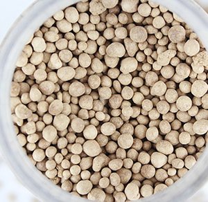


The Ammoniation and Granulation method is a fertilizer production process that involves the reaction of potassium chloride with concentrated sulfuric acid to form potassium bisulfate solution. Phosphoric acid is then added, followed by neutralization with ammonia, producing a slurry containing potassium sulfate, ammonium sulfate, and ammonium phosphate. This slurry is used as the raw material for granulation to form compound fertilizers. During the granulation stage, a series of chemical reactions occur — ammonia reacts with sulfuric acid, potassium bisulfate, and phosphoric acid — resulting in a mixture of ammonium sulfate (NH₄)₂SO₄, potassium sulfate (K₂SO₄), monoammonium phosphate (MAP), and diammonium phosphate (DAP). These compounds combine to form high-nutrient, chlorine-free fertilizers suitable for various crops and soil types. Although this method is not widely used in Japan, it remains popular in China and several European countries due to its low raw material cost, high production efficiency, and stable product quality. In China, for example, ammoniation granulation lines can achieve outputs of 30,000–100,000 tons per year, providing a cost-effective solution for producing potassium sulfate-based NPK compound fertilizers.
What is the Mechanism of the Ammoniation Granulation Method?
Chemical Reactions in the Ammoniation Granulation Process
During the ammoniation granulation process, the following chemical reactions occur among the raw materials:
- KCl + H₂SO₄ → KHSO₄ + HCl
- H₂SO₄ + 2NH₃ → (NH₄)₂SO₄
- 2KHSO₄ + 2NH₃ → K₂SO₄ + (NH₄)₂SO₄
- H₃PO₄ + 2NH₃ → (NH₄)₂HPO₄
- H₃PO₄ + NH₃ → (NH₄)H₂PO₄
The so-called coating-drying granulation process involves spraying the high-concentration slurry generated from these reactions onto seed particles using nozzles. The coated particles are then dried with hot air to form large granules.
Characteristics of the Ammoniation Granulation Method
Low raw material cost
Since this method uses low-cost potassium chloride and crude phosphoric acid as raw materials, ammoniation reactions during granulation simultaneously produce ammonium sulfate, potassium sulfate, and phosphate compounds, reducing overall material cost.
Energy-saving
The ammoniation reaction is exothermic; the heat generated helps evaporate moisture from the slurry, thus lowering the energy required for drying the granules.
High granulation efficiency and quality
Because the reaction products form a high-concentration slurry, using a rotary-type slurry coating and drying granulator ensures high efficiency and good granule quality.
Environmental and safety concerns
Hydrogen chloride (HCl) gas is generated during production, and its recovery cost is relatively high. Additionally, ammonia leakage is a potential risk, posing challenges for environmental protection and safety management.
The Equipment list for the Ammoniation Granulation Process
The ammoniation granulation method produces granules using the slurry generated from chemical reactions; therefore, coating granulation is the most commonly used production technique.
In addition to coating granulation, drum granulation and agitator granulation can also be employed, but considering production efficiency and cost, the coating granulation process offers the best cost-performance ratio. A typical production line for ammoniation reaction and slurry coating granulation mainly consists of a reactor, mixing tank, ammoniation reactor, rotary coating-drying granulator, screening machine, and dust collector.
1. Reactor
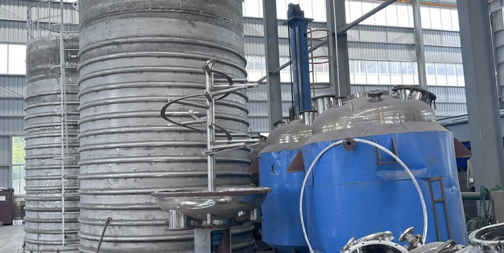
The reactor is a jacketed stainless steel vessel (see Fig. 1). Potassium bisulfate (KHSO₄) solution is produced by the reaction of KCl and H₂SO₄ under steam heating through the jacket. The hydrogen chloride gas generated during the reaction is carried away, absorbed in water, and recovered as hydrochloric acid.
2. Mixing Tank
The mixing tank is used to blend potassium bisulfate and crude phosphoric acid to form the feed slurry.
It is equipped with an agitator, and if necessary, materials such as urea or monoammonium phosphate (MAP) can be added (see Fig. 2).
3. Ammoniation and Neutralization Equipment
The slurry discharged from the mixing tank has high viscosity and low fluidity, so its neutralization reaction with ammonia requires high temperature and pressure conditions. Two types of ammoniation reactors are commonly used:
- Downflow-tube neutralization reactor (DT type)
- Pipe reactor
Downflow-Tube Neutralization Reactor
This reactor consists of a reaction section and a separation chamber. Inside the reaction section, a downflow tube is concentrically installed within the tank. To minimize slurry flow resistance, the cross-sections of the downflow tube, the gap between the tube and tank wall, and the lower circulation passage are all designed to be uniform. The upper separation chamber provides space for gas–liquid separation of the slurry. A baffle plate is installed at the center to suppress slurry upward flow, and an outlet is provided for slurry discharge. A pressure-reducing valve on the top releases steam. (Fig. 3 shows the structure of the DT-type neutralization reactor.)
Reaction process:
Heated slurry is fed into the downflow tube from the side inlet, while ammonia gas is introduced from the bottom. The exothermic neutralization reaction generates steam, creating a gas–liquid mixture that rises due to density difference and ammonia gas flow. After contacting the baffle, the gas and liquid separate part of the slurry is discharged for coating granulation, and the rest circulates back down through the outer gap to the downflow tube for further reaction. Separated steam is vented through the pressure-reducing valve.
Operating conditions:
- Pressure: ≈ 0.3 MPa
- Temperature: >150°C
- Reaction time: <1 minute
This system offers stable control and minimal mechanical failure, making it popular for small and medium-sized fertilizer plants.
Pipe-Type Neutralization Reactor
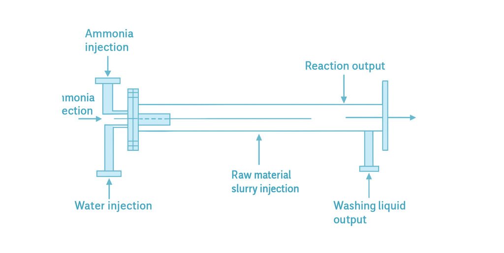
The pipe reactor completes the ammoniation reaction instantly in a unidirectional flow of slurry and ammonia gas within a pipeline. Designs vary depending on raw materials, products, and manufacturer specifications. The most common configuration is the cross-type ammoniation reactor system (see Figs. 4 and 5). The reaction pipe is about 3–6 meters long. Liquid ammonia is injected through one inlet, while the raw material slurry is fed from a 90° cross inlet. The two streams meet and react instantaneously. Due to the exothermic nature of the reaction, the temperature rapidly rises to around 150°C, generating a pressure of 0.2–0.25 MPa, completing the neutralization within about 1 second At the end of the reactor, a nozzle is connected directly to the rotary coating-drying granulator. The reaction pressure drives the slurry product through the nozzle, spraying it into the rotating drum for granulation. This pipe-type ammoniation reactor is highly efficient and suitable for large-scale production, hence widely adopted by major fertilizer manufacturers.
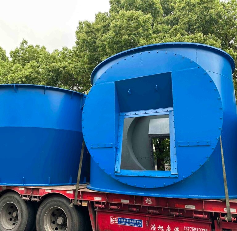
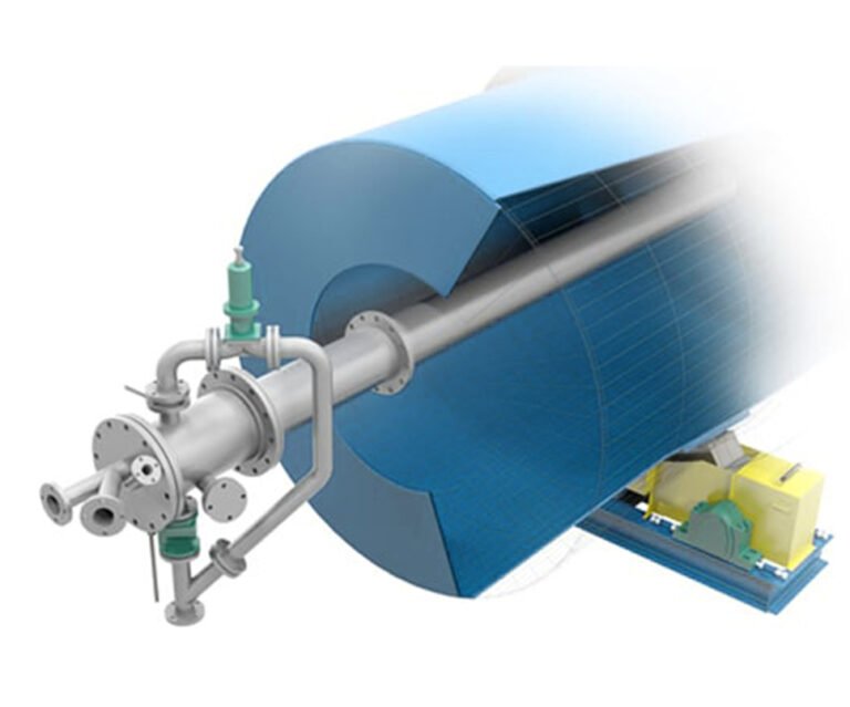
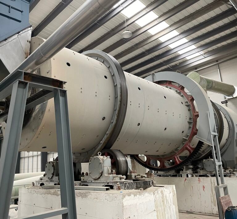
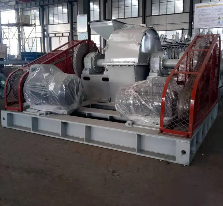
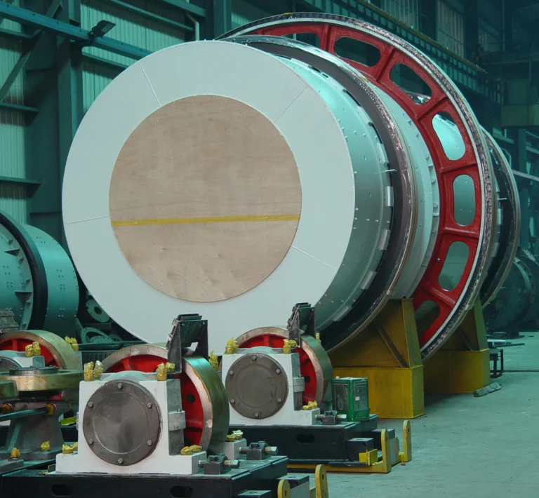
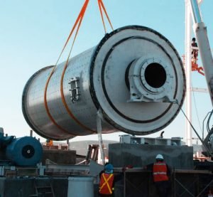
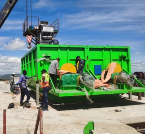
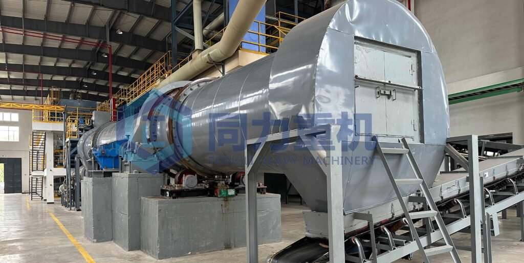
4. Rotary Coating-Drying Granulator
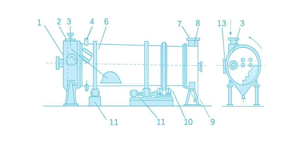
The general structure of the rotary coating-drying granulator is shown in Figure 6.
The drum is installed with a 1–3° horizontal inclination and rotates at a speed of 3–5 rpm.
At the front end of the drum are mounted a slurry spray nozzle, recycled material inlet, and hot air inlet.
In the front section, guide plates are installed to distribute the recycled powder evenly, while in the middle section, L-shaped lifting plates are fitted to lift and drop granules during rotation.
Some designs also include ammonia injection pipes positioned at the bottom or rear of the drum. These allow ammonia gas to be introduced during granulation, enabling the ammoniation reaction and granule formation to occur simultaneously.
At the rear end of the drum, a product hopper is mounted at a 90° angle to the drum axis to discharge finished granules.
A hot air outlet is located above the hopper (see Figure 7).
The structure of the spray nozzle is shown in Figure 8.
Under the pressure of a high-pressure pump and compressed air, the slurry is atomized into a fine mist and sprayed into the drum of the rotary coating-drying granulator.
Working Principle
- The slurry generated from the ammoniation reaction is sprayed horizontally into the rotating drum and becomes atomized upon expansion.
- The fine mist droplets contact and adhere to the surface of existing particles and are then dried by hot air.
- As the drum rotates, particles fall to the lower section, are lifted again by the L-shaped lifters, and repeatedly undergo coating and drying cycles.
- Through this continuous process, particles gradually grow in size.
- When the granules reach the desired size, they move to the rear end of the drum and are discharged through the product outlet at the bottom of the hopper.
Granule Formation and Growth
- Inside the coating-drying granulator, the formation and growth of fertilizer granules proceed as follows:
- The discharged product is first screened.
- Undersized granules are returned directly as recycled feed, acting as seed nuclei.
- Oversized granules are crushed and also recycled as seed material.
- The slurry sprayed from the nozzles coats the recycled seed particles, adhering to their surfaces.
- The coated layer is dried by hot air, and through repeated spraying and drying cycles, the granules gradually enlarge.
- The portion of slurry that does not attach to seed particles is also dried in the drum, forming small particles that can later act as new seed nuclei.
- The atomized slurry can also act as a binder, combining several fine particles into larger granules.
5. Screening System
The granulated product discharged from the rotary coating-drying granulator is transferred by an elevator or belt conveyor to a screening machine for classification.
- Qualified granules (within the desired size range) are sent as final products.
- Oversized granules are crushed and recycled to the front of the drum as seed particles.
- Undersized granules are returned directly without modification.
- A standard vibrating or rotary screen is typically used for this process.
6. Dust Collection System
The exhaust gas from the rotary granulator/dryer contains a significant amount of ammonia gas.
This exhaust is washed with dilute phosphoric acid before being released into the atmosphere.
The washing solution (dilute phosphoric acid containing absorbed ammonia) is returned to the mixing tank and reused as a raw material for the ammoniation reaction, thus improving material efficiency and reducing environmental emissions.
Step by Step Ammoniation Granulation Production Process
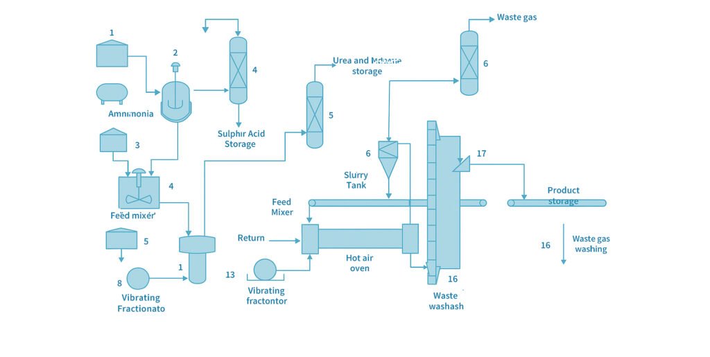
The production process of ammoniation granulation is illustrated in Figure 9. First, potassium chloride (KCl) is fed into the reaction vessel (3), where 98% concentrated sulfuric acid is added. The mixture is stirred and indirectly heated by steam to a temperature of 100–130°C, reacting for 45–60 minutes to form potassium bisulfate (KHSO₄). To ensure complete reaction of potassium chloride, an excess of sulfuric acid is required. Typically, the mixing ratio of KCl to concentrated H₂SO₄ is 100:135–150 (by weight). During the reaction, hydrogen chloride gas (HCl) is produced and sent to the hydrochloric acid absorption tower (4), where it is absorbed in water and recovered as hydrochloric acid. The resulting mixture of potassium bisulfate solution and unreacted sulfuric acid is transferred to the slurry mixing tank (7), where crude phosphoric acid is added as a feed material. The mixing ratio of potassium bisulfate solution to crude phosphoric acid (containing 29% P₂O₅) depends on the target N, P, and K composition of the final product and generally ranges from 100:100–150. Crude phosphoric acid may also be replaced with monoammonium phosphate (MAP). When MAP is used, the mixing ratio of potassium bisulfate solution to 60–70% MAP solution is typically 100:90–130. To increase the nitrogen content of the product, urea (10–15%) may also be added to the mixture. The mixed raw material slurry is then pumped to the neutralization reactor (9), where it reacts with ammonia.
- Potassium bisulfate reacts to produce potassium sulfate (K₂SO₄) and ammonium sulfate ((NH₄)₂SO₄).
- Sulfuric acid forms ammonium sulfate.
- Phosphoric acid forms monoammonium phosphate (MAP) and diammonium phosphate (DAP).
- Urea remains unreacted in the slurry.
The pH of the reacted slurry is adjusted to 5.0–6.0.
If the pH exceeds 6.5, ammonia may be released again during the subsequent granulation and drying stages, so control is required. After neutralization, the reaction slurry is pressurized by a high-pressure pump (10) and sprayed into the rotary coating-drying granulator (12) through nozzles in a fine mist form, coating the fertilizer particles’ surfaces and being dried by hot air. The rotation of the drum lifts and tumbles the particles. As they fall and move toward the discharge end, repeated coating and drying cause the particles to grow gradually in size. Granules reaching the rear end of the drum are discharged through the product outlet into the hopper. When a pipe-type neutralization reactor is used, the pressure generated by the ammoniation reaction is sufficient to spray the slurry directly into the granulator without a high-pressure pump. The granulated product discharged from the coating-drying granulator is conveyed by an elevator (13) or belt conveyor to the screening machine (14).
- Undersized granules remain as they are and are recycled as seed nuclei.
- Oversized granules are crushed once and returned to the front of the granulator as recycled material for nucleation.
Through slurry coating and rotational drying, the resulting granules have a round surface, high compressive strength, and excellent mechanical durability. The presence of ammonium sulfate and ammonium phosphate in the slurry significantly enhances granule formation and strength. The exhaust gas from the coating-drying granulator passes through a cyclone dust collector (18) to remove dust and then enters the exhaust gas scrubbing tower (20), where it is washed with dilute phosphoric acid.
This process absorbs unreacted ammonia and other gases before the clean gas is released into the atmosphere. The phosphoric acid wash solution is then returned to the slurry mixing tank (7) and reused as raw material, improving efficiency and minimizing waste. Finally, the screened product may be dried again if necessary. The dried product is then cooled with cold air to below 40–50°C, and subsequently packaged for sale.
Equipment list for a 100,000 ton per year Ammonia Nitrate NPK Fertilizer Production line
| No. | Equipment Name | Function Description | Main Material / Structure | Typical Specification / Parameters |
| 1 | Potassium Chloride Storage Tank | Stores potassium chloride raw material before feeding to acid reaction system | Carbon steel with anti-corrosion lining | Volume: 20–30 m³; Equipped with level gauge and discharge valve |
| 2 | Sulfuric Acid Tank | Storage of concentrated sulfuric acid used for reaction with KCl | Acid-resistant carbon steel or FRP | Volume: 20 m³; Material: Q235 + Anti-corrosion lining |
| 3 | Reaction Tank | Reacts KCl with H₂SO₄ to form potassium bisulfate solution | Stainless steel or lined carbon steel | Temp: 100–120°C; pH control; Volume: 10 m³ |
| 4 | Hydrochloric Acid Absorption Tower | Absorbs HCl gas generated during acid reaction | FRP packed tower with circulation pump | Height: 6–8 m; Diameter: 1–1.5 m |
| 5 | Urea & MAP Storage Tank | Stores urea and monoammonium phosphate solution for later mixing | Carbon steel or stainless steel | Volume: 15–20 m³; Heating coil optional |
| 6 | Phosphoric Acid Tank | Storage tank for phosphoric acid before mixing | FRP or lined carbon steel | Volume: 20 m³; Acid-proof lining |
| 7 | Slurry Mixing Tank | Mixes phosphoric acid, ammonium, and other solutions into slurry | Stainless steel with agitator | Volume: 10–15 m³; Motor: 11–15 kW |
| 8 | Ammonia Storage Tank | Stores liquid ammonia for neutralization and granulation | Pressure vessel, carbon steel | Capacity: 20–30 m³; Working pressure: 1.6 MPa |
| 9 | Guided Flow Neutralization Reactor | Neutralizes acid slurry with ammonia; main chemical reaction unit | Stainless steel pressure vessel with internal baffle | Temp: 100–120°C; Volume: 10 m³ |
| 10 | High-Pressure Pump | Transfers slurry to granulation drum | Stainless steel centrifugal pump | Flow: 20–40 m³/h; Pressure: 1.5–2.5 MPa |
| 11 | Hot Air Furnace | Supplies hot air to rotary dryer | Coal, gas, or oil-fired | Air temp: 350–500°C; Thermal efficiency >85% |
| 12 | Rotary Coating-Granulation Dryer | Main unit for granulation and drying; completes ammoniation granulation | Carbon steel drum, internal lifting plates | Diameter: 2.2–3.0 m; Length: 14–18 m; Capacity: 10–20 t/h |
| 13 | Bucket Elevator | Lifts dried granules to screening section | Carbon steel, chain or belt type | Capacity: 15–30 t/h; Height: 8–12 m |
| 14 | Rotary Screener | Separates qualified product, oversize, and fines | Carbon steel cylinder screen | Diameter: 1.2–1.8 m; Length: 4–6 m |
| 15 | Recycle Conveyor | Returns oversized and undersized granules to granulation section | Belt conveyor | Width: 500–650 mm; Length: Custom |
| 16 | Product Conveyor | Transports finished granules to product storage | Belt conveyor | Width: 500–650 mm; Length: Custom |
| 17 | Product Storage Tank / Bin | Stores finished NPK granules before packing | Carbon steel hopper or silo | Capacity: 10–20 t |
| 18 | Dust Collector | Collects dust from dryer, screener, and conveyors | Pulse bag filter or cyclone type | Efficiency: ≥99%; Air volume: 10,000–20,000 m³/h |
| 19 | Exhaust Scrubber Tower | Cleans acidic exhaust gases from process system | FRP tower with alkali solution circulation | Height: 6–8 m; Diameter: 1–1.5 m |
| 20 | Waste Gas Scrubber (Secondary) | Secondary stage for exhaust purification | FRP or PVC packed tower | Efficiency: ≥95%; Equipped with demister |
Precautions in the Granulation and Drying Process: the key to success
1. Mixing Ratio of Potassium Chloride and Sulfuric Acid
To completely convert potassium chloride into potassium bisulfate, a slight excess of concentrated sulfuric acid is required. The remaining sulfuric acid from the reaction forms ammonium sulfate in the subsequent ammoniation step, so there is no waste. In addition, during coating granulation, the slurry containing ammonium sulfate helps improve the particle strength after granulation. Therefore, it is recommended to set the molar ratio of potassium chloride to sulfuric acid at 1:1.03–1.05.
2. Addition of Urea
When only potassium chloride, sulfuric acid, crude phosphoric acid, and ammonia are used as raw materials, the granulated fertilizer will have a high phosphorus and potassium content but a low nitrogen content. To increase nitrogen, urea is often added during the pre-ammoniation mixing stage. However, under the high temperature of the granulation process, urea can form biuret nitrogen, which may exceed the allowable limit if too much urea is added. Therefore, the amount of urea should be controlled within 10–15%, and attention must be paid to drying air temperature and drying time during granulation.
3. Spray Nozzle
The atomization condition of the slurry sprayed from the nozzle has a major impact on particle adhesion and drying performance. Usually, an external-mixing twin-fluid nozzle (where the slurry in the inner tube mixes instantly with compressed air in the outer tube) is used. When the spray angle is 30–50°, both the slurry and compressed air pressures are 0.3–0.4 MPa, and the jet velocity is about 200 m/s, the operation is stable. The nozzle position is also crucial. If the nozzle is positioned close to the granules and aimed at the dense zone of lifted particles, the coating rate (ratio of slurry adhering to granules) will be higher, improving both product yield and production efficiency.
4. Moisture Content of the Slurry
The moisture content of the slurry affects atomization, drying efficiency, and productivity.
- When the moisture content is too low, the required spraying pressure increases, making atomization difficult and causing nozzle clogging. The partially dried slurry produces more fines, reducing efficiency.
- When the moisture content is too high, atomization is easier, adhesion is better, and the formed granules have higher strength and better surface gloss. However, more hot air is needed for drying, and insufficient drying may cause product caking.
- Generally, the moisture content should be maintained at 25–35%, and variation should be minimized.
5. Recycle Ratio
Recycled material acts as the seed nucleus for granulation.
- If the recycle rate is too low, the slurry strikes the drum wall instead of the seed particles, causing scaling.
- If the recycle rate is too high, the number of nuclei increases, reducing slurry adhesion per nucleus and slowing particle growth.
- Both extremes lower product yield and increase power and heat consumption, reducing efficiency.
- An appropriate recycle ratio ensures a uniform curtain of seed particles in front of the nozzle so the sprayed slurry adheres properly. Typically, the recycle-to-product ratio is 4–6:1. Maintaining stable recycle flow is also critical.
6. Temperature of Drying Hot Air
The hot air in the dryer flows in the same direction (co-current) as the slurry spray and particle movement. Therefore, higher inlet temperatures improve drying efficiency and reduce heat consumption. However, if the hot air temperature is too high, the slurry may dry before adhering to the granules, lowering the coating rate and increasing fines. In addition, excessive outlet temperature can cause thermal decomposition of ammonium phosphates. Normally, the inlet air temperature is set between 380–450 °C.
7. Product Outlet Temperature
Ammonium phosphate begins thermal decomposition above 180 °C, and when it exceeds 200 °C, ammonia may be released. When urea is used, since its decomposition temperature is about 135 °C, the product temperature at the granulator outlet should be controlled within 80–90 °C. The exhaust hot air temperature should be 100–110 °C.
8. Negative Pressure Inside the Drum
Applying a certain level of negative pressure inside the drum prevents hot air leakage and dust escape, improving the working environment. However, excessive negative pressure allows cold outside air to enter, reducing drying efficiency, worsening granulation conditions, and increasing heat consumption. The negative pressure depends on the suction capacity of the blower connected to the rear air outlet. Generally, it is maintained at 0–100 Pa (0–75 mmHg).
9. Secondary Drying
If the moisture content of screened product exceeds 2%, it may solidify during storage or transport. Therefore, it is necessary to further dry the product with hot air at 100–200 °C, reducing the final moisture to below 1.5%.
Conclusion:
In summary, the ammoniation granulation process has been one of the most widely used compound fertilizer production methods in China since the 1990s. At its peak, more than 40% of NPK compound fertilizer plants adopted this technology because of its simple process flow and stable product performance. The process combines chemical reactions and physical granulation in a single system—ammonia reacts with acids phosphoric and sulfuric acid to form ammonium salts, while the slurry produced is directly granulated to create uniform fertilizer particles. In recent years, with the development of newer technologies such as steam drum granulation and high-tower prilling, the use of ammoniation granulation has gradually declined, especially in large-scale plants seeking higher automation and product uniformity. However, it still holds a strong position in small and medium-sized fertilizer factories due to its flexibility, low energy consumption (around 70–90 kg of standard coal per ton of product), and ability to use various raw materials like MAP, DAP, and potassium salts. Afterall, ammoniation granulation remains a proven and cost-effective technology. It provides valuable experience for optimizing modern fertilizer production, serving as both a practical solution for many plants today and a historical foundation for the continuous innovation of granulation technologies in the fertilizer industry.