


Introduction:
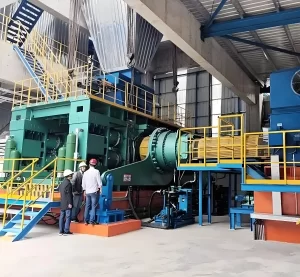
As we all know, cement clinker incineration rotary kiln is heavy industrial machinery, It generally weighs 300t plus including the shell weight and lining inside. So, what kind of drive systme can power a heavy rotary kiln? The answers will be given in the this article. There are many transmission drive method for rotary kilns. In order to meet different industrial needs, Tongli Heavy Machinery has developed a variety of drive types for cement clinker calcination rotary kilns. Tongli girth gear&pinion transmission achieves a transmission efficiency of more than 98% through the conjugate motion of the involute tooth profile, forming a technical monopoly in large cement kilns and metallurgical kilns that withstand 10⁵N・m torque. Tongli friction transmission relies on the friction torque between the contact pairs to transmit power. Its elastic sliding characteristics can buffer 5%-8% of the instantaneous impact load, which is suitable for low-speed and stable operation of small and medium-sized hazardous waste incineration kilns and lime kilns. Hydraulic transmission uses the coordinated control of the volumetric hydraulic pump and the servo motor to achieve stepless speed regulation within the range of 0.1-5r/min. Chain transmission transmits motion through the meshing of chain links and sprockets. Although the polygon effect causes a speed fluctuation of 3%-5%, it is economical under light load conditions and high temperature conditions with a single-stage transmission ratio of ≤6 and a power of ≤100kW. In this article, we will explore each rotary kiln drive type in detail, comparing their working principles, applications, and suitability for various operating conditions.
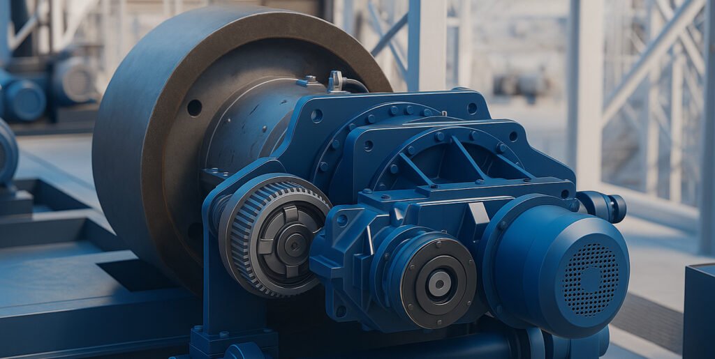
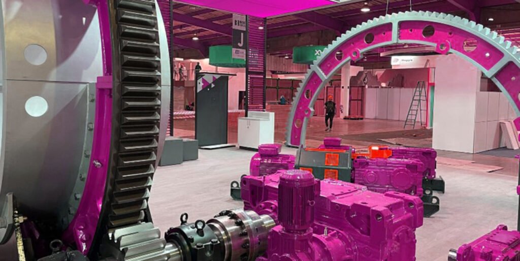
1. Rotary kiln girth gear and pinion drive assembly
1.1 Overall introduction:
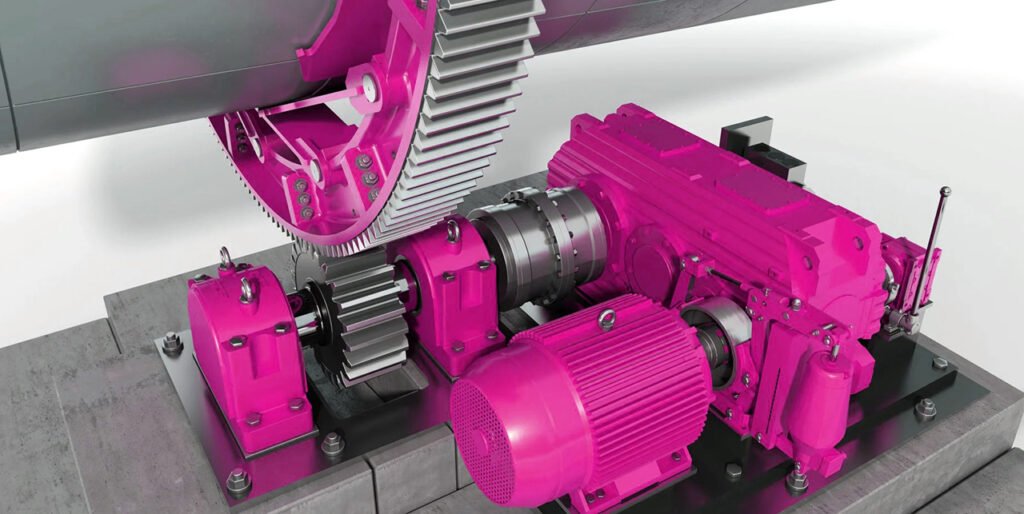
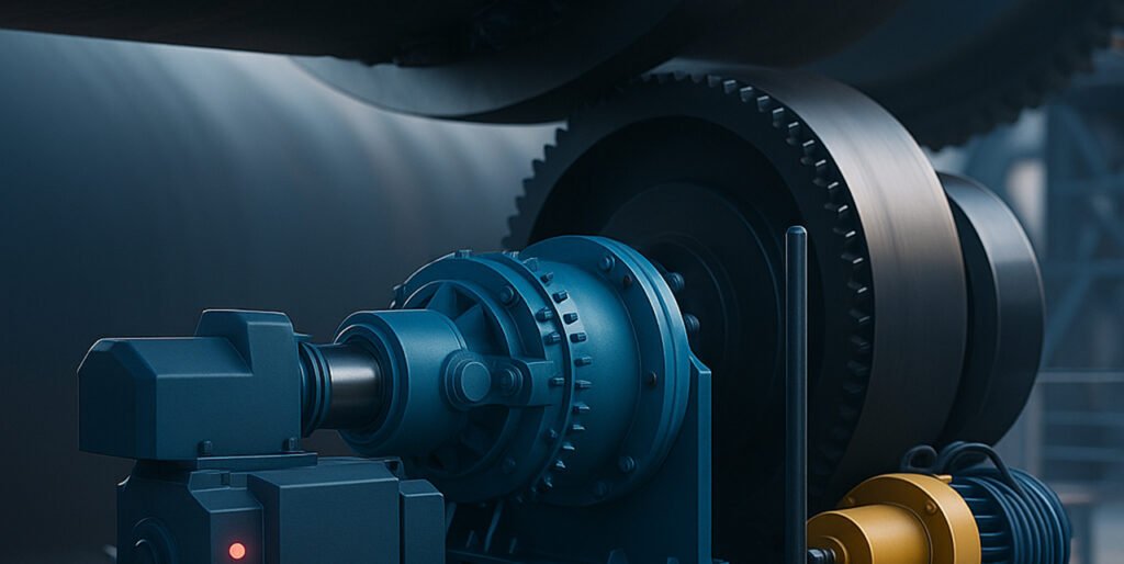
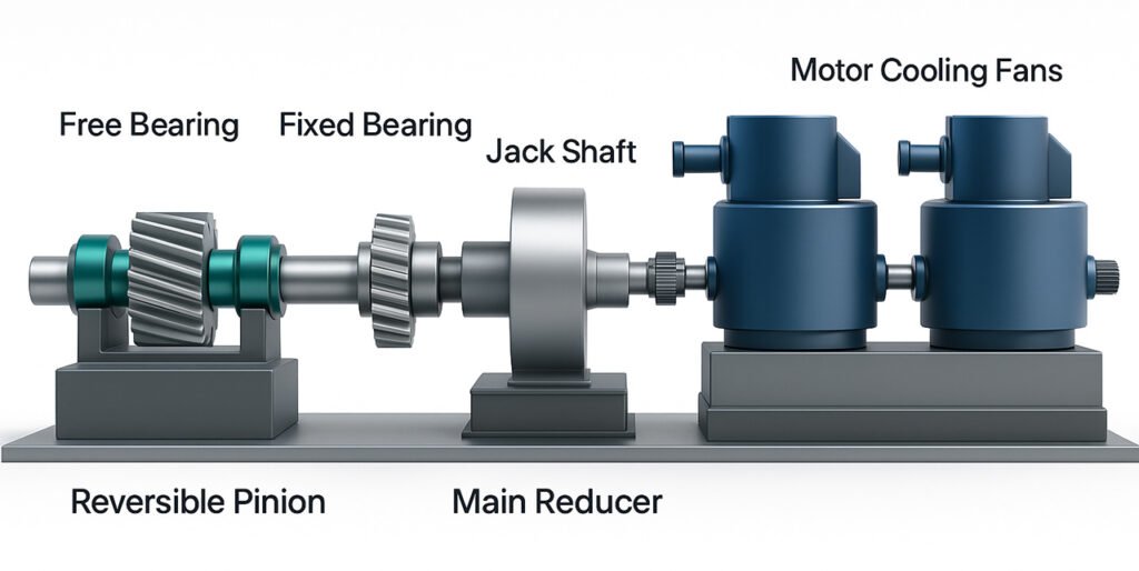
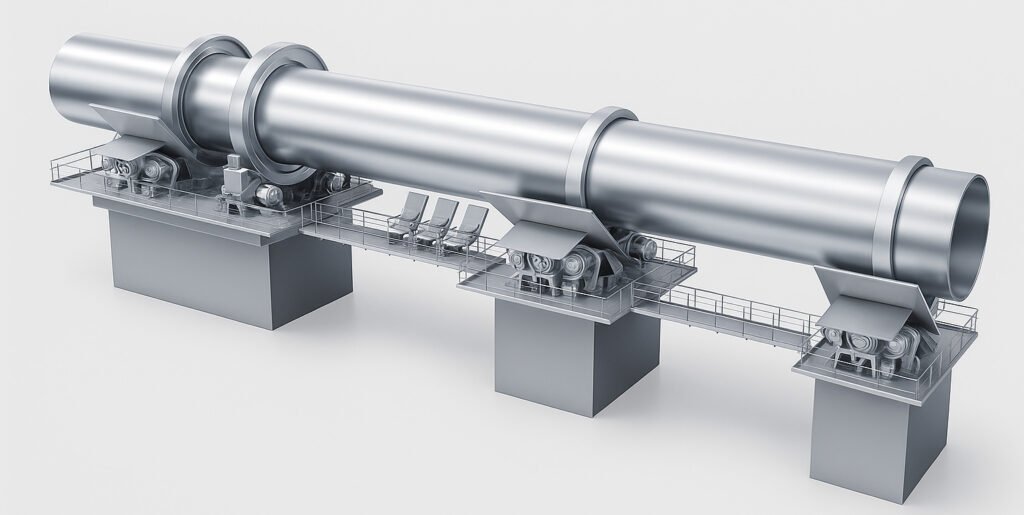
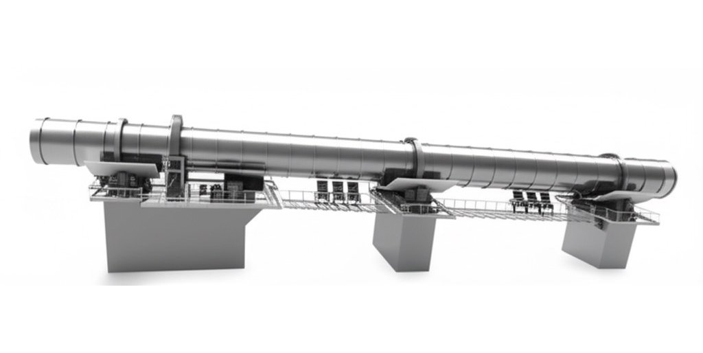
The large girth gear and small gear pinion of the rotary kiln realize the reduction transmission through the tooth surface meshing, converting the high-speed rotation of the motor into the low speed required by the kiln body, meeting the speed requirements of the processes such as calcination and drying of materials in the kiln. The large gear is fixed on the shell of the rotary kiln, and the small gear is fixed on the support bearing. The two transmit power through meshing, and the motor drives the reducer to transmit the power to the small gear meshing with the large gear ring, driving the kiln body to rotate at a speed of 0.5-4 rpm. The large gear ring usually adopts a segmented cast steel structure and is connected to the kiln body through a spring plate to compensate for thermal expansion deformation.
1.2 What are the components of a rotary kiln gear pinion drive system?
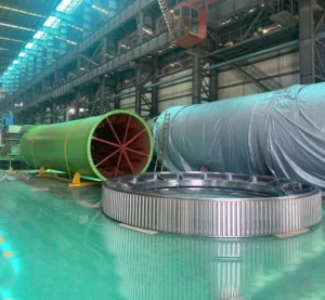
Girth Gear
The rotary kiln gear is an annular transmission component, fixed to the middle or tail of the kiln body by a spring plate or rigid connection, and rotates synchronously with the kiln body. Its diameter is usually 1.2-1.5 times the diameter of the kiln body (e.g. a φ4m kiln body is equipped with a φ4.8-6m gear). The material is mostly ZG42CrMo cast steel. After quenching and tempering, the hardness reaches 220-280HB, the tooth surface contact fatigue strength is ≥600MPa, and it can withstand a super-large torque of 1000-5000kN・m. As a driven part, it meshes with the pinion to achieve reduction transmission. It is the core of power transmission under heavy load conditions. The tooth side clearance (usually 0.2-0.5mm) needs to be regularly checked to ensure the meshing accuracy. Girth gear can be divided into two types based on the structure: by whole or by halves:
One piece by whole rotary kiln girth gear
Integral large gear is an integrated structure. The gear blank is integrally cast, milled, and hobbed. There is no joint gap between the tooth surface and the wheel body. The advantages of this structure are good rigidity, stable transmission, strong load-bearing capacity, and can effectively avoid the vibration and wear problems caused by the splicing error of the half-type gear. However, due to processing and transportation conditions, the size and weight of the integral gear have an upper limit, which is suitable for scenes with high stability requirements.
Half-split rotary girth gear
The half-split gear is a gear that is split into two parts along the axial or radial direction and assembled into a whole structure through bolts, dowel pins and other connectors. Its significant advantage is that it is easy to install, repair and transport. It is especially suitable for large gears with large diameters (usually more than 1 meter) and heavy weights. It can solve the assembly problem of integral gears in a small space. However, the half-split structure will increase the processing accuracy requirements, and it is necessary to ensure the fit of the splicing surface to avoid transmission shock.
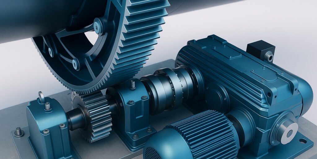
Pinion
The pinion is the active transmission part of the rotary kiln, meshing with the large gear and connected to the motor through the reducer to output power. It is mostly made of 42CrMo forged steel, with a hardness of 300-350HB after surface quenching, a tooth surface roughness of ≤Ra1.6μm, and a modulus of 25-50mm to match the large gear. The speed of the pinion is generally 30-150r/min, the transmission ratio is 10:1-30:1, and the efficiency is 94%-98%. It needs to withstand the reaction force of the large gear, and the single tooth load can reach 50-150kN. The tooth root bending stress needs to be controlled to ≤800MPa during design to avoid the risk of broken teeth. Rotary kiln pinion also has two types which is helical and straight:
Helical teeth rotary kiln pinion
The tooth direction of the helical rotary kiln pinion is inclined at a certain angle of 15°-30° to the axis. Compared with spur teeth, the tooth surface contact is progressive when the helical teeth are meshed, the contact area is larger, the transmission is smoother, the impact and noise are significantly reduced, and it can withstand a larger load. It is suitable for large and high-load rotary kiln equipment (such as cement and metallurgical kilns). However, the helical transmission will generate axial force, which requires a matching thrust bearing for balance, increasing the complexity of the equipment structure; and the processing accuracy requirements are high, and the manufacturing cost is slightly higher than that of spur teeth. The tooth direction error must be strictly controlled during installation to ensure the meshing accuracy and extend the service life.
Straight teeth rotary kiln pinion
The tooth direction of the spur rotary kiln pinion is parallel to the axis, with a simple structure, mature processing technology, low manufacturing cost, and convenient installation and maintenance. It is a common transmission component for small and medium-sized rotary kilns. Its meshing mode is instantaneous line contact, with high transmission efficiency, but the impact is large during the meshing process, the noise is relatively obvious, and the load bearing capacity is weaker than that of helical teeth. It is suitable for scenes with small loads and low requirements for transmission stability. Since there is no axial force, the matching bearing structure is simpler and the failure rate is low. However, spur teeth are prone to tooth surface wear and fatigue pitting under high speed or heavy load, and the tooth surface condition needs to be checked regularly to ensure transmission reliability.
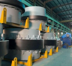
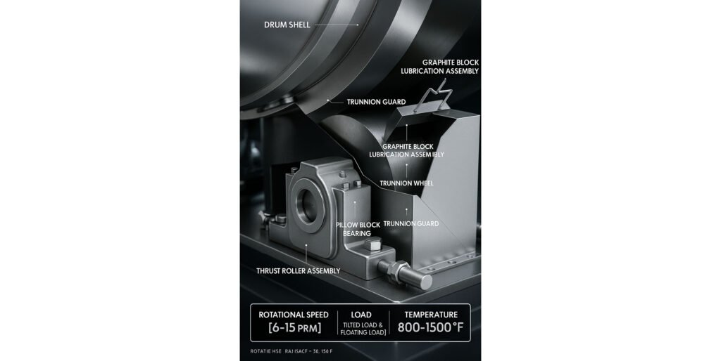
Riding ring
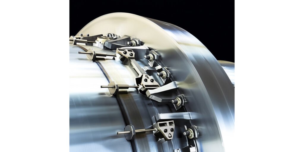
The wheel band or so called riding ring is an annular load-bearing component mounted on the kiln body, which transfers the weight of the kiln body including the material to the supporting wheel. Usually, 2-3 groups are set for each kiln, and the spacing is 10-15 times the diameter of the kiln body. The material is ZG35CrMo, the cross section is mostly rectangular, the thickness is 50-200mm, and the gap with the kiln body is controlled at 0.5‰-1‰ of the kiln body diameter, such as 2-4mm for a φ4m kiln body, to compensate for thermal expansion and contraction. Its contact surface hardness is 240-280HB, the contact stress with the supporting wheel is ≤300MPa, and the load-bearing capacity can reach 1000-3000t/group.
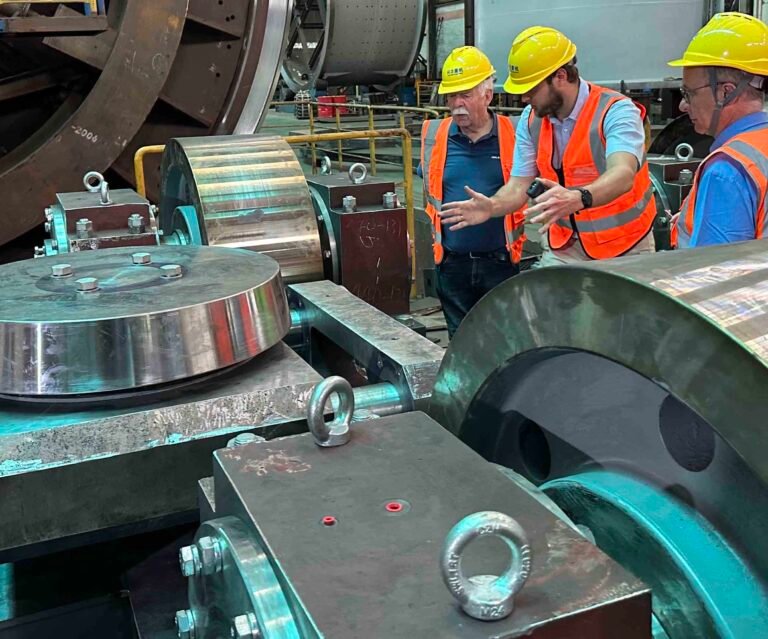
Support roller
The supporting roller is a rolling part that supports the wheel belt and the entire kiln body. It is usually installed in pairs, 2-4 per group, and arranged symmetrically at an inclination angle of 3°-5° to balance the axial force of the kiln body. The material is ZG35CrNiMo, the surface hardening hardness is 38-45HRC, the diameter is 0.3-0.5 times the diameter of the wheel belt, and the length is 50-100mm wider than the wheel belt. The supporting roller bearings are mostly spherical roller bearings with a load capacity of 500-2000kN and a speed of 5-20r/min. Regular lubrication (lubricating oil viscosity 460-680cSt) is required to control the temperature rise ≤40℃.
Thrust roller
The retaining wheel or the official term is thrust roller is used to limit the axial movement of the kiln shell caused by thermal expansion and contraction. It is usually arranged on both sides of the wheel belt, with 1-2 sets per kiln. Its diameter is 0.2-0.3 times the diameter of the wheel belt, and its material is ZG42CrMo, with a surface hardness of 300-350HB, and the contact pressure with the side of the wheel belt is ≤50MPa. The retaining wheel is divided into active and passive types:
the passive retaining wheel is triggered by the movement of the kiln body, and the active retaining wheel is controlled by the hydraulic system to promote the axial displacement of the kiln body (maximum stroke ±50mm), ensuring uniform wear of the contact position between the wheel belt and the supporting roller.
Motor
The driving motor provides power for the rotary kiln and needs to meet the characteristics of low speed and high torque. Asynchronous motors or variable frequency motors are commonly used. The power range is 55-500kW, corresponding to the kiln diameter of 3-6m. The starting torque must reach 1.5-2.5 times the rated value. The speed adjustment range is 0.5-5r/min through the inverter. The working system is S1 continuous operation, the insulation level is F, and the protection level is IP54 to adapt to dusty environments.
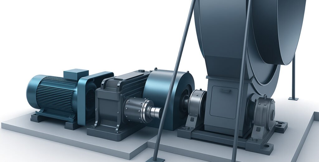
Gearbox/reducer
The reducer or I call gearbox is a reduction device that connects the motor and the pinion. It mostly uses a hardened cylindrical gear reducer with a transmission ratio of 10-50 single-stage or multi-stage combination and an efficiency of 92%-96%. The input speed on the motor side is 1500r/min, the output speed on the pinion side is 30-150r/min, the rated output torque is 50-500kN・m, the box body is made of HT300 cast iron, the gear material is 20CrMnTi carburized and quenched, the hardness is 58-62HRC, and it needs to withstand an impact load with a short-term overload factor of 1.2.
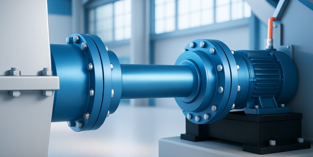
Coupling
Couplings are used to connect motors, reducers, pinions and other components to transmit torque and compensate for installation deviations. Elastic pin couplings or diaphragm couplings are commonly used. Elastic pin couplings are suitable for medium and low torques (≤50kN・m), and can compensate for radial deviations ≤0.1mm and angular deviations ≤1°; diaphragm couplings are suitable for high torques (>50kN・m), with radial deviation compensation capabilities of ≤0.2mm and angular deviations of ≤0.5°. The material is 40Cr (diaphragm thickness 0.3-1mm), the allowable speed is 3000r/min, and it is maintenance-free without lubrication. Notice coupling also has 3 types: mechanical/hydraulic/magnetic:
Mechanical elastic coupling
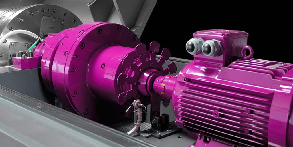
Mechanical elastic coupling is a mechanical component that transmits torque through elastic elements (such as rubber, spring, metal diaphragm, etc.), which can compensate for the relative displacement (axial, radial, angular) between two shafts and buffer vibration. Its elastic elements can absorb impact energy, reduce the dynamic load of the transmission system, and protect the motor and equipment. Common types include rubber elastic coupling (low cost, suitable for medium and low torque), diaphragm coupling (metal elastic parts, high temperature resistance, high precision, used in high-speed occasions), spring coupling (strong load-bearing capacity, suitable for large displacement). It is widely used in general machinery such as water pumps, fans, conveyors, as well as automobiles, machine tools and other fields. It is easy to install and maintain, but the elastic elements have aging problems and need to be replaced regularly.
Hydraulic coupling
Hydraulic coupling is a hydraulic transmission device that uses the kinetic energy of liquid (usually oil) to transmit torque. It consists of a pump wheel, a turbine and a casing. The motor drives the pump wheel to rotate, so that the liquid obtains kinetic energy. The high-speed liquid impacts the turbine to drive the load to rotate. There is no mechanical contact between the two. Its core feature is that it can achieve flexible transmission. When starting, the motor starts without load to reduce the impact current; when overloaded, the pump wheel and the turbine slip to protect the motor and equipment. The output speed can be adjusted by the filling amount (some models), which is suitable for occasions with frequent starts and large load changes, such as mining conveyors, crushers, metallurgical equipment, etc. However, the transmission efficiency is slightly lower than that of mechanical couplings, and the hydraulic system needs to be maintained regularly, and there is a risk of oil leakage.
Magnetic coupler
The magnetic coupler transmits torque based on the principle of magneto-electric induction, and consists of an active rotor (connected to the motor), a driven rotor (connected to the load), and an isolation cover. The permanent magnet of the active rotor generates a magnetic field, and the conductor of the driven rotor cuts the magnetic flux lines to generate eddy currents, forming an electromagnetic force to drive the driven rotor to rotate. The two have no mechanical contact and are physically isolated by the isolation cover. The advantage is that it does not require sealing and is suitable for environments with flammable, explosive, corrosive or high hygiene requirements (such as chemical pumps and food machinery); it can buffer impacts, achieve overload protection, and has smooth transmission and low noise. However, there is a certain slip (usually 3%-5%), the efficiency is slightly lower than that of mechanical transmission, the cost is higher in high-speed and high-torque situations, and the performance of permanent magnets is greatly affected by temperature, so high-temperature environments need to be avoided.
Bearing
The rotary kiln bearing is used to support rotating parts (such as supporting wheels, pinions, and reducer shafts). Supporting wheel bearings are mostly spherical roller bearings (230 series), with a rated dynamic load of 500-2000kN and an allowable axial clearance of 0.1-0.3mm; pinion shaft bearings are commonly tapered roller bearings (30000 series), which bear radial and axial combined loads, with a contact angle of 15°-25°. When the speed is 30-150r/min, the temperature rise is ≤40℃ (ambient temperature 35℃). Ok so once again the bearing of a rotary kiln also has several different types:
Spherical roller bearings
Spherical roller bearings are one of the most widely used bearings in the rotary kiln transmission system. Its structural characteristics are that the inner ring has double raceways, the outer ring raceway is spherical, and the roller is drum-shaped. This design enables it to have a strong self-aligning ability and can compensate for the angular error caused by the installation deviation of the shaft or the shaft deflection. The allowable angular deviation is 1°~2.5°. During the operation of the rotary kiln, the shaft of the transmission part may be slightly bent due to high temperature and heavy load. The spherical roller bearing can avoid the contact between the roller and the edge of the raceway through its own self-aligning function, thereby reducing local stress concentration. At the same time, it can withstand large radial loads and certain axial loads. It is suitable for low-speed, heavy-loaded and axis-deflected working conditions. It is one of the core bearing types that support the rotation of the rotary kiln cylinder.
Thrust spherical roller bearings
Thrust spherical roller bearings are mainly used to bear axial loads and have a certain self-aligning ability. Its structure consists of a thrust washer, a raceway ring, a drum roller and a retainer. The outer ring raceway is spherical. In a rotary kiln, the cylinder will generate an axial downward thrust due to the tilted installation (usually the tilt angle is 3%~5%). The thrust spherical roller bearing can effectively withstand this axial force and compensate for the axis deviation caused by installation or deformation (the allowable angle deviation is about 0.5°~1°). This bearing is usually used in conjunction with a spherical roller bearing. The former bears the main axial load and the latter bears the radial load, jointly ensuring the stable operation of the rotary kiln transmission system. It has a large load-bearing capacity and strong impact resistance. It is suitable for low-speed, heavy-load and significant axial force working conditions, but it has high requirements for lubrication conditions and requires regular maintenance to avoid overheating and wear.
Double-row cylindrical roller bearings
Double-row cylindrical roller bearings consist of an inner ring, an outer ring, double-row cylindrical rollers and a cage. Its raceway is linear, the contact area between the rollers and the raceway is large, and the radial load capacity is extremely strong, but it hardly bears axial loads and has poor self-aligning ability (the allowable angle deviation is extremely small, usually less than 0.1°). In the rotary kiln transmission system, double-row cylindrical roller bearings are often used in parts with high radial stiffness requirements and small axis deflection, such as the connection between the output shaft of the reducer and the pinion. It can disperse radial loads and reduce bearing deformation through the design of double-row rollers. It is suitable for high-speed, heavy-load and high-precision installation scenes. When used with thrust bearings, it can further optimize the force balance.
Bearing housing
The bearing seat is used to fix the bearing and transfer the load. The bearing seat of the supporting wheel is mostly a split cast steel part (ZG270-500) with a load capacity of 1000-3000kN and is connected to the foundation by bolts (preload ≥ 200kN); the pinion bearing seat is an integral cast iron part (HT250), the bearing seat hole and the bearing fit tolerance is H7/js6, the end face runout is ≤0.05mm/m, and a lubrication oil circuit (pressure 0.2-0.4MPa) is required for forced lubrication.
Base frame
The base is a rigid structure that supports reducers, motors, pinions and other components. It is welded with steel or poured with concrete. The flatness error is ≤2mm/m, and the load-bearing capacity is 1.5 times the total weight of the equipment (including dynamic load). The connecting bolts between the base and the foundation need to be pre-buried (M30-M64), with a pre-tightening torque of 500-3000N・m, to ensure that the amplitude is ≤0.1mm (at the pinion) during operation to avoid poor gear meshing due to vibration.
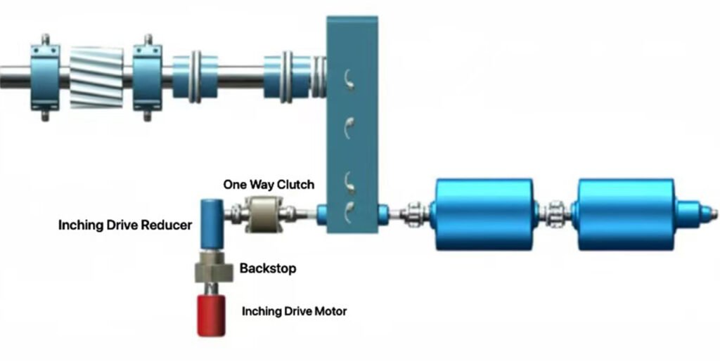
Auxiliary inching drive motor
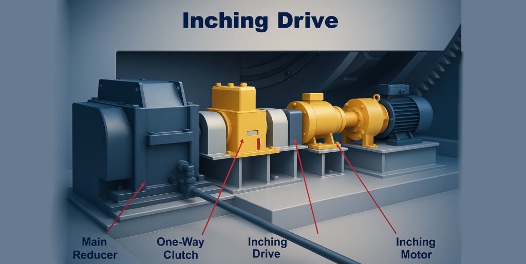
The auxiliary inching drive motor is used to rotate the kiln body at a low speed during kiln maintenance. The power is 5.5-15kW and the speed is 0.1-0.5r/min. It is switched with the main drive system through the clutch. It must have a self-locking function (such as a worm gear reducer) to ensure that the kiln body is fixed at any angle during maintenance. The torque is ≥1.1 times the rated torque of the main motor.
Emergency brake
The emergency brake is used for emergency braking when the kiln body fails suddenly. It is usually a disc brake with a braking torque of 1.5-2 times the rated torque (such as 300-1000kN・m), a response time of ≤0.5s, a brake disc made of 45 steel (surface hardness 200-250HB), and a friction plate made of ceramic material (friction coefficient 0.4-0.5). It can be automatically triggered when the power is off or overspeed (>5r/min), ensuring that the kiln body stops at a distance of ≤1m.
1.3 Kiln Gear Pinion meshing mechanism
The large girth gear and the small pinion gear are meshed through the involute tooth profile. The gear teeth of the active small gear push the gear teeth of the driven large gear, converting the motor power into kiln body rotation torque after deceleration. When meshing, the tooth surface contacts to form a normal force, whose component generates a circumferential force to drive the kiln body to rotate, and the radial component is borne by the bearing system. To ensure stable transmission, the tooth side clearance needs to be controlled at 0.2 to 0.5 mm, and the tooth surface contact spot should not be less than 60% along the tooth length direction and not less than 40% along the tooth height direction. During the meshing process, the tooth surface is usually subjected to a contact stress of ≤1200 MPa and a bending stress of ≤800 MPa. It is necessary to use alloy materials such as 42CrMo for tempering to achieve a hardness of 220 to 350HB and a tooth surface finishing roughness of ≤Ra1.6 microns to reduce wear and fatigue failure and ensure that the transmission efficiency is maintained at 94% to 98%.
Girth gear adopt straight teeth or helical teeth? which is better?
- The advantages of spur straight gear transmission are simple structure, parallel tooth direction and axis, low manufacturing and installation difficulty, and 15%~20% lower cost than helical gear. Its meshing is instantaneous line contact, and the transmission efficiency is slightly higher, up to 98%. However, spur gear has a small contact area at the moment of meshing, concentrated impact load, and is prone to vibration and noise. Especially under high speed or high torque conditions, the tooth surface wear rate is 20%~30% faster than helical gear, and the load-bearing capacity is limited. It is only suitable for small kilns with a diameter of less than 3 meters and a torque of less than 500 kN·m.
- Helical gear transmission is arranged with a helical angle (usually 8°~15°) and a progressive surface contact process. The contact area is 40%~60% larger than that of spur gear, and the load-bearing capacity is significantly improved. It can adapt to large kilns with a diameter of more than 4 meters and a torque of more than 1000 kN·m. Its transmission is stable, the vibration amplitude can be controlled within 0.05 mm, and the noise is reduced by 10~15 decibels. However, helical teeth will generate axial force, which requires a matching thrust bearing for balance. In addition, the helix angle accuracy must be guaranteed during manufacturing (error ≤±0.5°), and the installation and alignment requirements are higher, which increases the cost relatively.
1.4 Gear Pinion drive transmission method: single drive or twin drive?
Here is our recommandation: single drive is suitable for the light load requirements of small and medium-sized kilns with low cost and simple structure, while double drive meets the heavy load requirements of large kilns with dispersed load and high load-bearing capacity. The actual selection needs to be comprehensively judged based on the kiln specifications, production capacity and operating costs.
Single drive of rotary kiln
Single drive refers to the transmission form that realizes power transmission through the meshing of a set of small gears and large gears. It is the mainstream choice for small and medium-sized rotary kilns. Its core structure is: a driving small gear (connected to the output shaft of the reducer) is single-point meshed with the large gear fixed on the kiln body, and the kiln body is driven to rotate through the power chain of motor-reducer-small gear. Applicable scenarios are mainly used for working conditions with kiln body diameter ≤4 meters, total weight ≤1000 tons, and rated torque ≤1500kN・m. It is commonly used in small cement kilns (daily output ≤2000 tons), lime kilns or metallurgical roasting kilns.
Specifications of single drive of rotary kiln
- Small gears are mostly made of 42CrMo forged steel (hardness 300-350HB), large gears are made of ZG42CrMo cast steel (hardness 220-280HB), modulus 25-40mm;
- Transmission efficiency 94%-98%, transmission ratio 10-25, small gear speed 30-100r/min;
- During installation, the tooth side clearance is controlled at 0.2-0.5mm, and the contact spot along the tooth length is ≥60% and the tooth height is ≥40%.
Feartures of single drive of rotary kiln
- Advantages: simple structure, few parts (only 1 set of gear pairs), low initial cost (20%-30% lower than double transmission), easy maintenance (single-point lubrication, inspection);
- Limitations: large gears are subjected to concentrated force (meshing point is single-point load), and long-term operation is prone to increased local tooth surface wear (single-side wear is 15%-20% higher than double transmission), and due to the torque limitation of single gears, it cannot be adapted to large and heavy-loaded kilns.
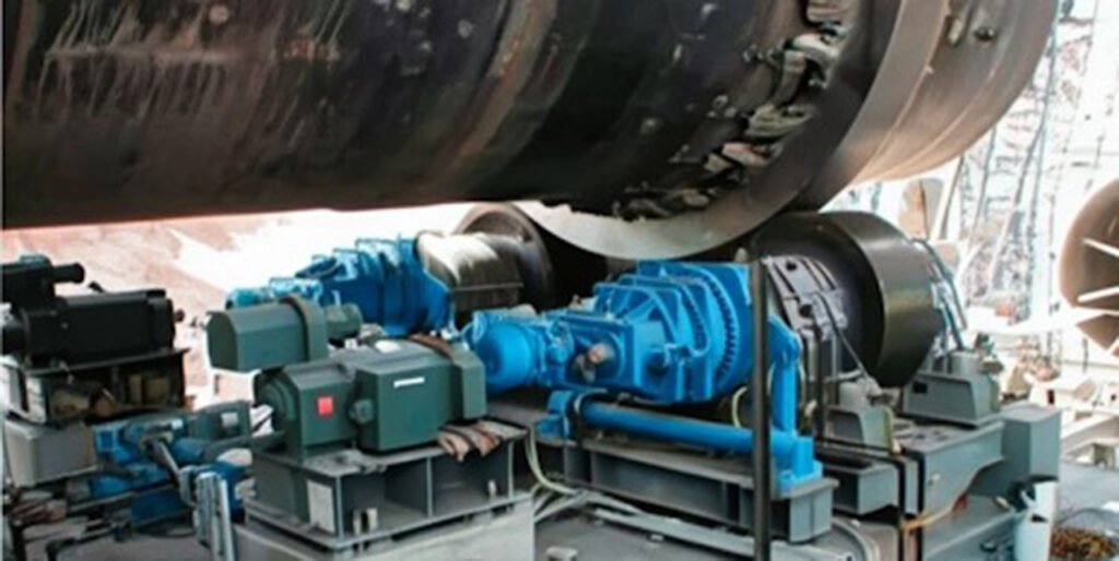
Twin drive of rotary kiln
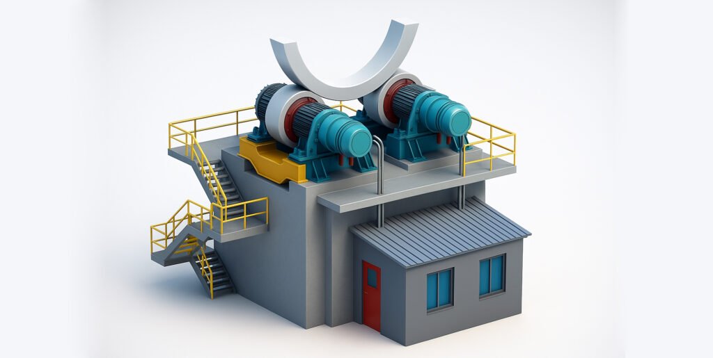
Dual drive is a form of transmission of power through two sets of symmetrically arranged pinions meshing with the same large gear, which is suitable for large heavy-load rotary kilns. Its structure is: two pinions are connected to the reducer respectively, symmetrically distributed on both sides of the large gear (angle 180°), and two-point meshing is achieved through synchronous control to jointly drive the large gear and kiln body to rotate. Applicable scenarios are mainly used for working conditions with kiln body diameter > 4 meters, total weight > 1000 tons, and rated torque > 1500kN・m, such as large cement kilns (daily output ≥ 3000 tons), alumina roasting kilns, etc.
Technical parameters of twin drive rotary kiln
- The parameters of the two sets of pinions are exactly the same (material, module, tooth shape are the same), and the meshing points with the large gear are symmetrically distributed (angle error ≤0.5°);
- The total transmission efficiency is 92%-96% (slightly lower than single transmission, because there is a small energy loss in the synchronization of double gears), and the torque borne by a single set of pinions is 45%-55% of the total torque;
- The diameter of the large gear can reach 5-8 meters, the module is 40-60mm, and the overall load capacity is 2000-3000kN・m;
- It is necessary to be equipped with a synchronous control system (such as electronic gear synchronization or mechanical linkage mechanism) to ensure that the speed difference between the two sets of pinions is ≤0.5r/min to avoid meshing interference.
Feartures of twin drive rotary kiln
- Advantages: The force on the large gear is dispersed (the double-point meshing reduces the contact stress of the tooth surface by 30%-40%, from 1200-1500MPa of single transmission to 800-1000MPa), and the wear is more uniform (the service life is extended by 20%-30% compared with single transmission); the load can be shared by two motors, reducing the power requirements of a single reducer and motor (the power of a single motor is 160-315kW, and the total power is 320-630kW), and it can adapt to heavy-load conditions;
- Limitations: The structure is complex (two sets of small gears, dual reducers and synchronous systems are required), and the initial cost is 40%-60% higher than that of a single transmission; the installation accuracy requirements are higher (the meshing clearance difference between the two sets of small gears and the large gear is ≤0.1mm), and the maintenance workload is large (the lubrication and wear status of the two sets of gears need to be detected synchronously).
1.5 Rotary Kiln gear pinion assembly lubrication oil station
The lubricating oil station for the meshing part of the large and small gears of the rotary kiln is a special hydraulic device that provides continuous lubrication, cooling and impurity filtration for the gear transmission system. It is a key auxiliary system to ensure the reliability of gear meshing. Its core function is to pressurize the lubricating oil through the oil pump and accurately transport it to the meshing area of the large gear and the small gear through the pipeline to form an oil film to reduce the friction and wear of the tooth surface, and at the same time take away the heat generated by the meshing (the tooth surface temperature can usually be controlled below 60℃).
What are the components of a rotary kiln gear pinion lubrication station?
The system usually consists of an oil tank, a gear pump or a plunger pump (working pressure 2.5-4MPa), a filter (precision 10-20 microns), a cooler (inlet and outlet temperature difference ≤15℃), a pressure sensor and a control system. The lubricating oil generally uses extreme pressure industrial gear oil (viscosity grade 320 or 460), which must meet the stability requirements under high temperature (the ambient temperature near the kiln body can reach 80-120℃) and dust conditions. Also the lubrication station usually has specialized manufacturer, so the mechnical rotaru kiln manufacturer source it from them.
How does it work?
During operation, the system adjusts the oil supply in real time through pressure feedback (usually 1.5-3L/min for each pair of meshing teeth). When the pressure is lower than the set value (such as 1.5MPa), it automatically alarms to ensure that the meshing area is always in a good lubrication state. This can extend the life of the gear by more than 30%, while reducing transmission resistance and maintaining transmission efficiency stable at around 95%.
1.6 Rotary Kiln gear pinion assembly How to install? In steps
- Before installation, the foundation review must be completed to check the flatness (≤0.1mm/m), elevation error (≤±0.5mm) and spacing size of the large gear base frame and the small gear reducer foundation, and eliminate the foundation settlement deviation by grinding or gasket adjustment. At the same time, check the accuracy of the parts. The large gear needs to be tested for radial runout (≤0.15mm/m) and end face runout (≤0.2mm/m), the small gear tooth surface roughness must be ≤Ra1.6μm, and the cumulative pitch deviation must be controlled within ±0.05mm. Ensure that the material and heat treatment meet the design (large gear ZG42CrMo hardness 220-280HB, small gear 42CrMo hardness 300-350HB).
- When installing the large gear, first dock the two halves of the split gear at the preset position of the kiln body, adjust the level of the kiln body through the supporting wheels at both ends of the kiln body (≤0.5mm/m), and then tighten the docking bolts to control the misalignment of the joint to ≤0.1mm. Then use a dial indicator to measure multiple points along the circumference to ensure that the large gear is concentric with the kiln body (radial deviation ≤0.2mm).
- The installation of the small gear needs to be based on the large gear. The axis parallelism control is achieved by adjusting the reducer base gasket (deviation within 1m length ≤0.1mm), and the center distance error must be ≤±0.1mm. The color coating method is used to check the meshing contact. After rotating the small gear, the contact spot on the large gear tooth surface is ≥60% along the tooth length direction and ≥40% along the tooth height direction, and the contact area should be located in the middle of the tooth width, and the deviation from both ends should not exceed 10%. The tooth side clearance is determined by the module. When the module is 30-50mm, it is controlled at 0.3-0.6mm. The feeler gauge is used to measure at 6 points evenly distributed on the circumference to ensure that the clearance difference is ≤0.1mm.
- All connecting bolts must be tightened according to the designed torque. Hydraulic tensioners are used to apply pre-tightening force (about 3000-4000N・m) to bolts M30 and above to prevent loosening. After installation, a test run is carried out. First, manually turn the wheel to confirm that there is no jamming, and then run at a low speed of 1-2r/min for 2 hours. Monitor the tooth surface temperature (≤60℃), vibration value (≤0.15mm/s) and noise (≤85dB). After stopping, check the meshing parameters again. If necessary, fine-tune the gasket to correct the deviation until all indicators are stable after 4 hours of continuous operation.
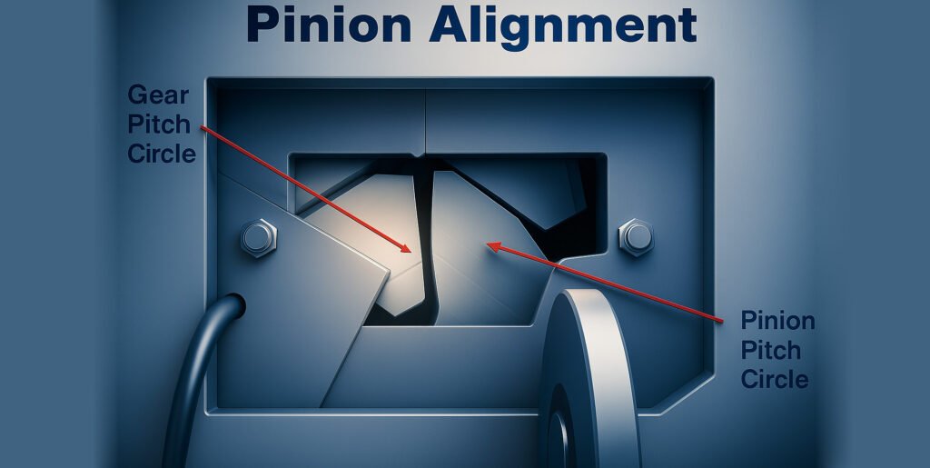
1.7 Precision Alignment of Girth Gears and Pinions
Preliminary preparations
First, make preliminary preparations. The kiln body needs to be fixed in a horizontal support state to ensure that the large gear has no axial movement and radial shaking; clean the oil, scale and impurities on the gear tooth surface and the installation reference surface to expose the metal body to ensure measurement accuracy; prepare high-precision measurement tools, including 0.01mm level dial indicator, laser centering instrument (measurement error ≤0.02mm/m), feeler gauge (range 0-10mm, accuracy 0.01mm) and magnetic table seat.
Determine the reference and positioning
Secondly, determine the reference and positioning. The large gear is used as the reference part because it is rigidly fixed to the kiln body through the hub, and its position stability is better than that of the small gear. Use the dial indicator to detect the radial runout (allowable value ≤0.15mm/m) and axial end face runout (allowable value ≤0.1mm/m) of the large gear. If it exceeds the tolerance, adjust the kiln body support or the large gear fixing bolts first to ensure the stability of the reference.
Implement radial centering
The third step is to implement radial centering. Adjust the center distance between the pinion and the gear to make the tooth side clearance meet the design requirements - the clearance value is usually determined by the module, which is 0.3-0.5mm for a module of 20-30mm and 0.5-0.8mm for a module of 30-40mm. When measuring, select 4 equally divided points (one every 90°) on the circumference of the gear, insert a feeler gauge into the tooth side, record the clearance value of each point, and adjust the horizontal bolts of the pinion base to make the difference between the maximum clearance and the minimum clearance ≤0.1mm to ensure uniform clearance in the circumferential direction.
Complete the axial alignment
The fourth step is to complete the axial alignment. Ensure that the axes of the gear and the pinion are parallel to avoid axial deflection that causes the tooth surface contact to deviate to one end. Set up laser transmitters at the bearing seats at both ends of the pinion, set up receivers at the corresponding positions of the gear, measure the parallelism deviation of the two axes, and require the deflection to be ≤0.1mm per meter length. At the same time, use a dial indicator to measure the axial clearance difference at both ends of the tooth width. If the clearance difference between the input and output ends exceeds 0.15mm, adjust the thickness of the pinion axial gasket (every adjustment of 0.1mm gasket can correct 0.05mm/m deflection) to calibrate until the deviation is within the allowable range.
Verify the contact state of the tooth surface
The fifth step is to verify the contact state of the tooth surface. Use the color coating method to check: evenly apply red lead oil (thickness ≤0.05mm) on the pinion tooth surface, manually rotate the gear 1-2 circles and observe the contact marks on the large gear tooth surface. Qualified contact spots should cover more than 60% along the tooth length direction and more than 40% along the tooth height direction, and the center area should have dense contact and no obvious indentation on the edge. If the spot is biased towards the tooth top, the center distance needs to be reduced; if it is biased towards the tooth root, the center distance needs to be increased; if it is biased towards one end of the tooth width, the axial parallelism needs to be recalibrated, and the adjustment is repeated until it meets the requirements.
Tighten and re-inspect
Finally, tighten and re-inspect. After the adjustment is completed, tighten the pinion base and bearing seat bolts according to the specified torque (usually 80%-90% of the rated torque of the bolts), measure the radial clearance, axial deflection and contact spots again, and confirm that there is no parameter drift caused by tightening. Run the test for 30 minutes without load, use a vibration meter to detect the vibration intensity of the pinion bearing (≤0.1mm/s), and use an infrared thermometer to monitor the tooth surface temperature (≤65℃). If there is no abnormal noise or parameter fluctuation, it is qualified.
1.8 Maintenance tips: Common Failures and Troubleshooting
Girth gear and pionion drive may have some chance to affect the operation overall, so here we listed some common failures and how to solve it and trouble shoot during operation:
Tooth surface excessive wear
- Reason: Insufficient lubrication or lubricant failure (such as carbonization of grease at high temperature), poor contact of tooth surface (eccentric load causes local stress concentration), material dust intrusion between teeth causing abrasive wear.
- Solution: Use high-temperature extreme pressure lubricant (such as synthetic grease containing molybdenum disulfide), establish a lubrication inspection system every 8 hours; recalibrate gear alignment (ensure that the contact spot along the tooth length is ≥60%); install dust cover and regularly clean the debris between teeth. When the wear is serious, the tooth surface needs to be repaired by surfacing welding (using low-hydrogen type welding rod, and 250℃ tempering after welding to eliminate stress).
Tooth root fracture
- Reason: Casting defects (such as shrinkage holes and slag inclusions) in gear material, frequent overload (starting torque exceeds 3 times the rated value), and small tooth root fillet radius leads to stress concentration (design value should be ≥0.15 times the modulus).
- Solution: Ultrasonic flaw detection on new gears (flaw detection level ≥ GB/T 7233.1 level 3); replace the drive system with hydraulic coupling (limit the maximum torque to 2.5 times the rated value); profile welding on the broken tooth part, grind the tooth root fillet to the design standard, and replace the whole tooth if necessary (the material is ZG42CrMo and tempered).
Abnormal noise in gear meshing
- Reasons: Too large (more than 0.8mm) or too small (less than 0.1mm) tooth side clearance, burrs or hard spots on the tooth surface (not finely ground), the pinion shaft and the reducer output shaft are not coaxial (coaxiality error > 0.1mm/m).
- Solution: Adjust the position of the pinion to control the tooth side clearance to 0.2-0.5mm (corresponding to the module 25-40mm); use a fine grinding wheel to grind the tooth surface burrs, and perform local annealing heat treatment on the hard spots (heat to 650℃ and keep warm for 2 hours); calibrate the transmission shaft system with a laser alignment instrument to ensure that the coaxiality error is ≤0.05mm/m.
Radial runout of large gear exceeds the standard
- Reason: loose bolts connecting large gear and kiln body (insufficient preload), fatigue deformation of spring plate (elastic coefficient drops by more than 20%), bending of kiln body causes large gear axis to deviate.
- Solution: Re-tighten the connecting bolts according to the specified torque (M30 bolt preload ≥800N・m), and tighten symmetrically three times with a torque wrench; replace the fatigue deformed spring plate (material is 60Si2Mn, hardness 38-42HRC); measure the straightness of the kiln body (allowable deviation ≤L/1000, L is the length of the kiln body), and correct it by adjusting the height of the support wheel (every adjustment of 0.1mm support wheel height can correct 0.05mm/m of straightness error).
Pinion bearing overheating
- Reasons: Too small bearing clearance (the gland is too tight during installation), too much grease filling (exceeding 60% of the bearing cavity volume), too loose fit between the bearing inner ring and the shaft (fit tolerance is lower than H7/k6).
- Solution: Re-adjust the bearing clearance (the clearance of the spherical roller bearing should be controlled at 0.15-0.3mm); after cleaning the old grease, fill 40%-50% of the bearing cavity volume with high-temperature grease (dropping point ≥200℃); chrome-plated the journal (plating thickness 0.05-0.1mm), ensuring that the fit tolerance reaches H7/k6.
Gear tooth surface bonding
- Reason: Tooth surface oil film rupture under high speed and heavy load (instantaneous temperature exceeds 150℃), insufficient lubricant viscosity (kinematic viscosity is less than 320cSt at 40℃).
- Solution: Replace high-viscosity extreme pressure gear oil (viscosity ≥460cSt at 40℃), and add sulfur-phosphorus additives (content 3%-5%) to the oil; reduce the starting acceleration (extend the starting time from 10 seconds to 30 seconds through the inverter) to avoid instantaneous overload; grind the bonding part to remove the molten metal layer.
Abnormal axial movement of the large gear
- Reasons: failure of the stopper wheel (passive stopper wheel stuck), inconsistent tilt angle of the support wheel (difference in tilt angle on both sides>0.1°), thermal expansion of the kiln body exceeds the design value (when the working temperature is 300°C higher than the normal temperature, the expansion must be ≥0.012mm/℃・m).
- Solution: dismantle the stopper wheel to clean the oil stains, replace the worn friction plate (friction coefficient is kept at 0.4-0.5); re-measure and adjust the inclination of the support wheel (deviation is controlled within ±0.05°); calculate the thermal expansion of the kiln body, adjust the stopper wheel stroke (reserve ±50mm compensation), and ensure that the axial displacement of the large gear is ≤3mm/h.
Gear transmission efficiency decreases
- Reasons: Tooth surface roughness exceeds the standard (Ra>3.2μm), gear centering deviation (parallelism error>0.1mm/m), and bearing lubrication is poor (friction coefficient between rolling element and raceway>0.0015).
- Solution: Fine grinding of tooth surface (reaching Ra1.6μm); calibrating parallelism of gear axis with laser interferometer (error ≤0.05mm/m); using oil mist lubrication system (oil mist particle diameter 2-5μm) to improve bearing lubrication efficiency and restore transmission efficiency to more than 94%.
Pinion shaft bending
- Reason: The output shaft of the reducer is not concentric with the pinion shaft (radial deviation>0.2mm), and the radial force generated when the gears are meshed is too large (exceeding 80% of the rated dynamic load of the bearing).
- Solution: Correct the coaxiality by adjusting the reducer base gasket (each piece is 0.05mm thick); replace the bearing with a higher load capacity (such as replacing the 23030 spherical roller bearing with 23034, and the rated dynamic load is increased from 900kN to 1200kN); straighten the bent shaft (using thermal straightening, heating temperature 250-300℃, and the runout after straightening is ≤0.05mm/m).
Tooth surface contact spot deviation
- Reason: The axis of the large gear and the small gear are not parallel (axial deflection>0.1mm/m), and the height position deviation of the small gear (the error with the center distance of the large gear>0.3mm).
- Solution: Adjust the transverse gasket of the pinion bearing seat (every adjustment of 0.1mm can correct the deflection of 0.05mm/m); measure and correct the center distance (by increasing or decreasing the longitudinal gasket of the gear base, the error is controlled within ±0.1mm); use the coloring method to repeatedly check until the contact spot is located in the middle of the tooth surface (centered along the tooth width direction, the deviation is ≤10% of the tooth width).
Gear connection bolt fracture
- Reason: Insufficient strength of the bolt material (not reaching grade 8.8), uneven preload (torque difference between adjacent bolts>10%), vibration causes bolt loosening (amplitude>0.1mm).
- Solution: Replace 8.8 grade high-strength bolts (tensile strength ≥800MPa); use a torque multiplier to tighten in diagonal order to ensure that the preload deviation is ≤5%; install anti-loosening gaskets (such as toothed locking gaskets) on the bolt head, and apply thread glue (temperature resistance grade ≥200℃) on the thread.
1.9 Adventages of incinetation rotary kiln gear pinion drive
The gear pinion drive method has the following adventages:
- High transmission efficiency, can still maintain more than 90% mechanical efficiency under high temperature conditions of the incineration rotary kiln, reduce energy loss, and meet the needs of continuous and stable operation.
- The transmission torque is large. Through the reasonable design of gear modulus and tooth width, it can meet the torque output of more than 1000kN・m for single transmission system and more than 2000kN・m for dual transmission system, and is suitable for large kiln operation.
- Good running stability. After precision tooth profile processing (tooth surface accuracy reaches level 6 of GB/T 10095.1) and meshing parameter optimization, the impact load coefficient during transmission can be controlled within 1.2, reducing vibration and noise.
- Strong structural rigidity, the gear is integrally cast (material ZG35CrMo) and tempered (hardness 220-260HB), which can withstand the instantaneous overload caused by material fluctuations during the incineration process (short-term overload coefficient 1.5).
- The speed regulation range is wide. With the frequency conversion motor and reducer, it can achieve stepless speed regulation of 0.5-5r/min, meeting the kiln speed adjustment requirements under different material incineration conditions.
- High maintenance convenience, the gear meshing part is easy to observe, and the operating status can be monitored daily through the tooth surface contact spots (along the tooth length ≥60%) and temperature (≤ ambient temperature + 40℃), which is convenient for early fault diagnosis.
- Adapting to high temperature environment, using high temperature grease (dropping point ≥200℃) and heat dissipation structure design, it can work stably for a long time at an ambient temperature of 80-120℃ near the kiln body.
- The transmission ratio is precise. The fixed gear ratio (usually 10-20:1) ensures the stability of the kiln body speed, avoids uneven material residence time caused by speed fluctuations, and improves the incineration efficiency.
- The load distribution is uniform. The load difference between the left and right gearboxes in the dual transmission structure can be controlled within 5%, reducing the eccentric load wear of the single-side gear and extending the service life (design life ≥10 years).
- Strong compatibility, seamless switching with auxiliary drive systems (such as slow drive machines), and safe kiln turning (speed 0.1-0.2r/min) when the main drive fails.
- Large modification space, by replacing the gear pair or increasing the number of transmission stages, it can adapt to the modification needs of kiln expansion (diameter increase of 0.5-1m) or capacity increase (processing capacity increase of 10%-20%), without the need to replace the entire drive system.
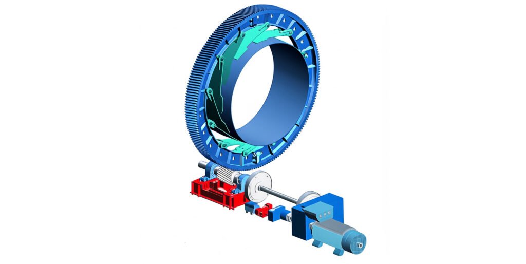
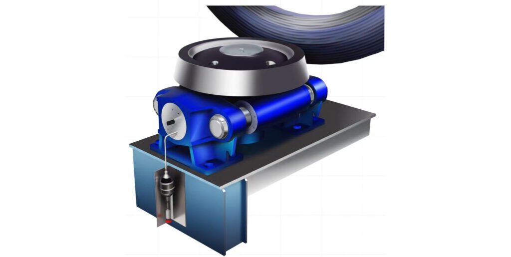
2. Rotary incineration kiln friction drive assembly
We have wrote an article with very detailed introduction of friction drive incinetation rotary kiln, if you are interest in this topic please check our previous article: "A Friction Drive Transmission Incineration Rotary Kiln For Hazardous Waste & Cement Clinker & Limestone"
What Is a Friction Drive in Rotary Kilns?
Friction transmission is a driving method of rotary kiln, which transmits torque through friction to rotate the kiln body. Usually, the friction wheel (active part) contacts the kiln body roller (driven part), and the motor drives the friction wheel to rotate, using the friction between the contact surfaces to drive the roller and the kiln body to operate. It does not require gear meshing and has a relatively simple structure. It is suitable for small and medium-sized kilns or low-torque conditions, such as some experimental rotary kilns. The friction coefficient is a key parameter and usually needs to be maintained between 0.3-0.5 to ensure effective force transmission.
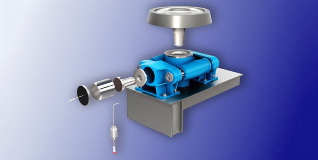
How Friction Drives Work: Key Parts and Function
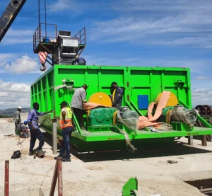
The core components include driving riding ring wheel, motorized support roller, pressure device and driving motor. The motor drives the riding ring to rotate. The friction force is converted into driving torque, which drives the roller and kiln body to rotate. The roller is mostly made of cast steel as ZG35SiMn and the surface of the riding ring is also made of steel casting to withstand the pressure.
Why Use a Friction Drive? Pros and Cons
Advantages: simple structure, easy installation and maintenance, low initial cost; no rigid meshing, can buffer impact and protect the motor. Disadvantages: limited transmission torque (usually ≤500kN・m), low efficiency (about 75%-85%); easily affected by working conditions, high temperature or oil pollution will reduce the friction coefficient and cause slipping. Suitable for small kilns with low load and intermittent operation, not suitable for large industrial kilns.
Wear, Slippage & How to Control Them
Wear mainly comes from the hard contact between the friction wheel and the roller, especially when dust or foreign matter invades. Slip is mostly caused by insufficient friction, such as insufficient pressure, surface oil or high temperature (>150℃ will significantly reduce the friction coefficient). Control measures: Clean the contact surface regularly and keep it clean; maintain appropriate pressure (usually 0.5-1MPa) through a pressurizing device; use wear-resistant materials (such as polyurethane friction wheels), monitor the surface temperature, and cool it down in time.
Application Scenarios: Best Use Cases
Applicable to small and medium-sized, low-torque rotary kilns, such as hazardous waste incineration or clinker material calcining kilns and small environmental protection treatment kilns (processing capacity <500t/h). It is more common in intermittent production in industries such as ceramics and building materials, especially suitable for working conditions that require frequent start and stop or mild impact. It is not suitable for heavy loads (torque >1000kN・m) or continuous high-load operation scenarios such as large cement kilns and metallurgical kilns, because it is prone to slippage and insufficient efficiency.
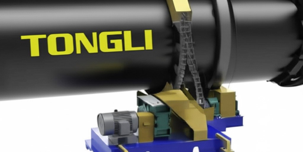
3. Cement kiln chain sprocket transmission drive assembly
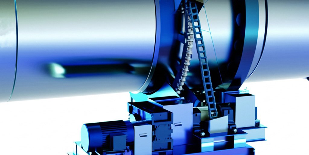
What Is a Chain & Sprocket Drive in Cement Kilns?
The chain and sprocket drive (Chain & Sprocket Drive) of cement rotary kiln is an indirect friction type mechanical transmission form, which is sutable for rotary kiln systems with diameter less than 4m, small production capacity, and low speed rotation. This system is based on the sprocket (sprocket) and chain (industrial chain). The motor and the output shaft of the reducer drive the active sprocket to rotate, and then the chain pulls the driven sprocket to realize the rotation of the rotary kiln cylinder. The sprocket diameter is generally φ300~600mm, and it is often used with 16B or 20B double-row transmission chains.
Chain Sprocket vs. Girth Gear Drive: Which Is Better for Your Kiln?
Chain sprockets are more suitable for small rotary kilns with low speed, low load and compact structure. For large cement clinker or lime kilns, large ring gear and pinion transmission is still the mainstream choice due to its higher load-bearing capacity and transmission efficiency. The design life of the large ring gear system can reach more than 15 years, with stable operation and high precision, but the manufacturing and installation costs are high; in contrast, the initial investment of the chain drive system is only 30% to 50%, which is suitable for projects that are sensitive to budget and do not require high precision.
| Item | Chain & Sprocket Drive | Girth Gear & Pinion Drive |
| Transmission Accuracy | Medium to Low | High |
| Applicable Kiln Diameter | < φ1.8 m | φ1.8 m ~ φ6.0 m |
| Torque Capacity | ≤ 10,000 Nm | Up to 100,000 Nm or more |
| Service Life | Chain: approx. 1–2 years | Girth gear: 10–15 years |
| Installation & Maintenance | Simple, easy on-site assembly | High precision, requires skilled assembly |
| Cost | Around 30%–50% of girth gear system | Higher initial investment |
What are the key components and working principle?
The system mainly consists of a driving sprocket, an industrial chain, a driven sprocket, a support frame and a tensioning device. The driving sprocket is connected to the output shaft of the reducer and drives the chain to run. The chain then pulls the driven sprocket to rotate, thereby driving the rotary kiln cylinder to rotate. The sprocket is usually made of high-strength alloy steel, and the surface is tempered and quenched to improve wear resistance. The chain needs to be an industrial heavy-duty double-row chain, such as 16B-2 or 20B-2.
When Is a Chain Drive the Right Choice?
Chain sprocket drive is particularly suitable for rotary kiln systems with limited space, light torque load and small equipment diameter. In scenarios such as small organic fertilizer drying kilns, sludge incineration kilns, laboratory kilns or small-volume activated carbon kilns, it not only has a simple structure and a short installation and commissioning cycle, but also can significantly reduce initial investment and spare parts costs. Especially in rural or local organic fertilizer processing plants, the chain system has become one of the common choices due to its maintenance-free design and easy operation advantages. If the daily processing capacity is less than 50 tons and the daily operation time of the equipment is less than 16 hours, the chain system is a very suitable choice.
Common Failures and How to Prevent Them
Chain transmission may suffer from chain wear, tooth skipping, sprocket eccentric wear, lubrication failure and other problems in long-term operation, especially in high temperature and high dust environment, which is more likely to intensify wear. The fatigue life of the chain is usually between 8,000 and 12,000 hours, while that of the sprocket can reach more than 20,000 hours. To prevent failure, the chain tension and wear should be checked regularly to keep the chain and sprocket meshing well; the lubrication system should use special oil for high temperature chains to ensure sufficient lubrication and reduce operating noise and heat.
4. Rotary kiln hydraulic transmission drive assembly
What Is a Hydraulic Drive System in Rotary Kilns?
The hydraulic drive system is a transmission method that uses hydraulic oil as an energy transfer medium and provides torque through a hydraulic motor to drive the rotary kiln cylinder to rotate. It is different from the traditional motor-reducer-gear rigid transmission. The hydraulic system has higher flexibility and torque output capacity, and is especially suitable for heavy load, low speed, and high starting load conditions. It is often used in large cement rotary kilns, lime kilns, or hazardous waste incineration kilns. The hydraulic drive can achieve 0 speed start, continuous speed regulation, and even maintain stable operation when the load changes suddenly. The system torque output can reach 40,000~200,000 Nm, and the kiln body diameter is usually above 2.5 meters.
Main Components and Working Principle:
A typical rotary kiln hydraulic drive device is composed of a hydraulic power pack, a variable hydraulic motor, a drive roller, a torque arm/support, a cooling system, and a control unit. Its working principle is: after the hydraulic pump pressurizes the hydraulic oil, it is transmitted to the hydraulic motor through the control valve system, so that the motor outputs a low-speed and high-torque rotational force; the motor is in direct contact with the drive wheel or support wheel on the kiln body, and the kiln body is driven to rotate by friction. The whole process realizes stepless speed regulation and start-stop without impact, and closed-loop torque feedback control can be realized at the same time. The hydraulic oil pressure in the system is usually in the range of 160~250 bar, and the drive speed accuracy can be controlled within ±0.1 rpm.
Advantages of Hydraulic Transmission in Kiln Operations
The hydraulic drive system has many advantages over the traditional motor + gear transmission, especially in rotary kiln systems with heavy loads, high-frequency start-stop or high-precision speed regulation. First, the hydraulic system has extremely high starting torque, and can start smoothly even when fully loaded or stuck, effectively preventing deformation of the barrel or damage to the main shaft; secondly, it has automatic overload protection and soft start capabilities, which can significantly reduce mechanical shock and transmission loss; in addition, the hydraulic system has a fast speed regulation response, which is suitable for special process requirements that require frequent start-stop or low-speed reversal. Compared with traditional transmission, hydraulic drive can reduce starting current by more than 70%, significantly reducing energy consumption and control system pressure. Its service life exceeds 10 years, and maintenance is mainly concentrated on hydraulic oil replacement and cooling system maintenance.
When to Use Hydraulic Drives (Industrial Applications)
Hydraulic transmission systems are usually used in high-load and high-demand scenarios, especially in rotary kiln equipment with extremely high requirements for starting torque, speed regulation accuracy and operating stability. Typical applications include:
- Large cement clinker calcining rotary kiln (φ4.0m and above), which requires continuous 24-hour operation, requires high torque starting and flexible speed regulation;
- Hazardous waste incineration kiln, which requires frequent start and stop, large load fluctuations, and hydraulic system can effectively control thermal shock and torque shock;
- Lime shaft kiln/rotary kiln linkage system, hydraulic drive can realize multi-point synchronous drive and remote centralized control;
- Automated kiln system in intelligent factory, hydraulic system can be directly connected to PLC/DCS system to realize closed-loop control, remote fault diagnosis and other functions.
5. Rotary kiln direct drive
This type is transmission is very rare, as a manufacturer we have only seen a few customer that choose this type of rotary kiln, mainly becasue the kiln is too long, if the torque is too big, will casue the kiln to bend like a cinnamon stick.
The structure and working principle of the direct drive system
The rotary kiln direct drive system consists of an integrated motor + reducer + bearing seat + coupling structure. The motor is a hollow shaft synchronous motor (Torque Motor) or a servo-controlled permanent magnet motor, which is connected to the cylinder or the supporting wheel shaft through a flange, and the power acts directly on the carrier. In order to achieve high torque output, the system will integrate a planetary reducer or a harmonic reduction mechanism. The output speed is between 0.3~1.0 rpm, and the torque range can cover 10,000~300,000 Nm. The entire system has a compact structure, short axial length, and does not require an external lubrication system (some high-performance drive belts have built-in cooling). The operating efficiency is 8%~12% higher than that of traditional mechanical systems.
Advantages of direct drive: high efficiency and low maintenance
Compared with traditional transmission methods, the biggest advantage of direct drive is that the transmission chain is short, the efficiency is high, and the maintenance cost is low. Since the gear pair or chain is eliminated, there is no meshing wear and lubrication problem, and the equipment operation stability is significantly improved. Secondly, the direct drive system can achieve extremely high starting torque, and has high dynamic response capability and stepless speed regulation function, which is particularly suitable for intelligent control system integration. At the same time, it avoids the reverse impact problem caused by tooth gap in traditional drive, and the kiln body runs more smoothly, which is especially valuable for high-end ceramic calcination, lithium battery materials or experimental rotary kilns. In addition, due to the high system integration, the overall equipment noise is low, which is suitable for environmental protection and smart factory requirements.
6. Frequently asked question about rotary kiln drive system(FAQ)
Unlike chain and sprocket drives, which rely on a flexible chain engaging with toothed sprockets (and are prone to wear, stretch, or misalignment under extreme loads), gear drives use rigid, interlocking toothed gears. In heavy-duty setups, a large gear is often mounted directly around the drum’s circumference, meshing with a smaller driven gear. This direct contact ensures precise power transfer, minimal energy loss, and better durability in high-torque, continuous-operation scenarios
In short the need for one drive type over another is dependent on how much power is needed. The selection of gear, friction or chain drive for rotary kiln needs to be accurately matched with working condition parameters:
Gear drive is suitable for large kilns with diameter > 4m and total weight > 1000t. Its transmission ratio accuracy is ±0.5%, efficiency is 94%-98%, and 42CrMo gear (hardness 280-320HB) can withstand torque > 1500kN・m, suitable for heavy-load abrasive scenes such as cement;
Friction drive is suitable for small and medium-sized kilns with diameter ≤3m and total weight ≤500t. It transmits power through contact between friction wheel and kiln body, with friction coefficient of 0.3-0.4, contact pressure of 1.5-2.5MPa, and efficiency of 85%-90%, but it is necessary to avoid slipping caused by adhesive materials;
Chain drive is only used for light load (total weight < 300t) and low speed (≤2r/min) scenes, with transmission ratio error of 5%-8%, efficiency of 85%-90%, but the chain is easily affected by dust wear and has a shorter life than gears. 30%-50%, only recommended for temporary or simple working conditions.
The drive assembly is the component responsible for rotating the kiln. A range of drive assembly configurations are available, including chain and sprocket drives, gear drives, friction drives, and direct drive assemblies.
A chain and sprocket drive for rotary kilns operates through a mechanical setup where a large sprocket is mounted around the rotary drum’s circumference, engaged by a heavy-duty roller chain. This chain connects to a smaller sprocket, which is driven by a gearbox (reducer) linked to an electric motor. When the motor spins, it transfers power through the gearbox to the small sprocket, which pulls the chain, causing the large drum-mounted sprocket—and thus the kiln itself—to rotate. This drive type is specifically designed for small rotary kilns, with a maximum power capacity of up to 50 kW. Beyond this threshold, chain and sprocket systems become impractical: the chain struggles to handle increased torque without stretching or skipping teeth, leading to inefficient power transfer, efficiency drops from 85–90% at 50 kW to below 80% at higher loads and frequent failures. For example, in a 50 kW limestone processing kiln, a chain and sprocket drive may last 1,500–2,000 hours between maintenance cycles, but in a 60 kW kiln, the same setup would require chain replacements every 500–800 hours due to accelerated wear. This makes them unsuitable for larger kilns needing more than 50 kW.
Friction drive assemblies are designed for small-scale rotary kiln applications with low power requirements, typically ranging from 5~50 kW. They are most commonly used with drums that have a diameter of 3 meters or less, making them ideal for compact industrial processes like small-batch calcination or minor material drying operations. In terms of operation, friction drives leverage the contact between rotating components to transfer power. Specifically, two out of the kiln’s four trunnion wheels which support the drum are connected by a single shared shaft. This shaft is linked to a shaft-mounted reducer, which is in turn powered by an electric motor. When the motor activates, it drives the reducer, which rotates the connected shaft and trunnion wheels. The friction between the trunnion wheels and the drum’s surface then causes the drum to rotate. This design eliminates the need for direct toothed engagement unlike gear drives but limits power capacity—for example, a 3-meter diameter drum using a friction drive can reliably handle up to 50 kW, but performance degrades significantly with larger drums due to reduced friction efficiency and increased risk of slippage.
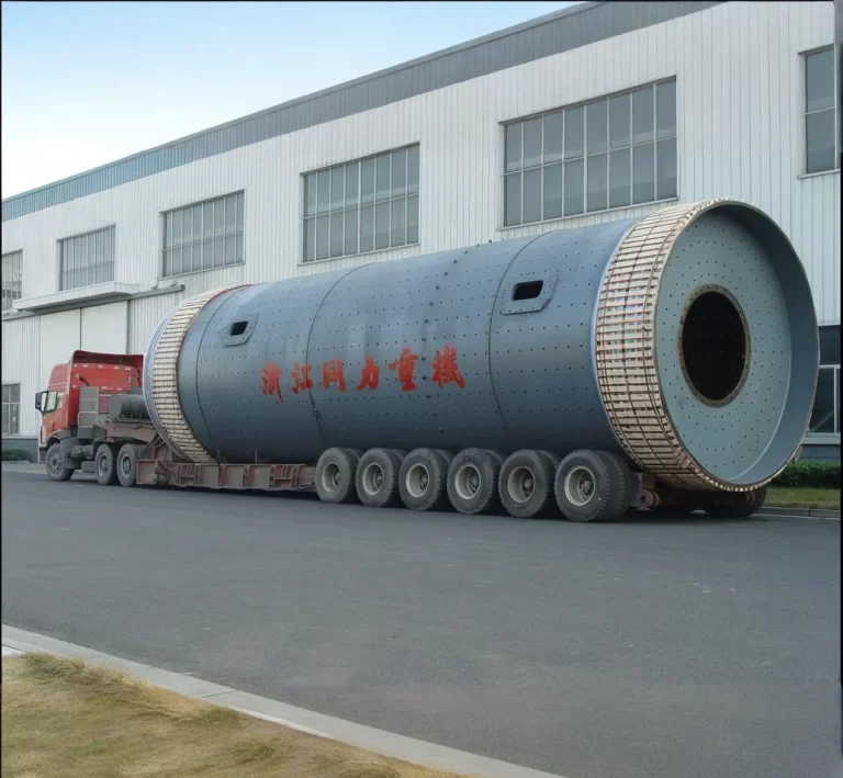
Direct drive assemblies are for small to medium-sized drums especially like ball mill due to their streamlined design, where a shaft mounted on the drum’s solid discharge end plate connects directly to a motor and reducer via couplings or shaft mounts. By eliminating intermediate components like belts or chains, they minimize energy loss typically 1-2% vs. 5-10% for belt drives and reduce space requirements, making them ideal for small kilns or portable mixing drums. This direct connection also enhances operational reliability, as fewer moving parts mean lower risk of breakdowns—key for continuous processes like material drying, where unplanned downtime is costly. However, the rigid connection demands precise alignment often requiring laser tools during installation to prevent premature bearing wear, and they lack the shock absorption of belt drives—making them less suitable for drums handling uneven or abrasive materials that could cause jams.
A girth gear & pinion drive is a large ring gear (girth gear) around the kiln’s shell, meshing with a driven pinion gear attached to a gearbox and motor. It’s designed for heavy-duty applications, offering high torque capacity and durability. By distributing loads over many teeth, it ensures smoother rotation and less wear. However, installation requires precision alignment, and component replacement (especially pinions) can be costly. Regular inspection and proper lubrication are critical to prevent uneven wear and prolong gear life
Friction drives consist of two steel casting support roller connected via a drive shaft powered by a motor and gearbox. Typically employed on cement clinker kilns up to 3 m in diameter or hazardous incineration rotary kiln up to 4m with low horsepower, they’re simpler than gear systems, eliminating the need for large girth gears and pinions. This makes them cost-effective and low-maintenance. Their main drawback is vulnerability to slippage under heavy loads or wet conditions, so they require clean surfaces and periodic tension adjustment to maintain proper traction
A large sprocket mounted to the kiln shell and a smaller sprocket on the motor-reducer, connected by a rolling chain. Suited for small kilns or dryer up to 75 horsepower, they mimic bicycle drivetrain mechanics. Advantages include low cost, ease of maintenance, and quick replacement, and especially it can isolate the heat from the drum to the transmission device making it suitable for high temperature processing. However, chains require frequent tensioning, lubrication, and replacement, and they're not suitable for high-power or heavy-duty kilns due to limited torque capacity
In direct drive systems, a motor and reducer are coupled directly to the kiln’s shaft (often near the discharge end), bypassing external gears or chains. Best for small to medium kilns (≤75 hp), they offer high efficiency, compact layout, and minimal maintenance. Their design reduces mechanical losses and total component count. However, they’re limited in torque and scalability, and retrofitting existing kilns can be complex due to alignment and mechanical integration requirements
Selecting a drive depends on kiln size, horsepower requirements, operating conditions, and maintenance resources.
Chain & sprocket: Small kilns (<75 hp), low torque needs, cost-sensitive.
Friction: Small, low-power kilns; clean dry conditions.
Direct/shaft drive: Medium kilns with ≤75 hp, space or simplicity constraints.
Girth gear & pinion: Large industrial kilns (>75 hp), heavy loads, continuous operation.
Each type balances initial cost, performance, maintenance frequency, and application suitability
Maintenance focuses on alignment checks, backlash adjustment, lubrication, and wear monitoring. Misalignment causes uneven load distribution, leading to tooth damage, noise, or vibration. Pinions tend to wear asymmetrically and should be flipped when possible to balance wear. Regular inspections—preferably during shutdown—help detect gear fatigue or cracking, minimizing downtime and costly replacements
Friction drive slippage is becasue of inadequate support roller-to-shell contact, contamination (dust, moisture, grease), or inappropriate tire hardness. These reduce frictional grip. To minimize slippage, maintain clean contact surfaces, use the correct tire material, monitor pressure, and ensure proper shaft/motor reducer alignment. Inconsistent rotation speed can impair kiln efficiency and product quality
Yes, but recommanded, when using hydraulic drives on driven rollers (instead of gear inhalation), they are good in high torque scenarios, offering smooth start-up and overload protection. Hydraulic systems benefit from precise control and exceptional torque capacity. However, they require hydraulic power packs, hoses, fluid maintenance, and leak prevention systems. They’re ideal where avoiding gear grinding or achieving gentle startup is a priority
Frequent issues include chain stretch or breakage, sprocket wear, misalignment, and inadequate lubrication. Over time, chains elongate under tension, leading to backlash and reduced efficiency. Sprockets wear unevenly, causing poor fit and accelerated wear. Mitigation requires periodic chain tensioning, lubrication, alignment checks, and timely replacement—especially in harsh environments with heat or dust
Auxiliary (jogging) drives—such as small electric motors or diesel units—are very important for preventing kiln “dead spots” during shutdown. They rotate the kiln slowly to avoid thermal distortion and preserve refractory integrity. This is especially critical for girth gear systems. Auxiliary drives activate automatically if main drive power fails or during planned stops, extending component and lining lifespan while avoiding costly repairs.
Conclusion:
So we understand this is a long long article, but congradulations! You've made it here! Cheers! Choosing the right rotary kiln drive type—whether it’s the robust girth gear and pinion, the smooth friction drive, the precise hydraulic system, or the durable chain sprocket transmission—is more than just a mechanical decision; it’s a strategic investment in your plant’s efficiency, reliability, and long-term performance. Whether you're upgrading an existing rotary kiln or designing a new one, understanding these drive types helps ensure optimal torque delivery, minimal maintenance, and peak energy efficiency. For plant managers and engineers, the right drive isn’t just a component—it’s the heartbeat of kiln performance. We Tonli as a manufacturer has 65+ years of experience in rotary kiln manufacturing, from the earlist shaft kiln to the modern rotary kiln, we have the experience and expertise to help you in your business. Now , If you want to know more about the friction drive rotary kiln we have an article here, just click the link below:
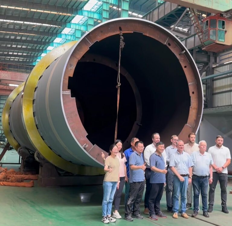
Rotary Kiln Incineration Plant Manufacturer Factory Visit by European Customer
Hazardous Medical Waste Incineration Rotary Kiln Introduction and Factory Acceptance Test(FAT)