


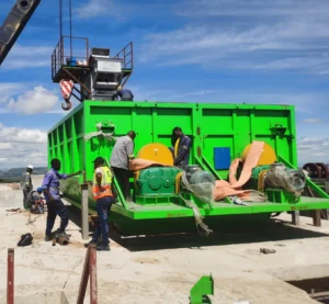


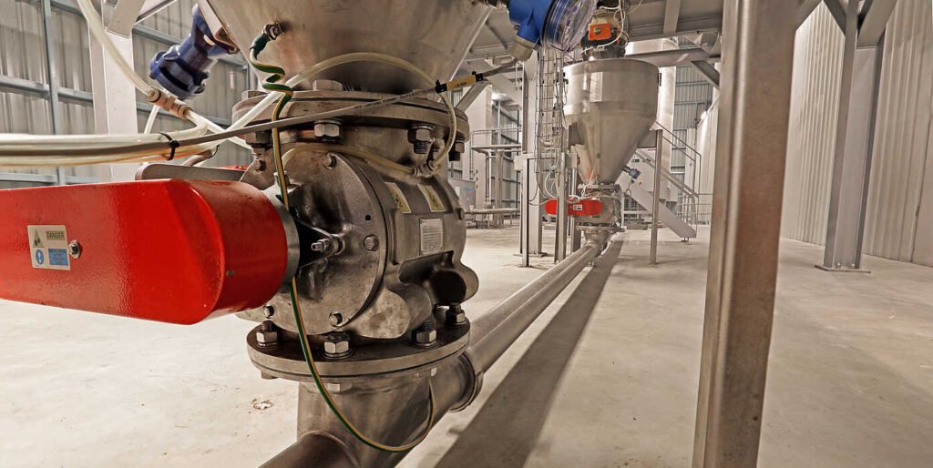
Pneumatic conveying, a technology that uses gas energy to continuously transport powdered and granular materials through closed pipelines, has been developed since the mid-19th century and has become an indispensable material conveying method in modern industrial production. Compared with traditional mechanical conveying, pneumatic conveying offers significant advantages, including a closed system, flexible layout, high degree of automation, and low environmental pollution. Rotary valves are key components of pneumatic conveying systems. Their performance directly impacts the overall conveying efficiency and reliability of the system. Rotary valves primarily serve the dual functions of feed control and airlock sealing in pneumatic conveying systems. They precisely control the flow of material from the silo into the conveying pipeline, while preventing conveying gas leaks and maintaining stable system pressure . Rotary valves are essential equipment in industrial applications and are widely used in industries such as cement, food processing, and chemicals. This article explores the important role of rotary valves in pneumatic conveying and outlines their essential key characteristics.
What is a pneumatic conveying rotary valve
Rotary valves, also known as rotary airlocks, are used to handle a variety of bulk solid materials, from powders to granules. They are typically used when there is a need to separate two areas of differing conditions (most often pressure) while simultaneously transferring solids from one state to another. Therefore, rotary valves (often also called star valves) are used at the beginning and end of pneumatic conveying systems. They transfer solids from a low-pressure area at the beginning of a pipeline to a lower-pressure area, while also helping to separate solids from the airflow at the end of the pipeline. Their robust design enables them to handle varying material properties, such as abrasiveness or cohesiveness, making them a versatile choice for a variety of pneumatic conveying systems. Rotary valves have two primary functions: providing a seal to maintain a proper airlock within the system and allowing material to enter the conveying line from the hopper. A vertical roller mill rotary airlock design typically consists of a rotating element with grooves or vanes that pick up material at the inlet and release it at the outlet, thereby metering the flow of bulk solids. By controlling the rotational speed, the rate at which material enters the conveying line can be regulated, ensuring a stable and controllable flow that meets system requirements. The rotary valve feeder also addresses a key challenge in pneumatic conveying: maintaining a pressure differential between different parts of the system or between the system and the external environment. Its design acts as an airlock, allowing solid material to flow from one pressure zone to another while minimizing air movement. In systems where there is a risk of material backflow or blowback, such as when material is being fed and conveyed simultaneously, the rotary valve can also act as a physical barrier to prevent material in the conveying line from flowing back into the feed hopper or other upstream equipment. The rotary valve feeder helps optimize conveying efficiency by ensuring a steady, controlled flow of material into the conveying system. This reduces energy consumption and wear on system components, thereby helping to reduce operating costs .
How does a rotary valve work?
A rotary valve is a compact mechanical device that uses gravity flow to continuously convey bulk powders or granules. It is considered a simple machine because it has only one moving part: a multi-vaned rotor that rotates in close contact with the rotary valve housing. Other non-moving parts include the top inlet and the bottom outlet. A rotary valve is a volumetric feeding device that uses rotational motion to continuously convey material. Its basic operating principle is that a motor-driven rotor with multiple vanes rotates within the valve body. Material enters the feed port at the top and enters the chambers between the rotor vanes. As the rotor rotates to the discharge port at the bottom, the material is discharged by gravity, resulting in a continuous and uniform feeding process . This operating method enables precise control of material flow while maintaining a tight seal.
Structure of rotary valve
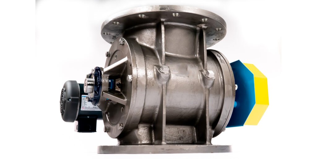
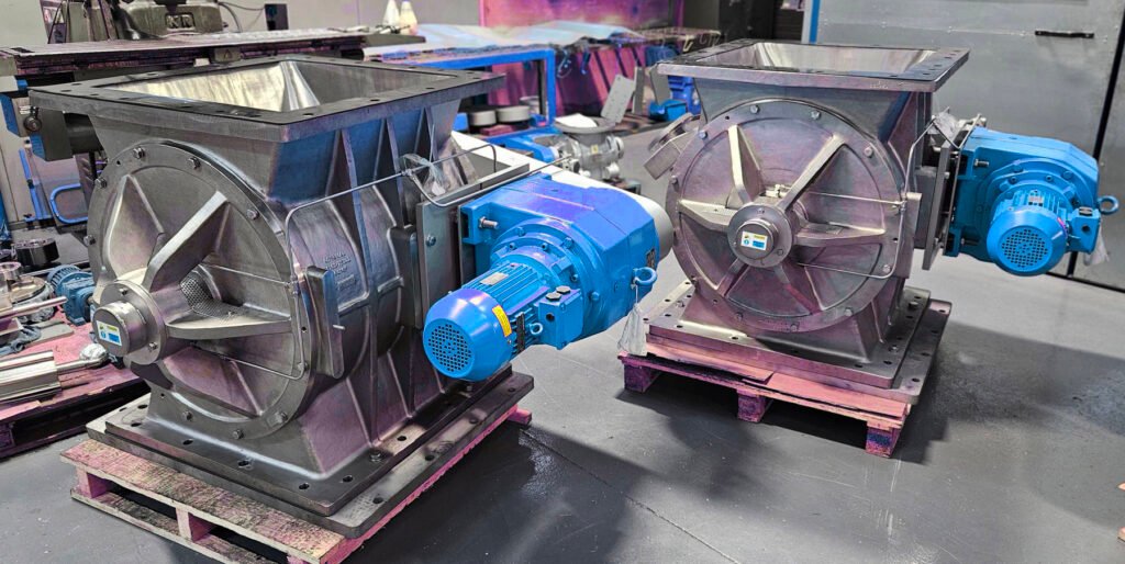
The main structural components of a rotary valve include the valve body, rotor, blades, shaft sealing system, and drive device. The valve body is usually made of cast iron, carbon steel, or stainless steel, with different materials and surface treatments selected according to the application environment; the rotor is designed with straight blades, inclined blades, or curved blades to adapt to the characteristics of different materials; the shaft sealing system uses a sealing device with a special structure to prevent dust and gas leakage . Advanced rotary valve products, such as variable frequency adjustable pre-divided rotary valves, also use a controllable variable frequency motor drive, and are designed with adjustable baffles and feed curtains in the hopper. By adjusting the angle of the adjustable baffle, the size of the hopper volume can be changed, thereby achieving precise flow control. This type of valve is usually also equipped with an intelligent monitoring system that can monitor parameters such as speed, temperature, and vibration in real time to achieve fault warning and preventive maintenance. The description of these components is as follows:
Rotary valve body
The valve body is a horizontal cylindrical structure with top inlet and bottom outlet, and is enclosed on both sides by vertical baffles. The valve body is typically constructed from metals such as cast iron, carbon steel, stainless steel, or aluminum, although other materials are used in specialized applications, such as those involving extremely high temperatures or highly abrasive solids. The interior surface of all cylindrical valve bodies is polished or chrome-plated to maintain the required close clearance between the valve body and rotor. A 2B surface finish is preferred.
The valve rotor is welded steel or stainless steel with eight or more grooves. Its horizontal shaft is also made of steel or stainless steel.
The entire valve is designed to withstand the maximum and minimum pressures and temperatures to which it is subjected, including process and environmental conditions.
The valve bottom can have an open or closed space between the rotor and the valve body. An open bottom allows solids that might have entered the gap between the rotor end and the valve body to fall out. Open-bottom rotary valves are not suitable for conveying solids into positive pressure conveying systems because they allow conveying air to flow upward into the gap, increasing the possibility of conveying air leakage. These valves can be used in vacuum conveying systems (such as airlocks) or as feeders. In most pneumatic conveying applications, closed-bottom rotary valves are more commonly used because they provide a better air seal between the rotor edge and the valve body.
To convey coarse particles such as plastic pellets, straight-through rotary valves feature a strategically designed inlet moldboard at the inlet section. This moldboard prevents solid particles from entering the gap between the rotor and valve housing, thereby preventing the rotor from getting stuck or seizing. This V-shaped moldboard, cast or welded onto the downstream side of the rotary valve inlet, guides solid particles into the rotor cavity.
Rotor
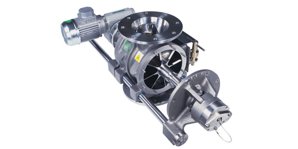
The rotor is a welded structure with rectangular blades welded to the shaft. The blades are evenly spaced around the rotor, forming triangular slots. The slot bottom can be flat or curved, depending on whether the solids are free-flowing or sticky.
The minimum number of blades for any size rotary valve is 8. Large valves, such as those with a flow rate of 4 cubic feet per revolution or more, may have 10 or 12 blades.
The blade tips are typically hardened with Stellite or tungsten carbide to reduce wear. When handling abrasive solids, such as plastic pellets, the trailing edge of the tip is typically backed off at a 45-degree angle to prevent particles from becoming trapped and causing the rotor to become stuck inside the valve body.
The rotor can be open or closed at both ends. Open rotors have a completely open rotor cavity. Closed rotors have a fully enclosed rotor cavity, welded to full-length plates at both ends. The blades are welded to the shaft and to both end plates, providing strength and rigidity to the rotor. Therefore, closed rotors are more robust and durable than open rotors and are less likely to bend under high differential pressures. They are suitable for a wide range of materials. Open rotors are less expensive, but are more susceptible to bending and rubbing against the inner surface of the valve body, causing wear and corrosion.
In canned rotors, the gap between the end plate and the valve housing is typically about ½ to ¾ inch.
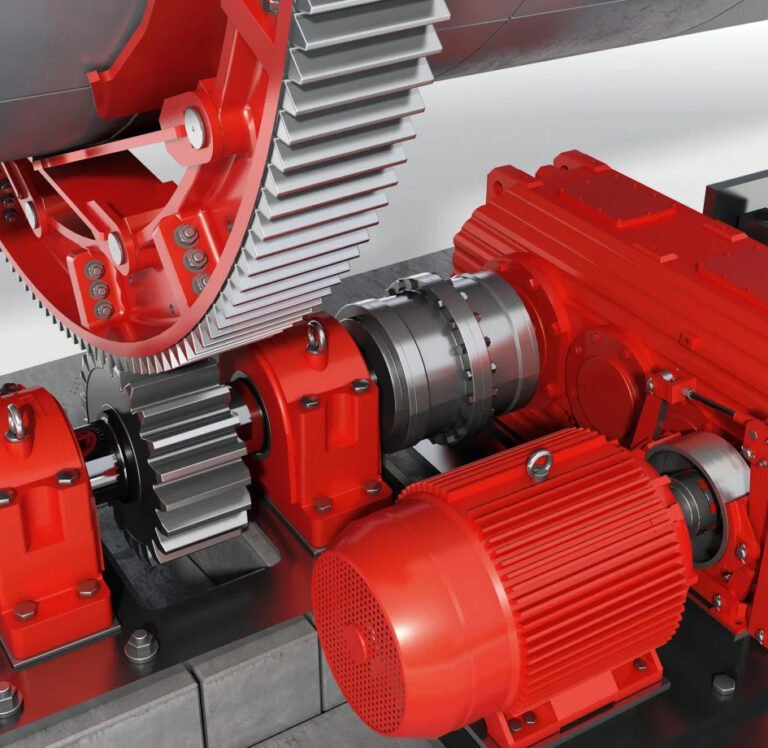
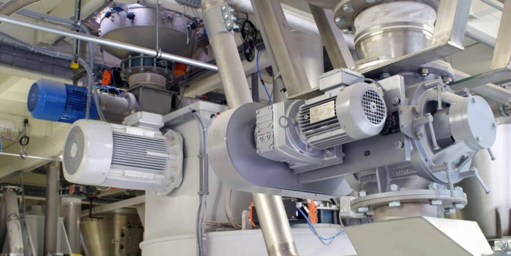
Rotary valve drive
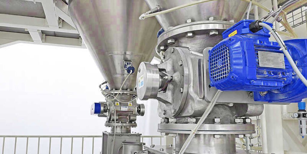
Rotary valves are typically driven by a gearbox motor rather than a separate motor and gearbox because this approach is more economical. The gearbox motor reduces the output speed to approximately 30 rpm. The rotary valve rotor passes through this motor, driven by a chain and sprocket to achieve the desired valve speed. The motor can be mounted at right angles to the rotary valve or parallel to it. Parallel installation with a chain and sprocket drive is preferred because the valve speed can be easily changed by replacing the sprocket. A right-angle installation is more difficult because it requires replacing the worm gear to change the speed.
The rotary valve shaft extends beyond the valve body side plate and uses an outboard spherical roller bearing with dust seals between the shaft and the valve body. Shaft packing is typically made of a wear-resistant material such as Teflon and neoprene washers. The normal speed range for rotary valves is 15 to 22 rpm. For rotary valve sizes, 16 rpm is commonly used.
Rotary valves used in continuous production operations are equipped with a zero-speed motion switch mounted on the driven shaft to detect chain breakage and the resulting stoppage of the valve.
Technical classification and performance characteristics of pneumatic conveying rotary valves
Pneumatic conveying rotary valves can be divided into various types according to different classification standards. Based on the working principle, they can be divided into dilute phase conveying rotary valves and dense phase conveying rotary valves; based on the structural form, they can be divided into straight-through rotary valves and side-entry rotary valves; based on the sealing technology, they can be divided into ordinary type and gas-sealed type; based on the drive method, they can be divided into electric, pneumatic, and hydraulic types.
| Classification Criteria | Valve Type | Main Features | Advantages | Limitations | Applicable Scenarios / Industries |
| How it works | Dilute Phase Conveying Rotary Valve | High-speed airflow (12–40 m/s), the material is conveyed in a suspended state | Suitable for light, non-abrasive materials; efficient transport; prevents settling | Not suitable for abrasive or fragile materials due to particle attrition | Pneumatic conveying of powders like flour, plastic pellets, chemical powders |
| Dense Phase Conveying Rotary Valve | Low-speed airflow (2–12 m/s), the material forms a plug or dense flow | Reduces material degradation, handles fragile or abrasive materials | Gentle conveying reduces breakage; lower wear on pipeline | Requires higher pressure system and more energy | Cement, minerals, fragile food powders, abrasive chemicals |
| Structural form | Straight-through Rotary Valve | Simple structure, easy maintenance | Low cost, easy to clean and maintain | Limited sealing performance; not for high-pressure systems | General industrial powder feeding and discharge (grain, feed, plastics) |
| Side Entry Rotary Valve | Side-mounted design with good sealing performance and small space occupation | Saves installation space, good sealing | Limited capacity compared to large straight-through designs | Space-constrained plants, compact conveying systems | |
| Sealing technology | Ordinary Rotary Valve | Provides basic sealing, suitable for low-pressure differences | Cost-effective, widely available | Leakage may occur in high-pressure systems | General working conditions with standard powders |
| Airtight Rotary Valve | Gas seal, extremely low leakage rate, can handle high pressure differences | High reliability in precision systems, minimal leakage | Higher cost, requires precise installation | Chemical plants, pneumatic conveying with pressure difference, high-value powders | |
| Drive mode | Electric Rotary Valve | Driven by electric motor, precise control and fast response | Automation-friendly, accurate flow regulation | Power-dependent, may not be suitable for explosive atmospheres | Applications requiring accurate dosing and flow control (pharma, chemicals, food) |
| Pneumatic Rotary Valve | Air-driven, with explosion-proof performance and strong power | Safe in flammable/explosive environments; durable | Air supply required, more maintenance on pneumatic parts | Coal handling, petrochemical plants, explosive powder transport | |
| Hydraulic Rotary Valve | Large torque and smooth operation, handles heavy loads | Can drive large-capacity valves; stable operation | Requires hydraulic system; higher cost and complexity | Heavy industry, cement plants, steel mills, bulk material handling |
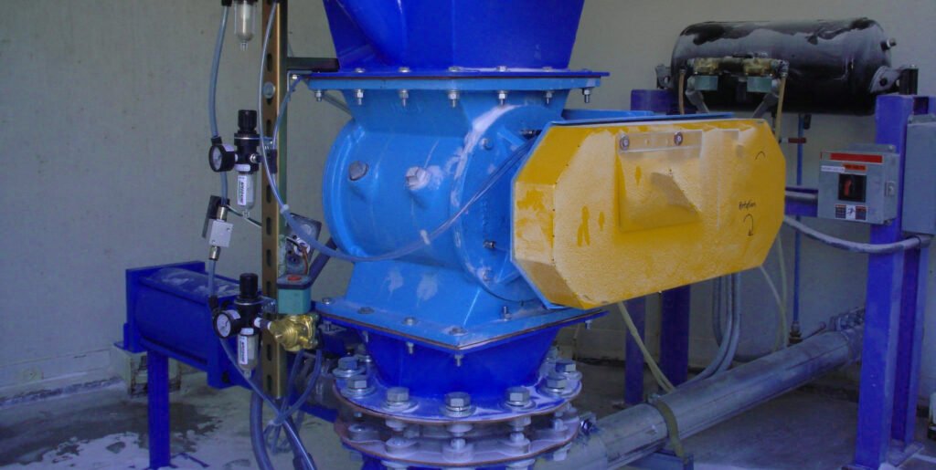
A dense-phase pneumatic conveying rotary valve system typically includes a compressor, cooler, water separator, starting silo, variable-frequency adjustable pre-splitting rotary valve, end silo, and conveying pipelines. This system conveys materials at low speeds and high concentrations, offering advantages such as a low power index, low airflow velocity, and high load ratio. It effectively addresses the high power consumption, easily shattered materials, and high dust generation associated with traditional pneumatic conveying.
Dilute phase conveying rotary valves are suitable for conveying many non-sensitive and non-abrasive powders or bulk materials. They typically utilize vacuum or positive pressure conveying systems, requiring sufficiently high gas velocities (typically greater than 20 m/s) to maintain suspension and deliver the powder to a receiving hopper. This type of rotary valve system offers advantages such as low investment, simple configuration, and minimal installation space. Output capacity can be flexibly adjusted by controlling the rotary valve's rotational speed.
The working principles of different types of rotary valves are as follows:
- Straight-through rotary valves : The solids inlet and outlet are vertically aligned and typically equal in size. As the rotor begins to rotate, solids flow vertically downward from the hopper above the valve, filling the empty rotor cavity. These valves can have square, rectangular, or circular inlets and outlets; square shapes are more common because they provide a larger opening area than circular openings.
- Side-entry valves : The solids inlet is offset 30 degrees from the vertical solids gravity flow line. This offset allows the incoming empty rotor pocket to only partially fill as the rotor rotates past the valve inlet. This partial filling minimizes shearing of solid particles that can sometimes become trapped between the rotor and valve housing. Partial filling also prevents solid particles that can sometimes become trapped between the rotor and valve housing from clogging or jamming the rotor. The volumetric fill efficiency of the empty pocket depends on the solids flow characteristics but is typically approximately 60%. These valves should have an adjustable slide on the inlet section to allow for increased or decreased pocket fill.
- Purge Valves : Similar to straight-through valves, they install directly into the conveying line without any intermediate devices. In this design, conveying gas enters from one end of the rotary valve, blows through the evacuated rotor pocket, and carries solids to the other end of the rotary valve, directly into the conveying line. This type of valve is suitable for highly viscous materials that are difficult to remove from the rotor pocket.
When are rotary valves used in industry?
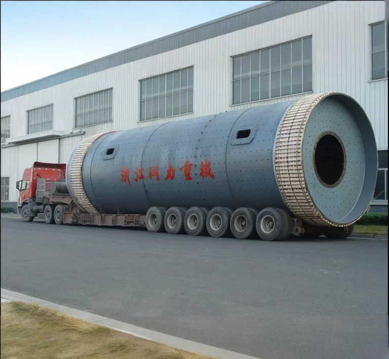
As a key component in pneumatic conveying systems, rotary valves are widely used in cement ball mill industrial sectors, ranging from general industry to specialized industries with stringent hygiene and safety requirements. Different applications have varying requirements for rotary valve performance, materials, and structure, driving the diversification and specialization of rotary valve technology.
The rotary valve has the following functions:
- Control and maintain a given product flow rate
- Maintain gas pressure difference between inlet and outlet
- Acts as explosion barriers, flame barriers, and process isolators
Industries that use rotary valves include:
- Agriculture, pharmaceuticals, and pet food
- Biomass, Power Generation and Waste-to-Energy
- Coal, minerals and chemicals, aggregates, asphalt and cement
- Food, Cereals, Dairy, Baking & Milling
- Paper, paints, plastics and powder coatings
- Steel mills, foundries, rubber mills, textile mills, tobacco mills, and lumber mills
Rotary valves have the following main industrial applications :
Emptying the silo
Rotary valves are installed beneath silos, hoppers, or other containment systems. They are used to control the discharge of bulk solids from these units and to feed equipment such as screw conveyors, flexible screw conveyors, pneumatic conveyors, and mixers.
Cyclone discharge
A rotary valve can also be installed below the cyclone separator. This creates a pressure seal between the storage system and the conveying system, ensuring a uniform flow of material from the outlet.
Dust removal process
Dust collection systems utilize rotary valves for dust removal. Rotary valves are used to transfer material from a pressurized point, such as a dust collector, to a non-pressurized point, such as a drum or silo. Rotary valves seal pressurized systems, preventing loss of air volume and pressure. This allows dust to be captured in the hopper, silo, or bin and returned to the material handling or conveying system.
Mixing and batching process
The rotary valve controls the rotor speed of the airlock, enabling volumetric measurement of powdered and granular bulk materials.
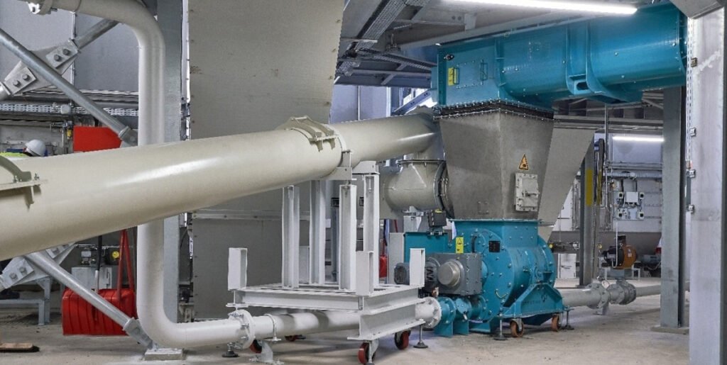
Material pneumatic conveying system
Rotary valves are also used to feed pneumatic conveying lines from hoppers, silos, cyclones and big bag discharge stations. This helps prevent air leaks in the conveying lines while maintaining a constant supply of powders or granules.
Air Lock Pneumatic Conveyor
Rotary valves can also assist pneumatic conveyors in feeding from silos, hoppers and screw feeders, moving bulk material into an airlock and then on to other equipment. This allows rotary valves to be used as airlocks for pneumatic conveyors.
Analysis of application fields of rotary valves
Pharmaceutical and food industries
In the pharmaceutical industry, rotary valves are used to transport APIs and intermediates, placing extremely high demands on valve materials, surface treatment, and sealing performance. Stainless steel, mirror-polished surfaces, and fully sealed designs are typically required to ensure compliance with GMP standards and hygiene requirements. Rotary valves used in the pharmaceutical industry are often equipped with CIP (clean-in-place) and SIP (sterilization-in-place) capabilities, enabling cleaning and sterilization without disassembly to prevent cross-contamination.
Rotary valves in the food industry are used to convey food ingredients such as flour, sugar, milk powder, and starch, and must also meet stringent hygiene and food safety requirements. Food-grade rotary valves typically utilize non-toxic materials, easy-to-clean designs, and structures that prevent material accumulation, ensuring no contamination of food. Statistics show that the food and beverage industry accounts for 35% of pneumatic conveying rotary valve applications, making it one of the largest applications for rotary valves.
Chemical and building materials industries
The chemical industry is a key application area for rotary valves, handling a variety of materials, including plastic pellets, fertilizers, and soda ash. Chemical rotary valves must be corrosion-resistant, wear-resistant, and explosion-proof to handle a wide range of corrosive and hazardous chemicals. Especially for abrasive materials, rotary valves require wear-resistant materials and specialized coatings to extend their service life and reduce maintenance requirements.
In the building materials industry, rotary valves are used to convey materials such as cement, fly ash, and mineral powder, which are often highly abrasive and have high bulk densities. These rotary valves require heavy-duty designs, wear-resistant liners, and reinforced blades to withstand the wear and impact of harsh operating conditions. Furthermore, due to the high throughput required, rotary valves in this industry often feature large capacities and high durability to meet the demands of continuous, large-scale production.
Other industrial fields
Rotary valves are also widely used in the power industry (transportation of fly ash and bottom slag), the metallurgical industry (transportation of high-temperature materials such as alumina, coke powder, and mineral powder), the plastics industry (transportation of polyethylene, polypropylene, and PVC powders), and the new energy industry (transportation of positive and negative electrode materials for lithium batteries).
In particular, rotary valves solve the transportation challenges of high-value, easily contaminated cathode and anode materials in lithium battery production. In the biomass energy sector, rotary valves enable efficient processing of biomass fuels such as straw and sawdust. These emerging application areas place demands on rotary valves for higher precision, stricter cleanliness, and more specialized materials, driving the continuous innovation and development of rotary valve technology.
| Application Areas | Main conveying materials | Key requirements | Technical Features | Market share |
| pharmaceutical industry | APIs and intermediates | GMP standards, sterile, pollution-free | Stainless steel material, mirror polishing, CIP/SIP function | About 28% |
| Food industry | Flour, sugar, milk powder | Hygienic standards, non-toxic, easy to clean | Food grade material, anti-accumulation structure | About 35% |
| Chemical Industry | Plastic pellets, fertilizers | Corrosion-resistant, explosion-proof, and wear-resistant | Special alloy, explosion-proof design, wear-resistant coating | About 15% |
| building materials industry | Cement, fly ash | Wear-resistant, large capacity, high strength | Heavy-duty design, wear-resistant lining, reinforced blades | About 12% |
| Other industries | Diversity | Customized according to material characteristics | Professional and personalized design | About 10% |
How Rotary Valves Keep Your System Running Smoothly
Pressure maintenance and airlock functions
The primary function of a rotary valve in pneumatic conveying is to act as an air lock. Maintaining a constant pressure differential between different zones in pressure and vacuum systems is crucial. A rotary valve prevents air leakage while allowing material to be transferred from one zone to another. This air lock function is crucial to system efficiency, as any loss of air pressure reduces material flow and increases energy consumption.
Adjust material feed
Rotary valves are designed to control the flow of material into conveying lines, ensuring a consistent feed rate, which is crucial for the stability of pneumatic conveying processes. Whether handling fine powders or larger particles, rotary valves regulate the delivery of the right amount of material, preventing blockages or interruptions. This controlled feeding not only increases system efficiency but also improves product quality by maintaining a consistent material flow.
Material handling versatility
These valves are versatile enough to handle a wide range of materials, including abrasive, sticky, or brittle substances. Made of durable materials, rotary valves can withstand the wear and tear associated with conveying a wide range of bulk materials. Their adaptability makes them ideal for industries such as food processing, pharmaceuticals, chemicals, and cement, where diverse materials are frequently conveyed. This ability to manage a wide range of materials without sacrificing performance is a key reason for their widespread use in pneumatic conveying systems.
Reduce system downtime
The reliability of rotary valves is crucial to minimizing downtime in pneumatic conveying operations. Designed for durability and long service life, rotary valves utilize precision machining and high-quality materials, reducing the need for frequent maintenance or replacement. This reliability lowers operating costs and reduces downtime, keeping conveying systems running smoothly for longer. Furthermore, these valves' ease of maintenance and parts replacement further enhances their effectiveness in minimizing system disruptions.
Improve energy efficiency
Rotary valves play a significant role in improving the overall energy efficiency of pneumatic conveying systems. By maintaining an effective air lock and regulating material flow, these valves optimize energy use within the conveying process. Efficient operation reduces the amount of air required to convey material, thereby lowering energy consumption. This energy efficiency is particularly important in large-scale operations, where energy costs can significantly impact profitability.
Customization for specific applications
Rotary valves can be customized to meet the unique needs of various pneumatic conveying applications. They can be designed with different rotor configurations, sealing options, and materials of construction to handle specific types of bulk materials. This customizability ensures that rotary valves perform optimally in any application, whether conveying abrasive powders in a cement plant or fine particles in a pharmaceutical factory. The ability to tailor rotary valves to specific needs enhances their effectiveness in ensuring the reliability and efficiency of pneumatic conveying systems.
Rotary Valve Technical Challenges and Countermeasures
Despite the continuous development of rotary valve technology, practical applications still face many technical challenges that require manufacturers and users to jointly address. These challenges involve energy consumption, wear, material handling, system stability and other aspects.
High energy consumption problem
Pneumatic conveying systems typically consume 20-40% of a plant's total energy consumption, making them a significant operating cost factor. For rotary valves, this energy consumption primarily comes from drive motor power, system leakage losses, and airflow resistance.
To solve the problem of high energy consumption, the following strategies can be adopted:
- Adopt variable frequency drive technology: the speed of the rotary valve is controlled by the frequency converter, and the power output is adjusted according to the actual material processing volume to avoid excessive energy consumption.
- Optimized rotor design: Computational fluid dynamics (CFD) and discrete element method (DEM) analysis are used to optimize the geometry of the rotor and valve cavity to reduce airflow resistance and energy loss.
- Improved sealing performance: Use advanced sealing materials and sealing structures to reduce gas leakage, maintain system pressure, and improve energy efficiency.
- Utilization of excess pressure and energy recovery: Consider energy recovery mechanisms in system design, such as utilizing the excess pressure of exhaust gas for auxiliary transportation or power generation.
Wear problems
Rotary valves face severe wear issues when handling abrasive materials such as cement, mineral powder, and fly ash, particularly at the rotor blade tips, valve body inner wall, and shaft seal areas. Studies have shown that over 70% of pipeline leaks are caused by elbow wear. When conveying highly abrasive materials, the lifespan of a typical rotary valve may be less than six months.
Strategies for addressing wear and tear include:
- Use wear-resistant materials: Use high-chromium cast iron, tungsten carbide coating or ceramic lining and other wear-resistant materials to make vulnerable parts to extend service life.
- Design replaceable parts: Design wear-prone parts into replaceable modules to reduce maintenance costs and downtime.
- Optimize air flow parameters: Reduce the impact and wear of materials on the inner surface of the valve body by reducing the conveying speed and adopting dense phase conveying method.
- Apply surface treatment technology: Use surface strengthening technologies such as thermal spraying and laser cladding to improve the surface hardness and wear resistance of key components.
Material property change issues
The performance of rotary valves is significantly affected by material properties. Changes in material properties such as bulk density, particle size distribution, moisture content, adhesion, and abrasiveness can directly impact conveying efficiency. For example, low-density materials (such as flour) are easily conveyed in a dilute phase, while high-density materials (such as cement) are best conveyed in a dense phase. Highly hygroscopic materials require controlled dew point, and abrasive materials require wear-resistant measures.
Strategies for addressing changes in material properties include:
- Develop adaptive designs: For example, use a rotary valve with adjustable volume to change the hopper volume by adjusting the baffle angle to adapt to different material characteristics.
- Pretreatment of materials: Pre-drying, particle size control or surface treatment of materials to improve their fluidity and conveying characteristics.
- Flexible system design: Design a rotary valve system with a certain adaptability range, which can handle materials with varying characteristics within a certain range.
- Real-time monitoring and adjustment: Install an online monitoring device for material characteristics to automatically adjust the rotary valve operating parameters based on the test results.
Common problems and solutions for air lock rotary valves
| observe | Possible root causes | Possible actions |
| Performance below design | The bag is not completely filled. The product has poor fluidity and the hopper design above the star valve is unreasonable. The product is blocked before reaching the valve. | This problem can be solved by using a discharge aid in the hopper. |
| Performance below design | The bag is not completely filled. If a valve is used to feed a pressurized delivery line, air leakage can fluidize the product at the inlet of the star valve, preventing it from filling the bag. This can be caused by improper valve specifications (excessive clearance), an insufficient number of vanes, or valve wear (clearance exceeds specification). Another possible root cause is not properly venting the empty bag before it reaches the hopper to pick up powder again. Finally, another possibility to consider is air seal flushing: if the pressure is set too high, air leaking through the seal can hinder flow. | Check the valve specifications to understand the pressure drop it must overcome. Check the venting of the valve and the hopper above (if any). Check the pressure of the compressed air seal. Note: Airlock rotary valves can be designed with 6, 8, or 10 blades. A higher number of blades results in a tighter valve. However, too many blades also reduce the valve's capacity: a sweet spot needs to be found between tightness and pocket volume. |
| Performance below design | The bag isn't emptying properly. Poor bag emptying is related to the flow properties of the powder. If the powder is too sticky, it can actually become trapped in the bag of the airlock rotary valve, reducing the volume available for new product with each rotation. | Some rotors are designed with a flat bag bottom where powder cannot accumulate and is more likely to fall out of the bag. |
| Damage caused by metal/metal contact | Star valve "scraping" occurs when metal-to-metal contact occurs, which can damage the rotor and stator. This can cause the valve to become blocked, rendering it unusable. Metal shavings can also be released into the product stream, which can be a problem for some applications. | To prevent this type of damage, it is necessary to: - Make sure no foreign matter comes into contact with the valve (use screens and magnets in front of the valve) - Make sure the valve is correctly sized, especially for the operating temperature, as higher temperatures can cause metal expansion and lead to valve contact - Train personnel to maintain the valve, as most equipment damage is related to improperly putting the rotor back into the valve after maintenance - Use a rotor/stator contact detection system If damage occurs, the valve will need to be re-machined, or if the clearance is too large after machining, the valve will need to be replaced completely. |
| Wear [IAC] | Rotary valve wear corresponds to medium- to long-term damage to the valve. Two main phenomena can cause wear in rotary valves: - Material is trapped between the vane tip and the housing during rotation - Air leaks, carrying product particles at high speed, erode the valve. It is possible to estimate which phenomenon is responsible for damage to a particular valve: If the housing is damaged on the load side (filled pocket), the first phenomenon is likely to be the cause; if the housing is damaged on the other side (empty pocket), the second phenomenon is likely to be the cause. | The following measures can be taken to prevent wear on air-lock rotary valves: - Select appropriate clearances to reduce the potential for product to be trapped between the rotor and stator. This also reduces air leakage that can cause erosion. - Use slotted blade tips to reduce the potential contact surface with entrained product during rotation . - Use a canned rotor (the rotor is enclosed on the sides, which limits leakage and avoids friction—but not all applications are suitable for this design). |
Conclusion
Rotary valves are essential components of pneumatic conveying systems, playing a key role in maintaining pressure, controlling material flow, handling a wide variety of materials, reducing system downtime, improving energy efficiency, and offering customization options. Their importance in promoting smooth and efficient operations cannot be overstated. Whether it's cement, food, or chemicals, choosing the right valve can increase productivity and reduce costs. As industries across the globe increasingly rely on pneumatic conveying for material movement, rotary valves will continue to play a central role in achieving optimal performance and operational efficiency.