


Introduction:
For a long time, Girth gear and small gear(pinion)transmission has become the mainstream choice of rotary incineration kiln drive mode due to its structural stability. Although this mode of transmitting torque through gear ring meshing has supported decades of industrial development, it has always faced bottlenecks that are difficult to break through - the manufacturing precision requirements of the huge gear ring are stringent, resulting in high processing costs; the continuous wear caused by meshing transmission not only increases the burden of frequent maintenance, but also aggravates equipment loss in harsh environments of dust and high temperature. However, when most people still anchor their cognition in this traditional mode, friction transmission technology has quietly completed the subversive reconstruction of the incinerator rotary kiln drive system. This innovative solution with friction as the core of power transmission realizes torque transmission through the close contact between the active friction wheel and the drum belt(riding ring), completely getting rid of the inherent limitations of gear meshing. It not only greatly reduces manufacturing and maintenance costs, but also redefines the efficiency standard of rotary kilns with more stable power output and more adaptable to complex working conditions.
Why Friction Drive rotary kiln incinerator is more suitable for hazardous waste?
Compared with gear transmission, friction transmission is more suitable for hazardous waste treatment for four main reasons:
Adaptability to Harsh Environments:
First, in the extremely harsh environment of high temperature, corrosion and high dust during the incineration of hazardous waste, gear transmission is prone to tooth surface deformation, erosion, wear and other problems due to its reliance on precise meshing, and the risk of transmission failure is high; while friction transmission transmits power through surface contact, has no meshing clearance, is less affected by dust and corrosive substances, and has a more stable structure.
Load Fluctuation Resistance:
Second, in the face of the complex composition of hazardous waste and the sudden load changes that are prone to occur during incineration, the rigid meshing of gear transmission has no buffer, and overload can easily cause serious failures; friction transmission has the characteristic of "overload protection", and the friction wheel will slip briefly when the load exceeds the limit, which can reduce the risk of downtime and ensure stable operation.
Better Sealing Performance:
Third, in terms of sealing requirements, the meshing of gear transmission is difficult to be completely sealed, and there is a risk of leakage; the friction transmission has a simple structure, and the contact parts can be effectively sealed through the sealing cover to reduce the leakage of toxic gases, which meets safety and environmental protection standards.
More Efficient Maintenance:
Fourth, from the maintenance perspective, the friction transmission has fewer components, a simple structure, easy replacement of wear parts, and no need for a complex lubrication system, making maintenance safer and more efficient. The lubrication system of gear transmission is susceptible to contamination, and replacement of the gear ring is time-consuming and easily exposes personnel to dangerous environments, posing a high risk of operation and maintenance.
Compare to Girth Gear Pinion Drive What are the adventages of friction drive rotary kiln?
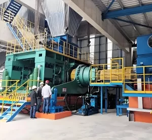
Think of a rotary kiln where the usual mechanical headaches—like tyre migration, shell deformation, and constant lubrication—are completely engineered out of the equation. That’s the innovation behind the ZJTL 2 Base rotary kiln also known as frictional drive incineration rotary kiln. Instead of the traditional design where the kiln shell rests rigidly inside fixed riding ring, the ZJTL 2 base kiln are driven by self-adjusting rollers instead of girth gear and pinion. These rollers automatically align with the natural movement of the kiln, allowing the tyres to rotate without causing friction or wear against the kiln shell. The result? No contact, no wear, and no need for lubrication. Unlike conventional kilns that rely on a gear and pinion to rotate the shell, the ZJTL Friction kiln employs a direct friction drive system. The kiln is powered by the rotation of the support rollers, which grip the tyres and smoothly drive the entire kiln. This method simplifies the drive mechanism, reduces maintenance, and increases overall efficiency.
So, In essence, the friction drive kiln achhieves high production capacity with minimal energy and space. The two-base design saves on construction time and costs and this rotary kiln never needs kiln axis alignment. Pyroprocessing with proven operational reliability.
Easy Maintenance: It is so simple
All parts are visible
Unlike conventional rotary kilns that rely on rigid, complex structures prone to wear and misalignment, the ZJTL Frictional drive kiln uses a unique suspension system that ensures exceptional mechanical stability and long-term performance. Because the kiln shell is supported by tangentially suspended tyres and self-adjusting rollers, the system naturally compensates for operational stresses. This design not only prevents uneven loads and excessive wear, but also keeps the entire assembly perfectly aligned — regardless of foundation settling over time. In other words, there’s no need for routine kiln axis realignment, which is often a costly and time-consuming process in traditional setups.
Easy Maintenance:
When it comes to maintenance, the ZJTL friction incinerator keeps things simple. There are no hidden or hard-to-reach components — everything is fully visible and accessible, making inspections faster and safer. No girth gear also means fewer moving parts, less lubrication, and lower risk of mechanical failure. Combined with a minimal number of support rollers, this drastically reduces the need for routine servicing and spare parts, leading to significantly lower maintenance costs over the kiln’s lifetime.
Automatic hydraulic thrust roller to keep it in place 24/7
We took a smarter approach. The friction kiln is equipped with an automatic hydraulic thrust device that actively manages the kiln’s axial position. This system continuously monitors and adjusts the position of the kiln using hydraulic pressure, keeping the shell precisely centered without manual intervention. Even under full axial load conditions, the HTD alone can handle the forces involved — eliminating the need for roller skewing entirely. That means less wear on your rollers, more consistent operation, and easier alignment throughout the kiln’s lifecycle. In short, the hydraulic thrust device makes axial control fully automatic, highly accurate, and virtually maintenance-free — all while protecting critical components and reducing downtime.
Patented graphite sealing ensure thermal efficiency
Even the most advanced rotary kiln is only as efficient as its seals-especially at the inlet and outlet ends, where airtight performance is critical. Why? Because when false air infiltrates the system, it dilutes combustion, increases fuel demand, reduces kiln temperature, and ultimately drives up operational costs while cutting down on clinker output. That’s why the 2 base friction kiln features a highly engineered sealing system using dual-layer graphite seals. These aren’t just ordinary seals-they’re built with precision. Two offset rows of graphite blocks are arranged in a staggered configuration, tightly held in place by a tensioned wire rope system. This design creates a flexible yet highly effective barrier between the high-temperature interior and the external air, ensuring minimal leakage and maximum thermal efficiency. One more smart advantage: at the kiln inlet, the shell rotates at relatively low speeds. This slower motion reduces the swirl and entrainment of dust particles, resulting in cleaner airflow, lower energy losses, and less wear on internal components. The result? Lower fuel consumption, easier operation, and more stable process control. In short, our design your seals don’t just close gaps — they seal in performance.
What are the benefits of a 2 base support roller friction drive rotary kiln?
2 Base friction drive rotary kiln saves on space, costs
More isn’t always better, even the most advanced rotary kiln is only as efficient as its mechanical design allows-and when it comes to structural layout. Traditional multi-base kilns are supported on three or more piers, introduce unnecessary complexity, cost, and maintenance headaches. Why? Because with each additional support point, you increase the risk of misalignment, thermal distortion, and mechanical stress-all of which can compromise long-term performance. That’s why the two-base friction drive rotary kiln has become the preferred solution for modern clinker production and waste incineration, especially in high-output lines producing Portland cement PO42.5 and hazardous waste incineration. Instead of relying on three or four sets of support rollers and piers, the two-base design uses just two support stations-one at the inlet and one at the outlet-to carry the entire load of the kiln shell. This is not a compromise in stability, but rather an engineering advancement that leverages a more rigid, self-aligning structure. Why does it matter? Because each extra base in a rotary kiln means:
- More concrete and steel during construction
- More points where thermal expansion must be compensated
- More alignment inspections, corrections, and long-term mechanical wear
By eliminating these extra variables, the two-base kiln:
- Reduces civil construction costs by 15–20%
- Speeds up installation time by up to 2 weeks
- Requires no periodic realignment throughout its service life
- Lowers long-term maintenance costs due to reduced mechanical wear
The result is a rotary kiln that’s easier to install, cheaper to operate, and more stable under thermal load-even at production rates of 2500–5000 TPD. In fact, the simplified support structure also leads to more predictable shell flexing, which improves refractory life, enhances heat retention, and helps maintain consistent clinker quality-all while using less fuel per ton of output. In other words, the two-base design isn’t just about saving space — it’s about engineering out inefficiency and designing a kiln system that delivers smoother rotation, lower maintenance, and better performance with fewer moving parts.
Friction drive incineration kiln has self-aligning roller!
Even the strongest rotary kiln shell can't perform without a drive system that delivers consistent torque and stress-free rotation. In many traditional cement clinker kiln setups, uneven load distribution and misalignment between support rollers and the kiln shell create chronic mechanical issues from pitting and spalling to cracks that cut short the life of both components and bearings.That’s why the Tongli friction drive kiln is built differently. At its core is a direct electro-mechanical drive system, no gear and pinion, no chain and sprocket. Instead, torque is transmitted directly through the support rollers using friction, eliminating backlash and gear misalignment. This streamlined design results in greater mechanical efficiency, lower maintenance demands, and smoother, quieter operation. But what truly sets the ZJTL 2 base friction kiln apart is its self-aligning roller support system. Here’s why it matters: during normal thermal cycling, a rotary kiln shell expands, contracts, and flexes. If the support rollers are rigid and fixed, even small deviations in alignment or load can lead to massive stress concentrations. Over time, this results in surface pitting, ovality in the shell, and even fractures in the riding rings. The ZJTL Friction kiln avoids this completely. Its fully suspended support rollers are mounted in self-aligning bearings that automatically compensate for kiln movement and shell deflection. This ensures:
- Continuous full-surface contact between the shell and rollers
- Even load distribution across the entire roller width
- Minimized axial thrust and reduced roller wear
- Longer refractory life due to reduced shell ovality
With only two base supports, the kiln rides smoothly, evenly, and efficiently — no stress concentrations, no realignment downtime, and no unnecessary bearing replacements. For cement plants producing Portland cement PO42.5 at high daily capacity, the ZJTL friction drive and roller system ensures stable torque transmission, lower total operating costs, and dramatically improved equipment longevity. In short, it’s not just a rotary kiln — it’s a fully integrated mechanical system designed to work with the kiln shell, not against it.
No lubrication required between tyre(riding ring) and kiln
Most rotary kilns rely on the steel tyre to transmit rotation and support the load-but in many older designs, that relationship comes at a cost. The interface between the tyre and kiln shell often demands constant lubrication to prevent excessive friction, galling, or seizure, especially during thermal expansion. It’s messy, time-consuming, and prone to failure if not meticulously maintained.That’s exactly the problem the ZJTL-Friction rotary kiln was engineered to eliminate. In this system, kiln rotation is driven purely by friction-not between gears, but between the support rollers and the kiln tyre. This friction drive mechanism transmits torque efficiently without the need for large girth gears or complex power transmission assemblies. But here’s where the real innovation lies: the tyre is not rigidly fixed to the shell. Instead, a floating tyre attachment system allows the tyre to move radially as the shell heats up and expands during operation. This design enables natural thermal breathing -the shell can expand and contract freely without generating stress concentrations or frictional binding at the tyre interface. So what’s the result?
- No lubrication is needed between the tyre and shell — no graphite blocks, no greased pads, no risk of dry-running damage
- Zero risk of shell cracking due to restrained thermal expansion
- Longer tyre and shell lifespan due to reduced mechanical wear
- Less maintenance labor and no downtime for tyre lubrication systems
By letting the tyre ride freely on the kiln shell, the system achieves a perfect balance: tight enough to transfer the vertical load through the rollers, but loose enough to prevent radial stress. And because the drive is located on the roller, not the shell, the result is clean, quiet, efficient rotation that reduces energy losses and mechanical complexity. For high-performance Portland cement PO42.5 production lines and waste hazardous incineration-where uptime, thermal stability, and long component life are essential-this friction-driven, lubrication-free solution is more than just a convenience. It’s a strategic upgrade in kiln mechanics that enhances reliability and simplifies plant operations.
Automatic realignment Friction drive kiln
In many conventional rotary kiln installations, periodic realignment isn’t just routine-it’s essential. As the foundation settles over time or thermal expansion shifts the kiln shell, even the smallest deviations in axis alignment can lead to shell ovality, uneven roller wear, and accelerated refractory damage. And with large multi-base kilns supported by three or four piers, this problem is only magnified. But the ZJTL-friction rotary kiln was designed to eliminate this maintenance burden altogether. Thanks to its two-base support system and friction drive mechanism, the ZJTL-friction maintains a naturally self-aligning axis-one that stays true without the need for continuous correction. There’s no girth gear, no pinion adjustment, and no complex torque transmission system that can shift over time. The result?
- No periodic axis realignment required
- Lower long-term maintenance costs
- Reduced wear and stress on support rollers and bearings
- Improved refractory life due to uniform internal pressure distribution
And because there’s no girth gear or pinion to worry about, there’s also no gear backlash, no tooth alignment, and no lubrication-related failures — just smooth, reliable rotation supported by precision-engineered rollers and a perfectly balanced kiln axis. In short, this is not just about convenience — it’s about designing a rotary kiln system that’s inherently resilient, self-stabilizing, and built for uninterrupted clinker production.
Friction drive Incineration kiln seals require no greasing
Rotary kilns operate under extreme thermal and mechanical stress-expanding, contracting, rotating, and shifting slightly every hour they’re in service. One of the most overlooked sources of inefficiency in this dynamic system? False air infiltration at the kiln inlet and outlet ends. When ambient air seeps into the system, it cools down the combustion zone, increases fuel consumption, disrupts airflow balance, and reduces overall kiln efficiency. That’s why the ZJTL-friction kiln uses a smarter approach: graphite sealing systems that are built for flexibility, durability-and freedom from lubrication. Unlike traditional seals that require constant greasing, tightening, and inspection, these graphite seals are engineered to maintain a tight, adaptable barrier between the kiln shell and the stationary inlet/outlet housing. The flexible graphite blocks are spring-loaded and arranged in a staggered dual-ring configuration. As the kiln rotates and shifts with thermal expansion, the seals automatically follow the movement, maintaining consistent surface contact and airtight performance. Here’s why this matters:
- No greasing is required — ever
- Zero friction-based wear on the seal surfaces
- Practically maintenance-free, with multi-year service life
- Reduced false air infiltration, which means lower fuel costs and more stable flame profiles
The operators also benefit from longer refractory life in the kiln hood and outlet zones, since the sealing system reduces cold air penetration and thermal shock. And with no need for lubrication systems or grease fittings, there’s fewer components to inspect, fail, or replace — making the kiln easier and safer to operate.
All the friction drive rotary kiln transmission parts are visible
What you can’t see often becomes what costs you most. Hidden wear, inaccessible components, and overly complex assemblies lead to reactive maintenance, unplanned downtime, and higher operating costs-especially in high-temperature, high-throughput environments like Hazardous waste incineration and portland cement PO42.5 production. Unlike traditional kilns that rely on multiple girth gears, complex drive arrangements, or enclosed lubrication systems, the ZJTL-friction features a streamlined, two-base design with fewer components-and all of them fully visible and easily accessible. Every key mechanical part-from the support rollers and thrust devices to the seals, shafts, and bearings is exposed for fast inspection, easy servicing, and real-time condition monitoring.
Why does visibility matter?
Because when maintenance teams can see wear before it becomes failure, they can plan ahead, reduce spare parts inventory, and avoid emergency shutdowns. No hidden housings. No gear covers to disassemble. No internal alignment tools or special jigs required. Just simple, robust components you can check at a glance, while the kiln is operating or during routine stoppages. Here’s what this visibility delivers:
- Lower maintenance costs through proactive inspections
- Reduced downtime, since parts are easy to access and replace
- Fewer components, meaning fewer failure points
- Faster training and safer operation for maintenance personnel
In high-capacity cement clinker production lines, where uptime is everything and shutdowns cost thousands per hour, the ability to visually verify the condition of critical components without opening up enclosures or halting the kiln is a significant competitive advantage. And because the ZJTL-friction kiln already reduces complexity with its gearless friction drive, graphite dry seals, and self-aligning roller supports, the entire system operates with fewer wear points-making it not only more visible, but also more reliable. Now let's dive into the detail of the support roller friction drive system, see the strcuture and components.
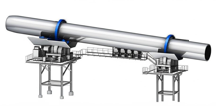
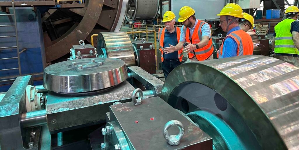
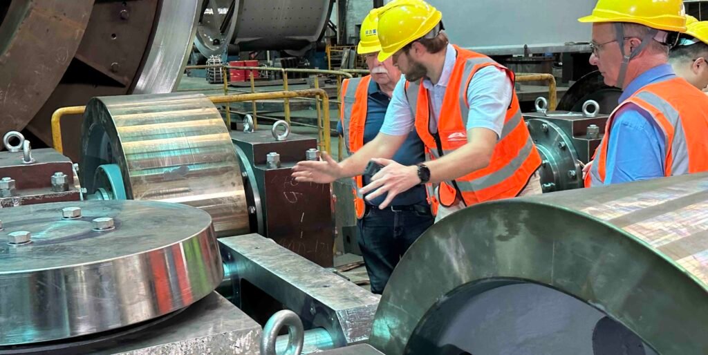
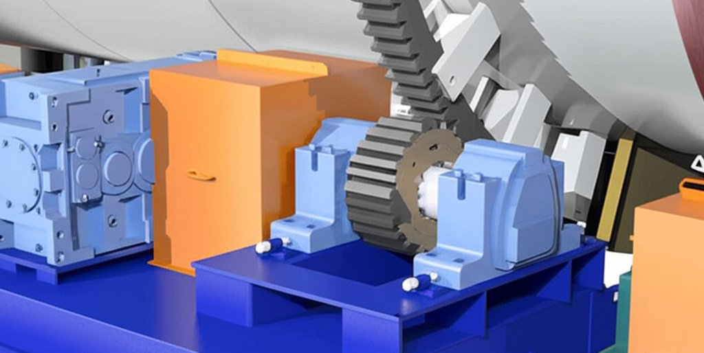
The friction drive assembly of a waste incineration rotary kiln
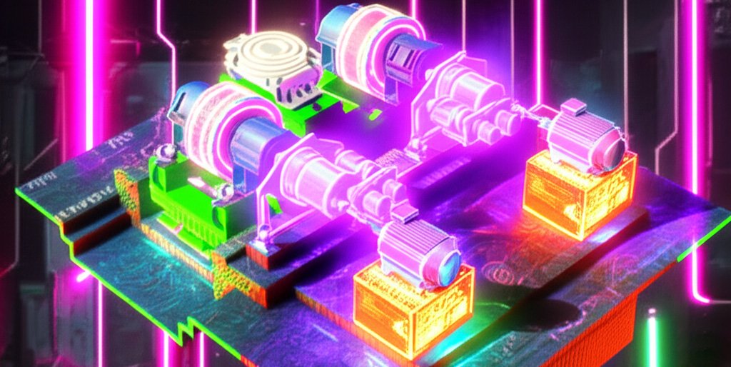
Take a look at the picture above — this friction support roller drive cad model is a little bit cyberpunk, but the structure of a two-base friction drive incineration rotary kiln transmission is quite clear. It consists of a motor, gearbox, support roller, and a shaft that runs through all three components, connected by couplings. Incineration kilns with this design are statically determinate, allowing rotation to be driven directly through the support rollers thanks to a specialized roller configuration. This innovation enables the use of friction drive systems, typically powered by AC variable frequency motors-a technology that is rapidly becoming the standard for all new two-support rotary kiln installations. One of the most significant benefits is the elimination of the traditional girth gear and pinion arrangement, along with its associated challenges: alignment difficulties, gear wobble, and the constant need for lubrication.By removing these components, the friction drive system simplifies the mechanical setup, increases reliability, and reduces long-term maintenance requirements. Furthermore, since the drive system is integrated into the kiln's support structure, no separate foundation is required, leading to substantial reductions in civil construction costs.
What are the components of a friction drive support roller system? structure in detail
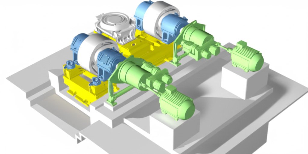
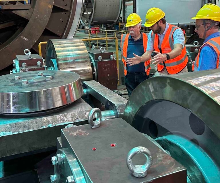
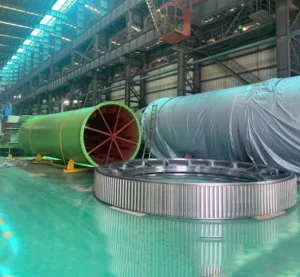
A friction drive support roller system is consisted of two main support rollers, both are motor-driven to rotate the kiln by direct surface friction with the kiln tyre. The rollers are mounted on self-aligning spherical bearings housed in adjustable frames that allow for thermal movement and precise load distribution. A variable frequency AC motor, often connected through a palntary gearbox and drive shaft, delivers torque to the drive roller. The kiln tyre, which rests on the rollers, is mounted loosely on the kiln shell to accommodate radial expansion without resistance. The system also include thrust rollers to prevent axial movement, and is supported by a heat-treated steel fabrication base frame that eliminates the need for large foundations.
1. Support Rollers (Drive Rollers)
Support rollers is everything of a friction drive rotary kiln system. It is fabricated from forged or cast alloy steel, the rollers are surface-hardened to withstand continuous contact with the incineration kiln tyre under high loads and temperatures. In a two-base friction kiln, both support rollers are motor-driven, serving not only to carry the full weight of the rotating shell but also to transmit torque through surface friction. These rollers are mounted on heavy-duty spherical roller bearings housed in adjustable support frames, allowing for self-alignment and thermal compensation which is critical for ensuring long-term durability.
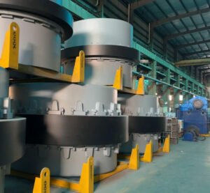
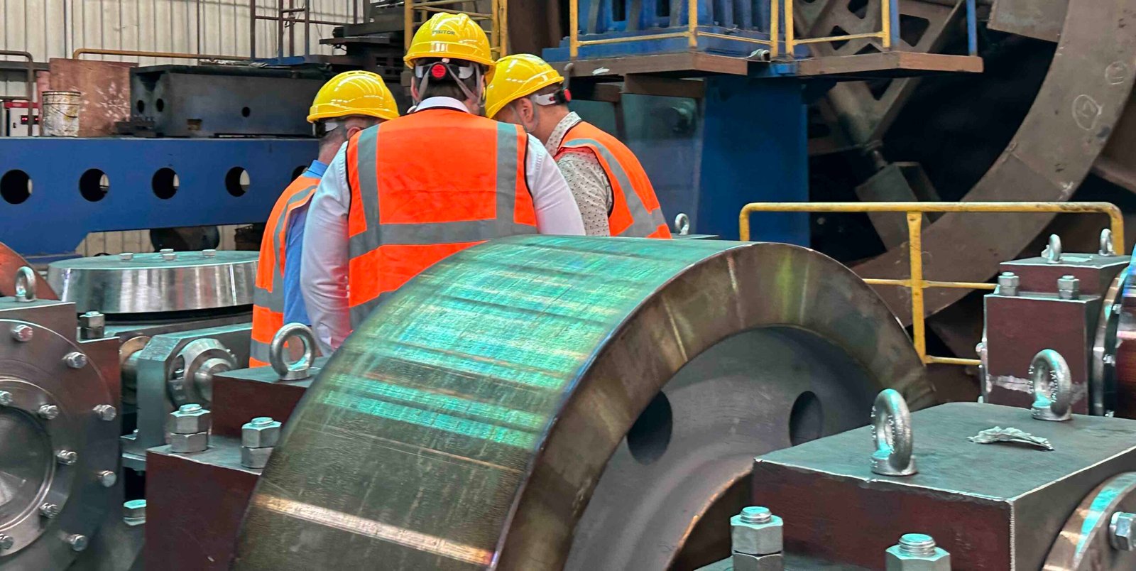
2. Tyres (Riding Rings)
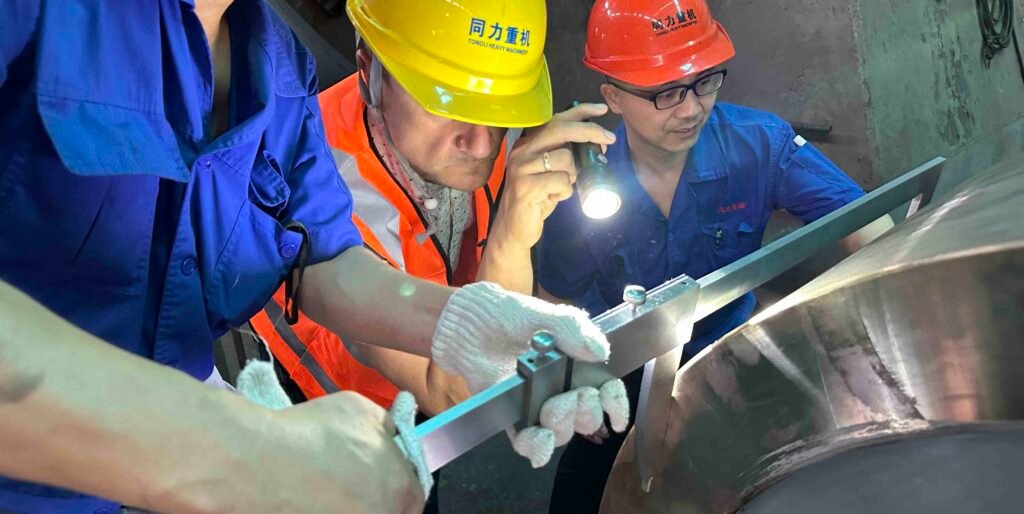
The kiln tyres, or we call riding rings, are large machined steel rings installed circumferentially around the shell at 2 locations head and tail. The function is to distribute the kiln's load onto the support rollers and provide the friction interface required for rotation. These tyres are machined using our CNC 10m vertical lathe with precise roundness and surface tolerances typically within ±0.3 mm over the diameter to ensure uniform contact and minimal slippage. We have designed“floating tyres,” affixed to the shell using radial key blocks and pads that allow independent thermal expansion of the shell without inducing stress.
3. Siemens Drive Motor
The drive motor is the heart of the friction drive system. Most modern rotary kilns employ AC motors with variable frequency drives (VFDs), enabling fine control over rotational speed and torque output. It is important for startup, steady operation, and shutdown. The motor is positioned adjacent to the drive roller and coupled via a direct or shaft-mounted gearbox. In high-capacity clinker kilns, motor outputs exceed 100 kW, depending on kiln size, material load, and process resistance, the power can be up to 500kw.
4. Gearbox aka reducer
The drive roller is not directly motor-driven becasue the motor spin too fast, a gearbox serves to reduce motor speed while amplifying torque. Helical or planetary gearboxes are used due to high efficiency, compact design, and robustness under fluctuating thermal and mechanical loads. The gearbox is mounted inline between the motor and the drive shaft, ensuring smooth power transmission. The reduction ratio is selected based on kiln diameter, length, and material resistance, falling in the range of 10:1 to 30:1 for incineration kiln applications.
5. Shaft
The drive shaft transmits mechanical power from the gearbox (or motor) to the support roller. It is forged and designed for torsional rigidity and minimal deflection, the shaft is precision-machined and often supported by pillow block bearings. Flexible or torsionally soft couplings are integrated to absorb misalignment, vibration, and thermal expansion movements.
6. Thrust roller
Thrust rollers are essential for controlling axial movement of the kiln shell during operation. While support rollers handle radial loads, thrust rollers prevent the kiln from drifting along its longitudinal axis due to shell slope or process-induced thermal expansion. It is adjacent to the support rollers on at least one pier, these rollers are angled or profiled to maintain the kiln in the correct position. Improper thrust control can result in excessive shell movement, uneven tyre wear, and mechanical instability.
7. Bearing housing and bearing
High-load SKF/Flange spherical roller bearings are employed to support the rotation of support rollers under heavy axial and radial loads. These bearings are housed in split-type steel or cast iron blocks, allowing easy disassembly for inspection or replacement. Centralized lubrication systems are integrated to ensure optimal bearing life under harsh operating conditions, with grease oil delivered through ports to reduce friction and thermal degradation.
8. Base frame for roller, gearbox, motor
The base frame support the entire roller assembly. Roller pedestals incorporate hydraulic jacks, spring-loaded assemblies, floating plates that facilitate automatic load equalization and shell alignment. The base frame itself is compact and rigid and gone through heat-treatment, minimizing space requirements and reducing civil foundation costs, part of the baseframe is grouted into the concrete foundation.
How does friction drive compare to a traditional girth gear and pinion drive rotary kiln? In number
Mechanical Configuration and Layout
In terms of mechanical layout, the girth gear and pinion drive system is more complex and heavier than a friction drive. It requires a large precision-mounted gear on the kiln shell, meshing with a motor-driven pinion, which adds to installation and alignment challenges. In contrast, the friction drive system uses motor-driven rollers to rotate the kiln through surface contact, eliminating the need for external gearing. This results in a more compact, lightweight design with fewer moving parts. While friction drives offer simplicity and reduced maintenance, girth gear systems remain better suited for larger, high-torque kilns due to their robust transmission capacity.
| Feature | Friction Drive | Girth Gear & Pinion Drive |
| Torque Transmission Method | Roller-to-shell surface friction | Gear mesh between girth gear and pinion |
| Drive Component Location | Below or beside kiln shell | Side-mounted girth gear and pinion |
| Component Count | Fewer components | More components (gear, pinion, base, etc.) |
| Layout Complexity | Simple, compact | Complex, bulky |
| Suitable Kiln Size | Small to medium kilns | Medium to large kilns |
| Installation Tolerance | Less critical | Very precise (gear runout, backlash, etc.) |
Drive Mechanism Complexity
In terms of drive mechanism complexity, friction drive systems are simpler and more compact. They consist of fewer components, motor-driven support rollers-making them easier to install, align, and maintain but the control system is more complex than traditional girth gear drive because if the 4 motor does not run at the same or at the same speed, then some roller spin faster that others, this will cause the rotary drum tumbling. On the other hand, girth gear and pinion drives involve multiple precisely aligned parts, including a large girth gear, pinion, shaft couplings, and lubrication systems. This adds to mechanical complexity and requires more maintenance over time. For small to medium kilns, friction drives offer clear advantages, while girth gear drives remain preferred for heavy-duty, high-capacity kilns.
| Feature | Friction Drive | Girth Gear & Pinion Drive |
| Main Components | Motor, gearbox, drive roller | Motor, gearbox, pinion, girth gear |
| Complexity Level | Low | High |
| Installation Difficulty | Easy | Complicated |
| Alignment Sensitivity | Moderate (roller pressure control) | High (gear-pinion meshing accuracy) |
| Maintenance Requirement | Low | High (gear wear, lubrication, shimming) |
Installation Time & Cost
| Feature | Friction Drive | Girth Gear & Pinion Drive |
| Installation Time | Short | Long |
| Labor Intensity | Low | High |
| Alignment Requirements | Basic (roller positioning) | Critical (gear runout, backlash) |
| Material Cost | Lower | Higher (girth gear, pinion, shimming) |
| Total Installation Cost | Low to Moderate | High |
Friction drive rotary kilns offer shorter installation time and lower costs due to their simpler structure and fewer components. With no girth gear to mount or align, setup mainly involves positioning the support rollers and drive motor, making it faster and less labor-intensive. In contrast, girth gear and pinion systems require precise alignment, machining of gear mounting surfaces, and careful assembly of the gear train, increasing both time and cost. While girth gear systems are essential for large kilns, friction drives provide a more economical solution for small to medium installations.
Initial Investment Cost
The mechanical investment cost for a friction drive rotary kiln is generally lower than that of a girth gear and pinion system. Friction drives eliminate the need for large machined gears, pinions, and associated mounting hardware, reducing both material and manufacturing expenses. The compact design also minimizes the need for complex foundations or high-precision alignment tools. In contrast, girth gear systems require costly gear fabrication, precision machining, and skilled assembly labor. These factors make girth gear drives a higher upfront investment, though they may be justified for larger kilns requiring high torque transmission, But we need to point out that the control system of the friction drive system is relatively expensive, becasue girth gear pionion drive does not need control, however the friction motor driven roller need a system to control the speed of each roller.
| Feature | Friction Drive | Girth Gear & Pinion Drive |
| Gear Components | None | Expensive (girth gear + pinion) |
| Motor and Transmission | Standard drive motor and gearbox | Higher-spec motor + gear alignment |
| Kiln Shell Modification | Minimal | Requires gear mounting surface |
| Installation Equipment Cost | Low | High (jigs, lifting, alignment tools) |
| Overall Investment Cost | Lower | Higher |
Torque Transmission Efficiency
Friction drive systems transmit torque through surface contact between rollers and the kiln shell, which can result in some slippage under heavy loads, slightly reducing transmission efficiency. This limits their use primarily to smaller or medium-sized kilns. Conversely, girth gear and pinion drives offer highly positive mechanical engagement, providing superior torque transmission with minimal loss. The precise gear meshing ensures reliable power transfer even under high torque demands, making girth gear drives the preferred choice for large, heavy-duty rotary kilns requiring maximum efficiency.
| Feature | Friction Drive | Girth Gear & Pinion Drive |
| Torque Transmission Method | Friction-based contact | Positive gear meshing |
| Slippage Risk | Moderate (depends on contact pressure) | Negligible |
| Efficiency Level | Moderate | High |
| Suitable Kiln Size | Small to Medium | Medium to Large |
| Reliability under Load | Limited | Excellent |
Kiln Shell Stress and Alignment Tolerance
| Feature | Friction Drive | Girth Gear & Pinion Drive |
| Kiln Shell Stress | Low due to friction contact | High due to mounted girth gear |
| Alignment Tolerance | Moderate, more forgiving | Very tight, critical for gear health |
| Risk of Shell Deformation | Low | Higher, especially if misaligned |
| Maintenance of Alignment | Easier, less frequent | Difficult, frequent monitoring needed |
Friction drive systems generally impose lower stress on the kiln shell because they transmit torque via rolling contact without heavy gear mounting. This reduces the risk of shell distortion and allows for more forgiving alignment tolerances. In contrast, girth gear drives require the installation of a large, heavy gear mounted precisely on the shell, which can introduce concentrated stresses and demands extremely tight alignment to avoid uneven wear or damage. As a result, girth gear systems require more frequent alignment checks and careful stress management.
Application Suitability (Cement vs. Waste Incineration)
Friction drive systems are often favored in waste incineration rotary kilns and smaller cement kilns due to their simpler design, lower cost, and easier maintenance, which suit the intermittent or variable operating conditions typical in waste processing. In contrast, girth gear and pinion drives are more common in large cement rotary kilns where continuous, high-torque operation demands robust, precise, and reliable torque transmission. The girth gear system’s durability and efficiency make it ideal for heavy-duty, large-scale cement production environments.
| Feature | Friction Drive | Girth Gear & Pinion Drive |
| Typical Industry Use | Waste incineration, small to medium cement kilns | Large cement kilns, heavy industrial use |
| Operating Conditions | Variable, intermittent load | Continuous, high torque |
| Maintenance Flexibility | Easier, suitable for less frequent service | Requires regular, skilled maintenance |
| Cost Sensitivity | Lower initial and running costs | Higher investment justified by scale |
| Reliability Demand | Moderate | High |
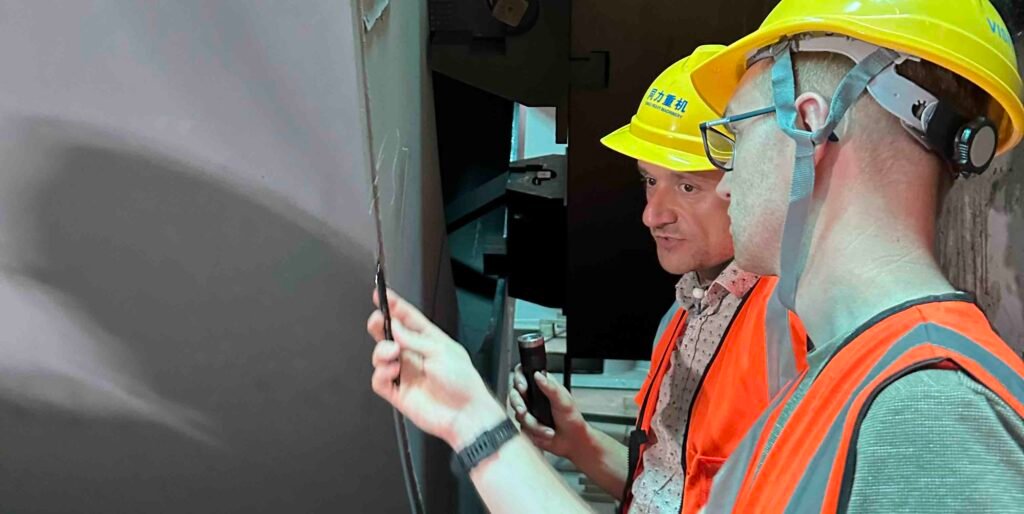
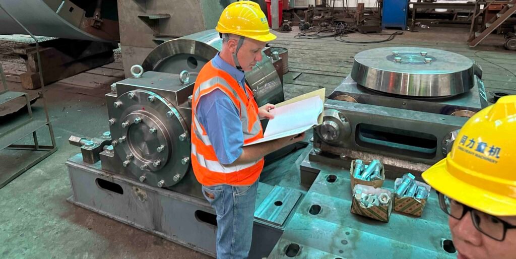
What is NDT Non-Destructive Testing of a hazardous waste Incineration rotary kiln?
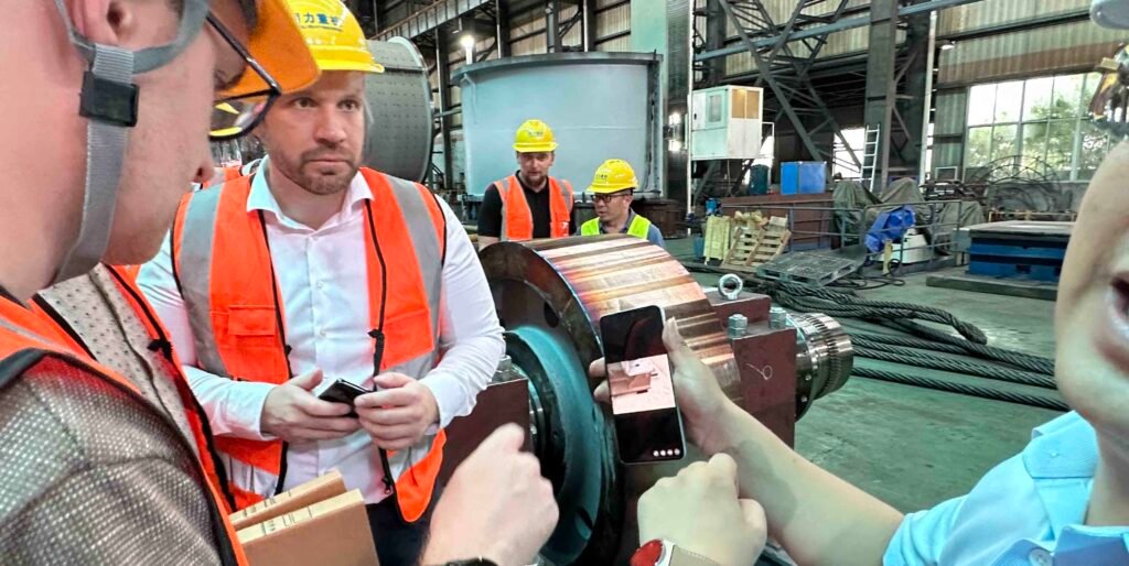
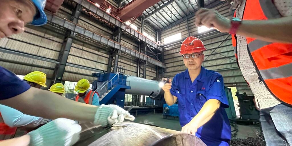
Why choose tongli hazardous waste incineration friction drive rotary kiln? Becase the quality is guaranteed. We performe UT PT MT to ensure the quality of our product. It helps prevent structural failure caused by high-temperature corrosion and mechanical stress. By identifying flaws before they become critical, NDT ensures the safe handling of toxic and hazardous materials under demanding operating conditions. Regular inspections also reduce the risk of unplanned shutdowns, thereby extending the service life of key components. Furthermore, NDT plays a vital role in maintaining compliance with CE and ISO environmental and safety regulations, supporting both operational reliability and regulatory accountability. If you are interested how we do the NDT test please check out this article here: 3 NDT method and process for hazardous waste incineration rotary kiln production
Key Components Subject to NDT in a Friction Drive Rotary Kiln:
Kiln Shell
- Methods: Ultrasonic Testing (UT), Magnetic Particle Testing (MT), Visual Inspection (VT), Radiographic Testing (RT)
- Purpose: Detect cracks, wall thinning, or weld defects due to high thermal cycling and chemical corrosion.
Support Rollers and Shaft
- Methods: UT, MT
- Purpose: Check for surface and subsurface cracks, fatigue, or improper wear that could affect drive efficiency.
Riding Ring (Tire)
- Methods: UT, MT, Dye Penetrant Testing (PT)
- Purpose: Ensure no fractures or deformations in the ring which is key to friction-based torque transmission.
Drive Rollers (Friction Rollers)
- Methods: UT, MT, VT
- Purpose: Assess wear, cracking, or surface hardening loss that could cause torque slippage or uneven rotation.
Weld Seams (Kiln Shell & Brackets)
- Methods: MT, PT, RT
- Purpose: Ensure weld integrity and absence of porosity, slag inclusions, or undercuts.
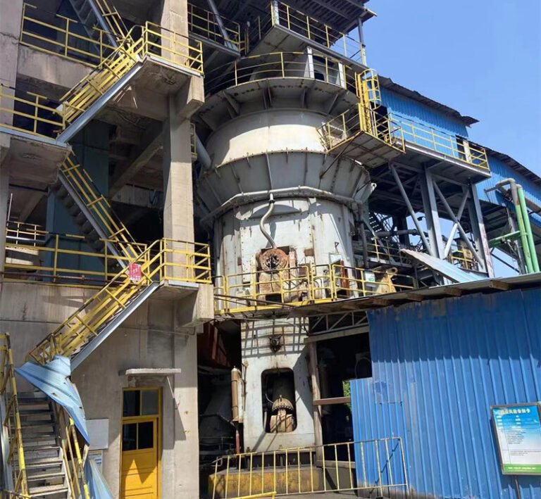
What is the step after the clinker calcination?
After the limestone gypsum and so on is crushed and calcined, it will pass on to the next step which is clinker grinding, so this is a advertisement for our own product vertical roller mill, just so you know, hope you like this ad.
Conclusion:
A friction drive transmission rotary kiln offers a reliable solution for processing hazardous waste, cement clinker, and limestone-especially in small to medium-scale operations. Its simplified mechanical layout and reduced maintenance demands make it particularly suitable for waste incineration plants and modular cement production lines. While it may not match the torque transmission efficiency of girth gear systems in heavy-duty cement applications, its flexibility, ease of installation, and operational stability under variable loads make it a smart choice for industries seeking cost-effective, environmentally focused kiln solutions. If you want to know more about the transmission of a rotary kiln we have wrote another article that introduces 3 types of kiln transmission type: chain spoket, friction, gear, please click the link here.