


Operating a fertilizer blending line is not simple!
Operating a fertilizer blending facility especially declining weigh blending system requires far more than simply combining raw materials to a target formula. For a plant owner, the key questions are whether the facility can consistently hit formulation tolerances, respond quickly to changing blend specifications, control material losses, and achieve the designed annual throughput with predictable operating costs. Poor operational decisions such as improper material flow design, inadequate weighing control, or mismatched loading systems often lead to segregation, off-spec blends, excessive rework, and lost margin. This guide is written for blending plant owners and investors, and focuses on the practical operational principles that determine long-term performance: how materials should be handled and metered, how blending accuracy is maintained under real operating conditions, how capacity is managed during peak seasons, how to troubleshoot, and how the facility should be operated to balance flexibility, reliability, and cost efficiency. So now let's start with step 1 preparation.
How to operate a fertilizer blending plant?
(Screening → Batching & Weighing → Blending → Packaging) now we will introduce each process one by one.
Preparations
Before the day of blending: check the following things:
- Confirm that the approved production order (product name, grade, batch size, bag weight) matches the formula loaded in the control system.
- Verify that the batching mode (continuous or batch) is correctly selected in the PLC/control system.
- Ensure tolerance limits for weighing and blending accuracy are correctly set.
Check Raw Material Condition & Suitability
- Check raw materials for particle size compatibility (especially for 2–4 mm BB fertilizer requirements).
- Confirm raw materials are dry, free-flowing, and not caked, as moisture can affect weighing accuracy and blending uniformity.
- Verify that incompatible materials (e.g. high-hygroscopic or dusty fines) are identified and handled according to process requirements.
- Ensure raw material storage bins and hoppers are clean and free of residual material from previous batches.
Equipment & Mechanical Readiness
- Inspect all conveyors, elevators, and mixers for abnormal noise, vibration, or obstruction.
- Confirm belt tension, tracking, and proper lubrication of rotating components.
- Check that screening equipment is fitted with the correct mesh and is undamaged.
- Verify that all safety guards and covers are correctly installed.
Screening Operation Procedure: Material Screening and Classification(optional)
Raw materials are conveyed by belt conveyor to the rotary screening machine equipped with 2.00–4.00 mm screen mesh. Material within the specified particle size range is discharged and transferred to the batching and feeding section. Oversized lumps and fine particles separated during screening are collected and returned for reprocessing or handled separately according to plant procedures, ensuring downstream process stability and final product quality. (If your raw material are already granule and no bulk then no screening process is needed)
Batching and Weighing Safety Operating Procedure: Operator Safety Requirements
Operators must wear appropriate personal protective equipment (PPE) before entering the workstation. All rotating and transmission components must be fitted with intact safety guards. During equipment operation, inspection, cleaning, or maintenance is strictly prohibited, and foreign objects must not be allowed to enter the machinery to prevent equipment damage and safety incidents.
Batching and Weighing Process Operating Procedure
Pre-Start Inspection and Preparation
- Verify that all electrical and control components at the workstation are intact and functioning properly.
- Check the electronic weighing system for abnormalities and confirm weighing accuracy.
- Inspect lubrication conditions of all rotating equipment.
- Jog-test belt conveyors and start them after confirming normal operation.
- Coordinate with upstream and downstream stations and confirm readiness for production.
- Verify that all raw material types are complete and available in sufficient quantity.
Start-Up and Production Operation
Batching parameters shall be set strictly in accordance with the batching instruction sheet. The weighing system shall be calibrated and adjusted before production, and original production records must be completed in real time. Conveyors are then started to feed materials into the blending system. The mixing time shall not be less than 30 seconds, ensuring uniform blending of all components.
1. Zero Setting and Scale Calibration
- Set all batching, loss-in-weight, or electronic belt scales to the predetermined zero reference prior to production start.
- Confirm that hopper scales, platform scales, and bagging scales show zero with no load present.
- Perform a functional zero drift check; allowable zero deviation should not exceed ±0.1–0.2% of full scale, depending on design accuracy.
- Record zero calibration values in the shift start-up log for traceability.
2. Micronutrient System Preparation (If Applicable)
- Set the micronutrient impregnation or dosing system (powder, granular, or liquid type) to its predefined zero and calibration point.
- Verify that micronutrient feeder accuracy meets design tolerance (typically ±0.5–1.0% for minor ingredients).
- For liquid micronutrients: 1. Confirm that dosing pumps are primed. 2. Open feed nozzles or spray spouts. 3. Check for leakage or blockage.
- Ensure micronutrient systems are interlocked with the main blending control logic to prevent under- or over-dosing.
3. Raw Material Loading and Bin Management
- Load base fertilizer raw materials into the receiving hoppers using forklifts, loaders, or bag dumping stations.
- Fill storage bins to the recommended operating level (normally 70–90% of bin capacity) to ensure stable mass flow.
- Confirm raw materials: 1. Match the approved formulation. 2. Are free-flowing, dry, and within specified particle size range (typically 2–4 mm for BB fertilizer).
- Ensure bin level sensors and low-level alarms are functioning correctly.
4. Micronutrient Loading and Feeding Readiness
- Load powdered or granular micronutrients into dedicated receiving hoppers, ensuring segregation from base materials.
- Verify that feed screws, vibratory feeders, or rotary valves operate smoothly.
- For liquid micronutrients, confirm: 1. Proper atomization or spray pattern. 2. Uniform distribution across the fertilizer stream.
- Record micronutrient batch quantities for quality and traceability control.
5. Blending Machine Start-Up
- Start the blending machine (rotary drum mixer or paddle mixer) according to the programmed sequence.
- Verify: 1. No abnormal vibration, noise, or motor overload. 2. Mixer rotational speed is within the design range (commonly 15–25 rpm for rotary drum mixers, depending on diameter).
- Allow the system to reach steady-state operation before packaging begins.
6. Material Flow and Process Verification
- Visually inspect material movement from: Storage bins → feeders → conveyors → mixer.
- Confirm: 1. No bridging, rat-holing, or feeder starvation. 2. Continuous and balanced material discharge from each hopper. 3. Observe mixing behavior to ensure uniform blending without segregation.
Shutdown Procedure
Upon receiving a shutdown instruction, raw material feeding shall be stopped immediately. The equipment shall continue running until all residual material inside the system is completely discharged, after which the equipment may be shut down. After shutdown, thorough cleaning of equipment and the workstation shall be carried out to meet hygiene and safety requirements.
Packaging Safety Operating Procedure: Packaging Area Safety Control
Packaging operators must wear required PPE before work. Safety guards on all rotating and moving components must remain in place. During equipment operation, repair or cleaning activities are strictly prohibited to avoid injury and equipment damage.
Packaging Process Operating Procedure
Pre-Start Inspection
- Inspect all electrical equipment and confirm proper functioning.
- Check all rotating parts for smooth operation and adequate lubrication.
- Start the system and verify stable and normal equipment operation.
- Confirm that packaging bags, labels, and product type match the production batch.
- Ensure the power supply meets operational requirements.
- Coordinate with related workstations prior to start-up.
Packaging Operation
The finished product shall meet the requirement that ≥90% of particles fall within the 2.00–4.00 mm range. Prior to packaging, operators must carefully verify bag type, labeling, sealing quality, and ensure that each bag contains a product certificate or instruction sheet. Finished products shall be stacked neatly.
The average net weight per bag shall not be less than 50.0 kg or 40.0 kg, with a qualification rate of 100%. Any non-conforming material shall be returned to the raw material storage area for reprocessing.
Bagging System Start-Up
- Start the automatic or semi-automatic bagging machine simultaneously with stable blending operation.
- Verify bagging scale accuracy: 1. Typical bag weight tolerance: ±0.5 kg for 50 kg bags or as specified by local regulations. 2. Ensure correct bag type, size, and labeling are in use.
Bag Stitching and Sealing Operation
- Start the bag stitching or sealing machine in coordination with bag discharge.
- Check: 1. Stitch integrity and seam straightness. 2. Thread length control (typically 5–10 cm exposed tail). 3. Ensure no open, leaking, or improperly sealed bags proceed to stacking.
Bag Weight Verification and Quality Control
- Conduct manual bag weight checks at regular intervals (e.g. every 10–20 bags or every 15–30 minutes).
- Compare manual measurements with scale readings and adjust if deviations approach tolerance limits.
- Record inspection data in the quality control log.
- Immediately stop production and recalibrate if weight deviation exceeds allowable limits.
Packaging Shutdown
After receiving a shutdown notice, remaining material inside the mixer shall be fully discharged. Once stopped, equipment and surrounding areas must be thoroughly cleaned to maintain site order and hygiene.
Standard Operating Procedure (SOP) for Raw Material Handling Operator
- The computerized control system governs the entire BB fertilizer blending line. This position must be operated only by professionally trained and authorized personnel. Unauthorized or untrained personnel are strictly prohibited from accessing or operating the control system. The control room shall be restricted to authorized staff only. During normal production, the control system operator must not leave the workstation without permission.
- Prior to system start-up, the control system operator shall thoroughly inspect the system status to ensure all equipment and interlocks are in proper operating condition. After successful system start-up, the operator shall input the production formula for the current shift into the PLC/computer control system. Only after confirming the accuracy of the raw material formulation may materials be charged from each hopper into the batching and blending system.
- The control system operator is not authorized to modify or adjust production formulas. Any formula changes must be approved and implemented by designated technical or management personnel.
- During operation, the control system operator shall continuously monitor control instruments, process parameters, and dynamic material flow indicators, and perform necessary mode selection and functional operations in accordance with system requirements and operating instructions.
- Maintenance, inspection, and servicing of electrical and control equipment associated with this position shall be carried out exclusively by qualified electrical or automation technicians. The control system operator bears primary responsibility for the correct and standardized operation of the system during complete BB fertilizer blending production.
Standard Operating Procedure (SOP) for Raw Material Transportation Operator
- Under the supervision of the Production Manager and in accordance with shift leader instructions, the raw material handling operator shall carry out all raw material transport and feeding support tasks, ensuring smooth coordination with the BB fertilizer blending line.
- Raw materials shall be transported strictly in accordance with the approved formulation, including correct material type, grade, and required quantity. Any damaged or broken bags within a stack must be repaired or re-bagged to prevent leakage prior to handling, in order to avoid material spillage, cross-contamination, and material loss.
- Upon completion of material retrieval for each shift, the operator shall clean all spilled or residual materials from the storage and handling areas, restore proper stacking, and secure the material stacks with tarpaulins to protect against moisture, contamination, and environmental exposure.
- Before the end of each shift, the operator shall pre-stage an adequate quantity of raw materials (typically 3–5 metric tons) for the incoming shift, ensuring uninterrupted feeding and continuous operation of the bulk blending fertilizer production line.
- When applicable, the operator shall use appropriate material handling equipment (such as forklifts, pallet trucks, or hoists) in accordance with safety regulations, and promptly report any abnormalities, shortages, or material quality issues to the shift leader or control room.
Standard Operating Procedure (SOP) for Batching Operator
- Personnel responsible for feeding materials into the charging elevator shall operate under the supervision of the Production Manager, follow shift leader assignments, and perform all batching and feeding tasks under the oversight of the Quality Control (QC) inspector, ensuring compliance with BB fertilizer blending requirements.
- Raw materials shall be fed strictly according to the approved formulation, ensuring correct material type and dosing accuracy. During feeding, the operator shall remove and separately collect all foreign materials such as quality certificates, bag sewing threads, plastic liners, and other packaging debris. Any foreign matter accumulated on screens or grates shall be cleaned promptly to prevent contamination and equipment blockage.
- Empty raw material bags shall be sorted by material type, bundled in standard lots (50 bags per bundle), and returned to the warehouse after each shift in accordance with material management procedures.
- The operator shall continuously maintain cleanliness of the batching area by removing spilled materials, contaminated product, and debris. Prior to shift handover, a thorough housekeeping and sanitation cleaning must be completed.
- The batching operator has the authority and responsibility to stop the use of any non-conforming or suspect raw materials, and shall immediately report such cases to the shift leader, QC personnel, or production management for further disposition.
Standard Operating Procedure (SOP) for Finished Product Packaging Operator
- Under the supervision of the Production Manager, the weighing and bagging operator shall follow shift leader instructions and cooperate with Quality Control (QC) personnel, accepting random inspections of bag weight at any time to ensure compliance with BB fertilizer packaging specifications.
- The operator shall routinely inspect the accuracy of the weighing scale and perform calibration or zero adjustment as required. The operator bears full responsibility for the net weight of finished product bags produced during the shift, ensuring all bag weights meet specified tolerance and quality standards.
- The operator shall verify the correctness of product certificates or inserts used during the shift, including product grade, formulation, production date, and shift identification. After receiving each bag, one product certificate or instruction sheet shall be placed on the top inside of every bag in accordance with product traceability requirements.
- The operator shall ensure that all product certificates (or instruction leaflets) match the packaging identification and product designation, and shall maintain consistency of labeling within each bundled set of packaging materials. If mixed or incorrect product types are found, they must be immediately separated and removed.
- The weighing and bagging operator has the authority to prevent unauthorized adjustment of electronic weighing scales and to reject or prohibit the use of non-conforming packaging materials, reporting such issues promptly to the shift leader or QC personnel.
Standard Operating Procedure (SOP) for Bag Sewing Operator
- Under the supervision of the Production Manager, the bag sewing operator shall follow shift leader instructions and cooperate with Quality Control (QC) personnel, accepting random inspections of bag weight and sealing quality at any time.
- Prior to each shift, the operator shall inspect the operating condition of the bag sewing machine and prepare all required accessories and tools, including sealing thread, sewing needles, oil can, lubricating oil, tweezers, cutting blades, and other necessary items, ensuring readiness for continuous packaging operation.
- The operator shall fold and stitch the bag mouth strictly in accordance with sewing standards. The folded edge and stitch line must be straight and uniform to prevent skipped stitches or seam failure that could result in bag opening. The exposed sealing thread length shall be controlled within 5–10 cm to ensure sealing integrity and consistent appearance.
- The operator is responsible for the issuance, proper use, and safekeeping of the bag sewing machine and all related tools and consumables, including needles, lubricants, sealing thread, tweezers, and blades.
- Under normal operating conditions, re-sewing of bags is not permitted. In special or abnormal situations, re-sewing may only be performed after approval from supervisory personnel.
- The bag sewing operator has the authority to prevent unauthorized use or improper handling of the sewing machine, sealing thread, and related equipment, and shall report any misuse or abnormal conditions to the shift leader or production management.
Standard Operating Procedure (SOP) for Warehouse Manger
- Under the supervision of the Production Manager and in coordination with the shift leader, the finished product handling operator shall carry out bag handling, stacking, and internal transport operations, ensuring smooth transfer of packaged BB fertilizer from the production line to the designated storage or dispatch area.
- Finished products shall be stacked in a stable and orderly manner according to site conditions and storage layout requirements. The bottom layer shall be placed with the bag face oriented downward to ensure pallet stability and protect printed markings. Bags with damage, leakage, defective stitching, or unclear packaging identification shall be promptly segregated and properly handled, preventing non-conforming products from entering the warehouse.
- Upon completion of stacking for each shift, the operator shall thoroughly clean all spilled materials around the stacking area, maintain site cleanliness, and cover the stacked products with tarpaulins to protect against moisture, contamination, and environmental exposure.
- Before the end of each shift, the operator shall cooperate with the finished product warehouse keeper to conduct accurate product inventory and reconciliation. After production is completed, the operator shall shut down the conveyor power supply and relocate handling equipment to designated areas in accordance with safety and site management regulations.
Standard Operating Procedure (SOP) for Maintenance Technician
- Under the supervision of the Production Manager, maintenance technicians shall carry out routine equipment inspection, preventive maintenance, and corrective repair work, ensuring the safe, stable, and continuous operation of the BB fertilizer blending line.
- Before production start-up and during production intervals, the technician shall inspect conveyor belt tensioning devices to confirm they are secure and functioning properly. The belt tension shall be appropriate, and the conveyor shall be checked for belt misalignment or tracking deviation. Any abnormal condition shall be corrected immediately to prevent equipment damage or production interruption.
- Both before and after each shift, the technician shall inspect all transmission components (including couplings, chains, belts, and drive units) to ensure smooth and flexible operation. Any stiffness, abnormal resistance, or irregular movement shall be eliminated without delay.
- The technician shall maintain cleanliness of equipment frames and surrounding work areas, keeping them free of debris and residual material. Prior to shift handover, a thorough cleaning shall be performed, ensuring no foreign material remains on equipment surfaces and no material build-up adheres to hopper walls. During production, key equipment shall be air-cleaned every two hours, with special attention to dust and debris on flow controllers, pulleys, and rotating components.
- During operation, the technician shall continuously inspect all bolts and fasteners, tightening any loosened components promptly. Reducers, motors, and bearings shall be monitored for abnormal temperature, noise, or vibration. In the event of overheating or abnormal operation, the equipment shall be stopped immediately and the fault eliminated before resuming production.
- The technician shall perform proper lubrication of all rotating and moving parts in accordance with the lubrication schedule, using specified lubricants to prevent premature wear and eliminate potential mechanical hazards.
Batch type blending plant what can go wrong?
Batch-type bulk blending fertilizer plant operates on a discrete production logic, where raw materials are weighed, mixed, discharged, and then the system is prepared for the next batch. Unlike continuous blending systems, each batch is produced as an independent quality unit. This means any error in weighing, mixing, cleaning, or control will directly affect the entire batch and cannot be averaged out or corrected later, making batch plants highly sensitive to accuracy, material quality, and operational discipline.
Batching and Weighing Accuracy Failures
In a batch blending plant, the batching and weighing system is the most critical section because it determines the final nutrient ratio of each batch. According to GB/T 21633-2022 for BB fertilizer, the batching accuracy must be controlled within ±1% for nitrogen, phosphorus, and potassium materials, and within ±2% for secondary and micronutrients. In real production, batch plants frequently experience single-material deviation or cumulative deviation across multiple materials, especially when raw material weights are wrongly calculated at recipe level or wrongly fed into the weigh hoppers. These deviations are commonly caused by feeder selection that does not match material characteristics, such as using large-pitch screw feeders for fine or powdery phosphate materials, which leads to bridging or sudden flushing. Field data show that under such conditions, phosphate batching errors can reach ±3.5%, far exceeding acceptable limits. Load cell calibration drift is another batch-specific risk. When zeroing and calibration are not performed regularly, sensor drift can cause potassium batching errors to rise from ±0.8% to more than ±2% after several hundred hours of operation. In addition, unstable bin levels at the start of each batch cause inconsistent material head pressure, leading to fluctuating feed rates and loss of batching precision.
Mixing Uniformity Not Meeting Specification
Mixing quality in batch plants depends entirely on whether the mixer can achieve full homogeneity within a fixed mixing time and batch volume. Industry standards such as NY/T 1113-2014 require a coefficient of variation (CV) of 5% or less after mixing. However, batch plants often fail to meet this requirement due to equipment wear, incorrect batch loading, or improper operating parameters. Wear of mixer paddles or ribbons is a major contributor. When paddle thickness is reduced by more than 30%, the convective and shear forces inside the mixer are significantly weakened, causing CV values to increase from acceptable levels around 3% to more than 7%. Batch fill ratio is another critical factor. Twin-shaft paddle mixers typically achieve optimal performance at 60–70% fill. Underfilling prevents effective material circulation, while overfilling creates dead zones. In some plants, operators intentionally overfill batches to increase output, pushing fill ratios above 80%, which has been shown to produce CV values exceeding 9%. Large differences in particle size between raw materials further aggravate this issue, causing segregation inside the batch and nutrient stratification after discharge. For more details about "How to ensure the mixing uniformity of a Bb fertilizer production line please click here."
Low-Quality Raw Materials and Misuse of Batch Mixers
A common misconception in fertilizer batch blending plants is that drum or paddle mixers can compensate for poor-quality raw materials. As a result, lumpy, moist, or low-grade materials are sometimes accepted into production. In practice, such materials introduce significant batch-specific risks. Lumps disrupt feeder stability and prevent uniform dispersion, while moisture levels above 1.5–2.0% promote hopper build-up and material adhesion on equipment surfaces. Low nutrient content raw materials amplify the impact of any weighing error, as even small deviations in mass translate into larger nutrient deviations in the finished batch. Because batch systems do not continuously correct formulations, the use of substandard raw materials often results in entire batches falling outside specification and being rejected.
Inadequate Cleaning Between Batches
Insufficient cleaning between batches is one of the most critical and distinctive problems of batch-type blending plants. When different blend specifications are produced sequentially, residual material remaining in the mixer, elevators, chutes, or bagging spouts can contaminate subsequent batches. This problem becomes particularly severe when switching between formulations with different micronutrient contents. Even a relatively small hold-up volume of 20–50 kg left in the system can cause nutrient deviations of 1–2% in the next batch, especially when batch sizes are limited to 2–3 tonnes. In batch operations, such cross-contamination cannot be diluted over time, making proper cleaning procedures essential for product consistency and regulatory compliance.
Continuous type blending plant What can do wrong?
Continuous fertilizer blending lines are designed to deliver high throughput, consistent nutrient accuracy. However, unlike batch systems, continuous plants are highly interdependent: a disturbance at any single point can propagate rapidly across the entire process. This article outlines the most common technical failure modes in continuous fertilizer blending systems—explaining why they occur, how they manifest, and what operational data typically reveals. So if are also deciding whether to choose a continuous or batch type blending please see our previous article: Batch Blending vs Continuous Blending: Which Suits Your BB Fertilizer Production Line?
1. Raw Material Flow Instability and Feeding Errors: Poor Material Flowability
One of the most fundamental problems is that raw materials do not flow freely. Fertilizer ingredients such as urea, MAP, DAP, potassium chloride, or micronutrient powders are sensitive to moisture, particle size distribution, and surface characteristics. common causes include:
- High moisture content leading to arching or ratholing in hoppers
- Fine powders (<1 mm) creating cohesive flow behavior
- Inadequate hopper wall angles or rough internal surfaces
When flow becomes intermittent, the downstream weighing and dosing systems receive unstable mass flow, resulting in nutrient deviations that cannot be corrected in real time.
2. Inconsistent Feeding Rate
Continuous blending relies on constant, repeatable feed rates. If raw materials are not fed at a stable speed, the blend ratio fluctuates immediately. Typical root causes:
- Variable-speed feeders affected by voltage fluctuations
- Poorly tuned variable-frequency drives (VFDs)
- Changes in material bulk density as hopper levels drop
Operational data from fertilizer plants shows that even a small feeder speed deviation (0.3–0.5 Hz on a screw feeder VFD) can translate into 8–10% mass flow fluctuation, which is already beyond acceptable nutrient tolerance for commercial blends.
3. Wrong Material Fed into a Calibrated Hopper
Another critical failure occurs when a hopper is loaded with a material different from what it was calibrated for. For example:
- A feeder calibrated for granular KCl is mistakenly loaded with fine MAP
- Bulk density and friction angle change, but control parameters remain unchanged
Since continuous systems assume constant material properties, this error can lead to systematic dosing bias, often unnoticed until laboratory analysis of the finished product.
4. Incorrect Blend Formula Programming
Human or software errors in recipe selection remain a frequent issue:
- Wrong NPK ratio selected
- Incorrect inclusion or exclusion of micronutrients
- Formula updated but not synchronized across all feeders
Because continuous systems do not segregate batches, entire production runs may be affected before the error is detected.
5. Mechanical Obstructions Affecting Weight Accuracy
Blockages or partial obstructions at any point especially near:
- In-feed hoppers
- Dynamic weigh feeders
- Bagging pre-weigh hoppers
Can cause false weight signals. This leads to incorrect feeder corrections and cumulative nutrient deviation across the line.
6. Feed Rate Synchronization Failure
Continuous blending plants typically use multiple synchronized dosing channels combined with online dynamic weighing. The stability of the final product depends on precise coordination between all channels. Therefore each dosing channel must respond at nearly the same speed to control commands. If one feeder lags then:
- Nutrient balance shifts immediately
- Overall blend accuracy deteriorates
Industrial operating data shows that when one feeder response time exceeds others by more than 100 ms, channel-to-channel flow deviation can exceed 10–12%, pushing nutrient content outside commercial tolerance limits.
7. Hopper Level Imbalance
Feeders depend on sufficient material head pressure. Best practice in continuous plants is to maintain hopper fill levels between 40% and 70%.
- If one hopper drops below ~20%:
- Material discharge pressure decreases
- Feed rate can drop by 15–20% even if the feeder speed remains unchanged
This asymmetry causes severe ratio imbalance. In real cases, potassium deficiencies of 15–20% below target have been recorded, forcing full rework of finished product.
8. Dynamic Mixing Uniformity Fluctuations and Segregation: Insufficient or Uneven Residence Time
Unlike batch mixers, continuous mixers rely on controlled residence time distribution. Typical design targets:
- Residence time: 18–25 seconds
- Stable axial flow without dead zones
If rotor or shaft speed is too high:
- Residence time drops below 10 seconds
- Incomplete mixing occurs
If speed is too low:
- Material accumulates locally
- Dead zones and back-mixing develop
Measured data shows that reducing mixer speed from 25 rpm to 15 rpm can increase the coefficient of variation (CV) of nutrient distribution from ~3–4% to 8–9%, which is clearly unacceptable for commercial fertilizer.
9. Particle Size and Density Differences
Continuous mixing systems are especially sensitive to segregation effects caused by:
- Large differences in particle size
- Large density contrasts
For example:
- Potassium chloride (density ~1.98 g/cm³, 2–3 mm)
- Urea (density ~1.33 g/cm³, 0.5–1 mm)
In continuous flow conditions, segregation rates can reach 15%, compared to ~5% in batch mixers, leading to layered discharge and nutrient stratification.
10. Wear of Internal Liners and Mixing Elements
As wear liners and paddles thin:
- Shear forces weaken
- Convective mixing efficiency declines
Field experience shows that when liner thickness loss exceeds 40%, mixing CV values can more than double, even if all operating parameters remain unchanged.
11. Continuous Conveying System Failures: Blockage
Blockages commonly occur at:
- Curved sections of chain or scraper conveyors
- Discharge chutes of bucket elevators
Examples from operating plants show:
- Insufficient chain tension leading to material accumulation
- Discharge chute angles below ~45° reducing gravity flow efficiency
Once material accumulation reaches ~30% of conveyor capacity, complete blockage is likely, resulting in multi-hour shutdowns.
12. Material Backflow
Backflow typically occurs at the mixer inlet when downstream flow is restricted.
- If discharge flow is lower than inlet flow:
- Internal pressure builds up
- Material is forced backward
Measured internal pressures exceeding 0.03 MPa have caused reverse flow rates of over 1 t/h, leading to contamination, waste, and unsafe working conditions.
13. Material Leakage
Leakage points include:
- Belt conveyor splices
- Scraper conveyor sealing plates
Under continuous operation:
- Belt splice tensile strength is typically only ~60% of belt body strength
- After several hundred hours, leakage rates of 3–5% are not uncommon if materials and sealing designs are inadequate
14. Wear Fatigue and Mechanical Component Failure in Continuous Operation: Transmission failure
Continuous blending lines often operate 7,000+ hours per year, far exceeding intermittent systems. High-risk components include:
- Gear reducers
- Couplings
- Drive motors
If gearbox oil temperature exceeds 90–95°C:
- Lubrication film breaks down
- Gear wear accelerates by a factor of 2–3
Coupling elastomers under continuous load may lose 40% or more of their elasticity, leading to misalignment, vibration, and premature bearing failure.
15. Rapid Wear of Material-Contact Parts
Wear rates strongly depend on material selection:
- Standard carbon steel screw flights may wear 4–6 mm per month when handling abrasive potassium salts
- Composite or hardfaced wear materials can reduce wear to <1 mm per month, extending service life by 5–6 times
Unchecked wear directly reduces dosing accuracy and mixing efficiency.
16. Electrical and Control System Synchronization Failures: Speed Synchronization Errors
Continuous plants depend on master–slave speed control across feeders. Problems arise when:
- VFD response times differ significantly
- Weight sensor signals are delayed
Signal delays exceeding 50 ms prevent real-time correction and can cause nutrient deviation swings of ±4% or more.
17. Incorrect Start–Stop Logic
Safe operation requires:
- Reverse-order startup (downstream → upstream)
- Forward-order shutdown (upstream → downstream)
Logic errors can cause:
- Empty running of mixers (“dry running”)
- Severe friction heating (>150°C)
- Accelerated wear and mechanical damage
18. False Overload Protection Trips
Continuous systems naturally experience current fluctuations of ±10%. If protection thresholds are set too close to nominal values:
- Normal fluctuations trigger shutdowns
- Production losses accumulate rapidly
Real-world cases show single false trips causing tens of thousands of dollars in lost output and cleanup costs.
Quick FAQ: How to Troubleshoot Operational Errors in a Continuous Fertilizer Blending Line
When nutrient deviation exceeds acceptable commercial tolerances, the investigation must start with feed-rate stability across all dosing channels. Each feeder’s actual speed should be monitored directly at the variable-speed drive level; frequency fluctuations greater than approximately 0.5 Hz indicate inadequate speed control, worn feeder elements, or poorly tuned drive parameters. In parallel, dynamic weighing systems must be checked for zero drift under no-load conditions. Even small zero offsets can translate into significant proportional errors during continuous operation. Finally, hopper inventory levels must be reviewed across all raw material bins. Continuous feeders depend on consistent head pressure, and when any hopper drops below roughly 20% fill level, discharge instability can occur even if the feeder speed remains unchanged. In well-documented cases, correcting these three factors has reduced single-channel dosing errors from over ±3% to below ±1%.
Excessive coefficient of variation in continuous mixers is almost always linked to residence time distortion and material incompatibility. Rotor or shaft speed must be adjusted so that material remains inside the mixer long enough to achieve convective and shear mixing without creating stagnant zones. Practical operating windows typically fall between moderate rotational speeds that yield residence times of approximately 18–25 seconds. Beyond speed, internal wear plays a critical role; once liner or paddle wear exceeds about 40% of original thickness, mixing energy is no longer effectively transferred to the material. Particle size and density differences further amplify segregation under continuous flow conditions, making upstream size control or screening essential when density differentials exceed roughly 0.6 g/cm³.
Bottom blockages in bucket elevators are usually the result of insufficient discharge efficiency combined with excessive inlet loading. Discharge chute geometry is critical; angles below approximately 45° significantly reduce gravity-assisted discharge and promote material accumulation inside the boot section. Wear of bucket sidewalls further exacerbates the issue by allowing fines to leak and build up internally. Additionally, continuous systems often overload elevators unintentionally when upstream dosing exceeds nominal elevator capacity. Sustained operation above approximately 120% of rated throughput will inevitably lead to blockages and motor overload protection trips, even if mechanical components remain intact.
Material backflow is caused by internal pressure buildup when discharge capacity falls below inlet feed rate. This condition often occurs when downstream conveying or packaging equipment slows or stops while upstream feeders continue operating. As internal pressure rises beyond a low threshold, material is forced backward through the inlet opening. Resolution requires restoring unrestricted discharge flow, removing any agglomerated material at the mixer outlet, and ensuring total inlet mass flow does not exceed the mixer’s rated capacity. In severe cases, controlled pressure relief or interlocked feeder shutdown logic is required to prevent recurrence.
Leakage at belt splices is typically the result of inadequate splice strength, uneven belt tension, or unsuitable belt material. For continuous fertilizer handling, splice tensile strength must approach that of the belt body itself; cold-bonded or mechanically fastened splices often fail prematurely. Proper hot-vulcanized splicing significantly improves joint integrity and longevity. Belt sag must also be controlled, as excessive deflection concentrates stress at the splice. Where abrasion is severe, upgrading to higher wear-resistant belt materials substantially reduces long-term leakage rates.
Elevated gearbox noise combined with oil temperatures above normal operating limits indicates lubrication failure or internal wear. Oil level and condition must be verified first, as degraded lubricant rapidly increases gear tooth contact stress. Cooling efficiency should then be checked, as blocked airflow or fouled cooling surfaces can raise oil temperature by tens of degrees. Persistent noise after lubrication and cooling correction usually indicates surface fatigue such as pitting or spalling on gear teeth, which requires mechanical repair or replacement before catastrophic failure occurs.
Signal instability caused by power-frequency interference typically originates from poor grounding, insufficient shielding, or proximity to high-power electrical equipment. Sensor shielding must be grounded with low resistance to effectively dissipate induced currents. Installing dedicated signal filters designed for analog weight-transmitter outputs significantly reduces interference. Physical separation between sensor cabling and power electronics such as inverters further minimizes electromagnetic coupling. Properly implemented, these measures can reduce signal fluctuation by an order of magnitude.
Curved sections impose additional mechanical resistance and are particularly sensitive to chain tension and liner material. Excessive chain slack increases the clearance between scraper and trough, allowing material accumulation. High-friction liners further promote adhesion, especially with moist or fine materials. Upgrading to low-friction, wear-resistant liners and maintaining correct chain tension dramatically improves reliability. Material moisture control upstream is equally important, as even small increases in moisture content can trigger adhesion and buildup.
Bagging inaccuracies often stem from sensor calibration drift, excessive impact forces during filling, and trapped air within the bag. Load cells must be periodically recalibrated under static conditions to ensure baseline accuracy. Installing buffering or deceleration devices at the discharge point reduces transient load spikes that distort weight readings. Packaging material selection also matters; non-breathable bags can trap air, causing false high readings that fluctuate unpredictably during filling.
Continuous systems rely on downstream flow capacity being fully established before upstream material introduction. Incorrect sequencing can result in empty operation of mixers or overfilling of conveyors, causing severe wear or mechanical damage within minutes. Control logic must enforce a strict dependency structure in which each upstream device is electrically and logically prevented from starting until downstream equipment confirms operational readiness. This is a foundational requirement for safe and stable continuous operation.
As screw flights wear, the effective conveying volume decreases while internal leakage increases. Once the clearance between screw and housing exceeds a critical value, material begins to recirculate instead of advancing axially. Abrasive fertilizers accelerate this process dramatically. Upgrading to composite or hardfaced flight materials extends service life severalfold and stabilizes feed performance over long operating periods.
False trips are usually caused by protection settings that fail to account for normal process fluctuations. Continuous systems inherently exhibit current variation due to material density changes and real-time speed adjustments. If protection thresholds are set too close to nominal operating values, normal behavior is misinterpreted as a fault. Proper configuration requires allowance for expected variation, verification of phase balance, and adequate motor cooling to avoid thermal protection misinterpretation.
Stratification at discharge is caused by stable flow layering inside the mixer, typically driven by density differences and excessive fill levels. Internal flow must be deliberately disrupted using flow directors or dispersing elements. Feed sequencing can also be optimized so that materials with contrasting densities enter alternately rather than simultaneously. Maintaining an optimal mixer fill ratio prevents gravitational separation from dominating the discharge pattern.
Bucket detachment is a fatigue-driven failure exacerbated by shock loading during frequent starts and stops. Secure fastening methods, fatigue-resistant fasteners, and high-quality welding are essential. Reducing mechanical shock through soft-start systems significantly lowers stress on bucket attachments. Preventive inspection intervals must be shortened in continuous systems due to the high accumulated operating hours.
Total material loss is rarely attributable to a single leak point. A plant-wide inspection is required, focusing on all transfer interfaces, seals, joints, and discharge points. Each leakage mechanism demands a tailored solution, from improved splicing techniques to upgraded sealing materials. Establishing routine mass-balance checks allows losses to be quantified and controlled before they reach economically significant levels. Well-managed continuous plants consistently maintain total material loss below 1%.
Make Sure you compy to the bulk blending fertilizer industry standards:
In the United States and most African countries, regulations focus on compliance with guaranteed nutrient content in the finished product rather than explicitly specifying batching accuracy at the process level, with enforcement based on sampling and laboratory analysis. As a result, bulk blending fertilizer plants in these markets are typically designed to achieve around ±1% accuracy for major nutrients (N, P, K) and ±2% for secondary and micronutrients as an industry best practice, ensuring consistent compliance with labeling tolerances and regulatory requirements rather than meeting a formally codified batching standard. For more details about fertilizer blending plant product requirement check this article below: "Industry Standards for Bulk Blending Fertilizer: ECOWAS, US, and Global Regulatory Requirements"
How to Choose Packaging Bags for a Fertilizer Blending Line
For 50 kg fertilizer packaging, the minimum tensile load in both warp and weft directions must not be lower than 400 N/5 cm, while the tensile strength at the bag mouth and sewing area should be ≥300 N/5 cm. This ensures that bags do not rupture during filling, stacking, or transportation.
- Double stitch each bag so the product in the bag is tightly secured. This helps prevent product segregation while in storage or transit.
- Utilize bags with an inner lining and transparent sides when bulk blending. The transparent sides enable visual inspection of the quality of blends contained therein.
In terms of drop resistance, a fully filled 50 kg fertilizer bag must withstand at least three free drops from a height of 1.5 meters onto a hard surface without breakage or material leakage, in accordance with GB/T 8947-2013.
Compatibility with automated equipment is also critical. Bag openings must remain flat with a deviation ≤5 mm, and bag thickness must be uniform to prevent clamping failure or dropped bags during automatic filling. A sewing allowance of at least 5 cm should be reserved at the bag mouth to ensure compatibility with double-thread sewing machines.
Finally, for hygiene and safety, all inner-layer materials in direct contact with fertilizer must ensuring that no toxic or harmful substances are present and preventing contamination of the fertilizer product. Then here are some commonly used bulk blending fertilizer bags material you can choose from:
1. Polypropylene (PP) Woven Bags
Polypropylene (PP) woven bags are the most widely used packaging solution for fertilizer blending lines, accounting for more than 80% of market applications. They are generally divided into standard PP woven bags and laminated PP woven bags. Polypropylene exhibits excellent chemical stability and strong resistance to acids and alkalis, allowing long-term contact with nitrogen-, phosphorus-, and potassium-based fertilizers without chemical degradation or reaction. The woven structure provides high tensile strength, with warp and weft tensile loads of ≥400 N/5 cm in accordance with GB/T 8946-2013, enabling safe handling of 50 kg fertilizer bags stacked up to 8–10 layers. This makes PP woven bags highly suitable for long-distance transportation and warehouse stacking.
- Standard PP woven bags feature a porous surface with good air permeability, making them suitable for granular blended fertilizers with moisture content ≤1.5%. The breathable structure allows trapped air to escape during filling, reducing weighing deviations in automatic bagging systems. With a moderate friction coefficient of 0.25–0.35, these bags run smoothly on belt conveyors and sewing machines, supporting packaging speeds exceeding 1,200 bags per hour in automated blending lines.
- Laminated PP woven bags are produced by bonding a 0.02–0.03 mm PP film layer onto the surface of standard woven bags, providing enhanced moisture and water resistance. Their moisture barrier performance can reach Grade II as defined in GB/T 1037-1988, with water vapor transmission rates ≤10 g/(m²·24 h). These bags are particularly suitable for humid climates or fertilizers with higher moisture content (1.5%–2.0%). However, due to reduced air permeability, ventilation holes or air-release measures must be incorporated during filling to prevent internal pressure buildup and bag swelling.
2. Polyethylene (PE) Plastic Bags
Polyethylene (PE) bags are typically classified into high-density polyethylene (HDPE) and low-density polyethylene (LDPE) bags. In fertilizer blending applications, they are mainly used as inner liners or for small retail packages ranging from 5 to 10 kg. HDPE bags offer high rigidity and puncture resistance, with tensile strength ≥25 MPa, effectively preventing sharp fertilizer particles—such as potassium chloride granules—from piercing the packaging. LDPE bags, by contrast, provide superior flexibility and impact resistance, making them more suitable for manual filling operations. PE materials offer excellent moisture barrier properties, with water vapor transmission rates ≤5 g/(m²·24 h), effectively isolating fertilizers from ambient humidity and reducing the risk of moisture absorption and caking. However, PE bags have extremely poor air permeability. When used directly for granular blended fertilizers, trapped air cannot be released during filling, potentially causing weighing deviations of up to ±0.3% in automatic weighing systems. In addition, PE materials exhibit relatively poor aging resistance; after one month of outdoor UV exposure, tensile strength may decrease by approximately 30%, making them unsuitable for long-term outdoor storage.
3. Kraft Paper Composite Bags
Kraft paper composite bags utilize a layered structure consisting of an outer kraft paper layer and an inner PP woven layer. The kraft paper typically has a grammage of ≥80 g/m², while the PP woven inner layer provides mechanical reinforcement. This type of packaging is considered an environmentally friendly solution and is commonly used in markets with higher sustainability requirements.
The kraft paper outer layer offers excellent printability, enabling clear and durable printing of fertilizer branding, nutrient composition, and application instructions, thereby improving product identification and market presentation. The inner PP woven layer ensures sufficient tensile strength, with warp and weft tensile loads ≥350 N/5 cm, meeting the mechanical requirements for 50 kg fertilizer bags. This composite structure provides a balanced combination of moderate breathability and moisture resistance, making it suitable for controlled storage environments.
The main limitation of kraft paper composite bags is their poor water resistance. When exposed to rain or high moisture, the kraft paper layer can easily weaken or rupture, resulting in a sharp reduction in overall bag strength. Therefore, strict moisture protection is required during transportation and storage. Additionally, the cost of kraft paper composite bags is typically 15%–20% higher than standard PP woven bags, limiting their use in large-scale, cost-sensitive applications.
4. Multi-Layer Composite Woven Bags
For highly corrosive or highly hygroscopic blended fertilizers—such as those containing trace elements—multi-layer composite woven bags are often adopted. These bags typically consist of a three-layer structure: an outer PP woven layer, a middle PE film layer, and an inner aluminum foil barrier.
The aluminum foil layer provides near-zero moisture permeability and excellent oxygen barrier properties, effectively isolating the fertilizer from external air and preventing nutrient volatilization or degradation. The PE film layer enhances sealing performance, while the outer PP woven layer ensures sufficient mechanical strength for handling and stacking. This type of packaging is mainly used for high-end blended fertilizer products and can extend shelf life to more than 18 months.
However, multi-layer composite woven bags are significantly more expensive, costing approximately three to four times more than standard PP woven bags. Their relatively rigid structure can also reduce conveying smoothness on automated packaging lines, requiring adjustments to bag clamping, gripping, and sewing parameters to ensure stable operation.
Fertilizer packing bags requirement and specification
Fertilizer packaging bag needs to be manufactured from 100% virgin polypropylene as laminated PP woven sacks with an internal polyethylene liner, providing excellent mechanical strength and moisture protection for granular and blended fertilizers. Available in standard 10 kg, 20 kg, 25 kg, and 50 kg sizes, the bags are designed for stable stacking, compatibility with automatic bagging systems, and efficient handling throughout storage and transportation. With a fabric weight ranging from 40–80 GSM and 75 GSM recommended, they offer high tensile strength, resistance to impact, friction, and drops, while maintaining dimensional stability under load. The laminated surface ensures high-quality printing for branding and product information, and transparent sides allow easy visual inspection of fertilizer quality. The materials are suitable for direct fertilizer contact, ensuring durability, compliance, and reliable performance across the full logistics chain.
Product Type and Packaging Structure
The fertilizer packaging bag is designed as a laminated polypropylene (PP) woven sack with an integrated polyethylene (PE) inner liner. This multi-layer structure provides both mechanical strength and moisture protection, which is critical for fertilizers that are hygroscopic or sensitive to environmental humidity. The lamination enhances surface integrity and improves resistance to abrasion during conveying, stacking, and transportation, while the PE liner acts as an effective barrier against moisture ingress and product leakage.
Raw Material Composition
All bags are manufactured using 100% virgin polypropylene, ensuring consistent material quality, high tensile performance, and long-term durability. Virgin PP offers superior strength compared to recycled materials and provides stable mechanical properties under load. This is particularly important for fertilizer products that experience repeated handling, vibration, and stacking pressures throughout the logistics chain.
Bag Transparency and Visual Inspection
Transparent sides are recommended for fertilizer packaging applications. Transparency allows operators, distributors, and end users to visually inspect the fertilizer granule size, color uniformity, and contamination without opening the bag. This feature improves quality control, enhances customer confidence, and reduces disputes during delivery and storage.
Bag Size and Load Capacity Options
The fertilizer bags are available in multiple standardized sizes to match common fertilizer packing requirements:
- 10 kg: 610 mm (L) × 350 mm (W)
- 20 kg: 760 mm (L) × 450 mm (W)
- 25 kg: 800 mm (L) × 450 mm (W)
- 50 kg: 980 mm (L) × 580 mm (W)
These dimensions are optimized to ensure stable stacking on pallets, compatibility with automatic bagging machines, and efficient container loading, while maintaining safe handling for both manual and mechanical operations.
Fabric Weight (GSM) and Structural Strength
The woven fabric weight ranges from 40 GSM to 80 GSM, with 75 GSM recommended for most fertilizer applications. A higher GSM directly correlates with improved tensile strength, tear resistance, and impact resistance. The recommended 75 GSM fabric provides an optimal balance between material strength, cost efficiency, and handling durability, especially for 25 kg and 50 kg fertilizer bags.
Mechanical Performance and Durability
These fertilizer bags are engineered for high tensile strength, enabling them to withstand heavy loads without deformation or rupture. They are designed to withstand falls and friction, which commonly occur during bagging, conveying, truck loading, and warehouse stacking. Excellent dimensional stability ensures the bag maintains its shape under load, reducing bulging and improving pallet stability during transport.
Printing Quality and Branding Capability
The laminated surface provides a good printing substrate, allowing for clear, high-resolution branding, product identification, nutrient analysis, safety warnings, and regulatory information. This improves brand visibility while ensuring critical technical and compliance information remains legible throughout the product’s distribution lifecycle.
Feritlizer bag Labeling guide
To legally market fertilizer products within ECOWAS member states, all packaging labels must comply with the ECOWAS Fertilizer Regulation. Key requirements include, but are not limited to, the following:
Labels Must Be Permanent, Clear, and Prominently Displayed
Fertilizer labels must be securely attached to the package and remain legible throughout handling, transport, storage, and distribution. The text must be clear, indelible, and easily readable, with no risk of fading, peeling, or removal under normal commercial conditions.
Labels Must Be in an Official National Language
All mandatory labeling information must be written in at least one official language of the destination ECOWAS member state (e.g., English, French, or Portuguese), ensuring that farmers, distributors, and regulators can clearly understand the product information.
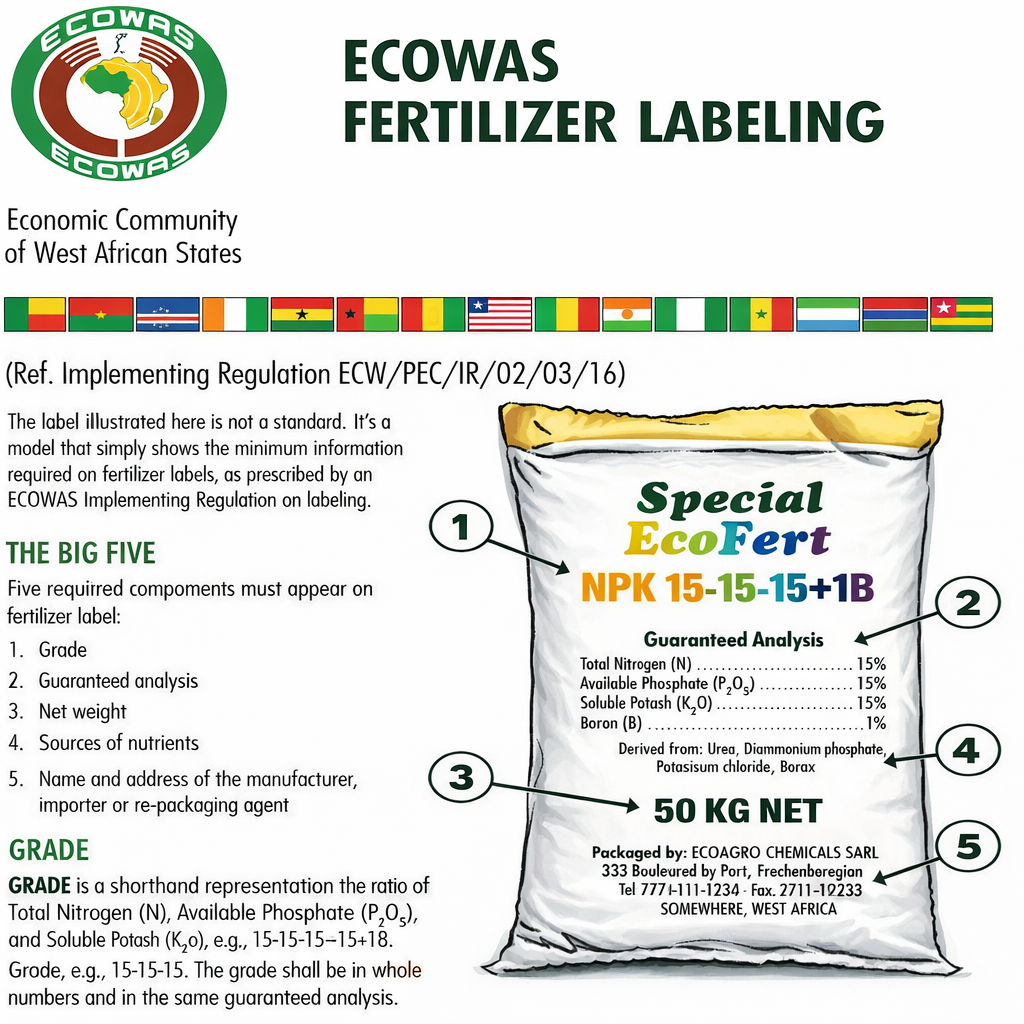
Mandatory Information The "Big Five" Must Be Included on the Label
Each fertilizer label must contain the minimum required information, commonly referred to as the “Big Five”:
- Fertilizer grade (e.g., NPK 15-15-15, expressed in whole numbers)
- Guaranteed nutrient analysis, including nutrient forms where applicable
- (Total N, Available P₂O₅, Soluble K₂O, and declared micronutrients)
- Net weight of the package
- Sources of nutrients
- Name and physical address of the manufacturer, importer, or re-packaging agent
Nutrient Values Must Match the Guaranteed Analysis
Declared nutrient contents must be accurate and verifiable. The fertilizer grade shown on the bag must exactly correspond to the guaranteed analysis, including nutrient order, units, and percentages, as defined by ECOWAS standards.
Product Identification and Traceability
Labels must allow traceability of the product. This typically includes:
- Product or brand name
- Batch or lot number (recommended for enforcement and recall purposes)
- Manufacturing or packaging identification
Prohibition of Misleading Claims
Labels must not contain false, exaggerated, or unsubstantiated claims regarding fertilizer performance, yield improvement, or soil enhancement. All statements must be technically and scientifically defensible.
Label Information Must Match the Packaged Product
The fertilizer inside the bag must fully correspond to the labeled formulation. Re-labeling or re-packing without authorization, or using labels inconsistent with actual nutrient content, is strictly prohibited.
Disposal of (used) bags
Used fertilizer blending packaging bags must be handled and disposed of in a controlled and environmentally responsible manner to prevent contamination and misuse. After emptying, bags should be collected, bundled, and disposed of at an approved landfill or waste management facility in accordance with local environmental regulations. Open dumping or uncontrolled burning of used bags is not permitted, as residual fertilizer may pose environmental and safety risks.
Where recycling facilities are available, used bags may be recycled into non-food, non-agricultural applications, such as filling or padding materials for handmade furniture or other industrial reuse where there is no risk of contact with food, crops, or animal feed. Any recycling process must ensure that the bags are not reintroduced into the agricultural supply chain.
Warning: Used fertilizer packaging bags are strictly prohibited from being reused to store or transport agricultural products, including crops such as cocoa. Residual fertilizer nutrients and chemical contaminants can pose serious risks to food safety and export compliance.
- Bundle and dispose of used bags in an approved landfill.
- Bags can be recycled into nonuseable items, such as filling or
- padding for handmade furniture.
- WARNING: Used fertilizer bags are prohibited to be used to store or transport crops, including cocoa.
What is the process flow of a BB fertilizer production line?
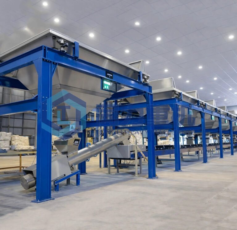
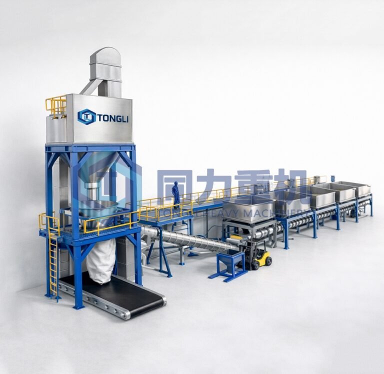
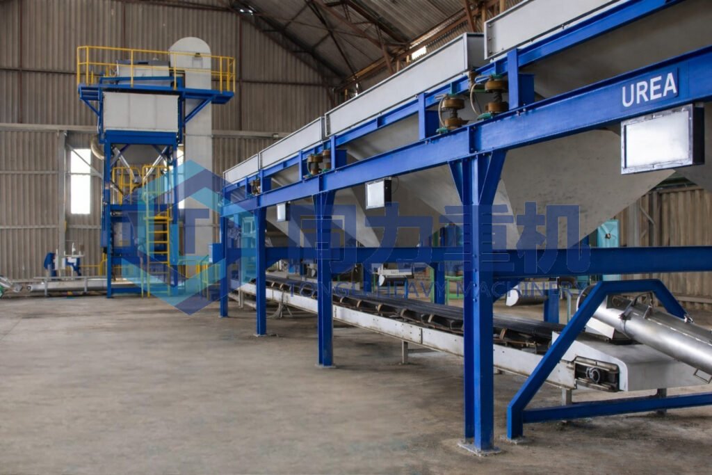
In a BB fertilizer blending line designed for declining-weight (loss-in-weight) blending, the process starts by accurately inputting the fertilizer formulation into the PLC-based control system, which governs the entire bulk blending operation. Raw materials are charged into individual feed hoppers and lifted by a charging elevator to the feed bin, where level sensors ensure stable material supply. The feed bin dynamically discharges material to the loss-in-weight flow controllers, which perform continuous, real-time gravimetric dosing according to the preset recipe, ensuring high-precision fertilizer proportioning. The metered materials are then evenly and stratifiedly distributed by a pre-mix conveyor, achieving initial homogenization before entering the blender. Inside the BB fertilizer mixer, the materials are thoroughly blended and conveyed to the main bucket elevator, which transfers the finished blend to the product storage bin for buffering prior to packing. Finally, a fertilizer bagging system equipped with a quantitative packing scale weighs the blended fertilizer to the set bag weight, after which the bags are conveyed, stitched by an automatic sewing machine, oriented and stacked at a defined height, ready for truck loading—completing a fully automated, continuous bulk blending fertilizer production line with high accuracy, flexibility, and throughput.
Conclusion:
Operating a bulk blending fertilizer plant efficiently and safely requires far more than simply combining raw materials. It needs a systematic, well-controlled operational framework that integrates correct operating procedures, trained personnel, compliant packaging, and robust quality control. In this article, we have detailed the complete operational logic of a bulk blending fertilizer plant—from day-to-day operating practices and standard operating procedures (SOPs) for each job role, to common operational mistakes, practical troubleshooting methods, and preventive measures. We have also addressed the often-overlooked but critical downstream elements, including proper selection of packaging bags. When these operational, technical, and compliance aspects are managed as an integrated system, a bulk blending fertilizer plant can achieve stable production, consistent nutrient accuracy, reduced material loss, and improved safety performance, after read this article if you are interested in investing in such automated fertilizer blending system please check out our previous article: "What to Consider When Building & Investing a Fertilizer Bulk Blending Plant? A Practical Guide" For Quotations of such line please don't hesitate to contact us!