


KL2 bevel-planetary mill gearboxes general data and requirements
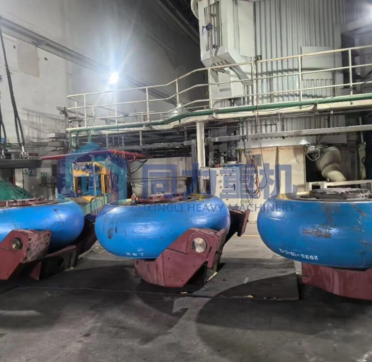
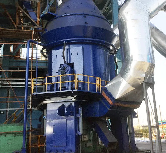
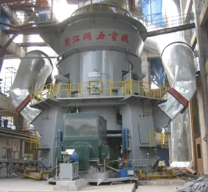
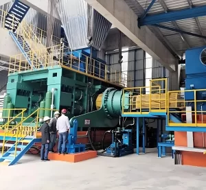
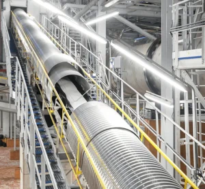
KL2 bevel-planetary mill gearboxes are manufactured in 10 sizes. Their maximum torque is 3000 kNm. They are supplied with a complete lubrication and cooling system, clutch, and monitoring system. They are used in loesche LM vertical roller mills in the cement, mineral resources, metallurgical, and other industries. Today we have a loesche vertical roller mill's moventas gearbox used in EuroChem-Karatau LLP that need repair, below is the general information of this KL2 bevel-planetary gearbox.
| No. | Description | Details |
| 1 | Type of repair | Major overhaul |
| 2 | Key technical and economic indicators | 2.1 Planned output capacity up to 0.9 million tons of phosphorite flour per year. 2.2 Planned start of repair – Q2 2026 |
| 3 | Location of gearbox | Zhambyl Region, Sarysu District, 18 km southwest of Zhanatas |
| 4 | Client | EuroChem-Karatau LLP |
| 5 | Source of financing | Client’s own funds |
Name and Application Scope
| No. | Parameter | Description |
| 6.1 | Position in process flow | Single-stage planetary gearbox with bevel gear, designed to drive the grinding table of ML24.2D mill (Loesche) |
| 6.2 | Drive shaft position | Horizontal |
| 6.3 | Output shaft position | Perpendicular to the drive shaft, oriented upward. Output element is a horizontal flange |
| 6.4 | Additional information | Gearbox is equipped with a segment-type thrust bearing in the upper housing, which absorbs all grinding forces |
| 6.5 | Gearbox design | Modular |
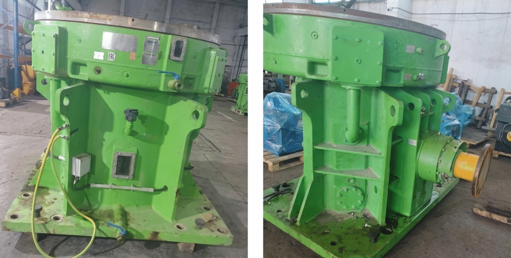
Technical Characteristics of Santasaló KL2 bevel-planetary Moventas Gears Oy (Finland)
| No. | Parameter | Value |
| 7.1 | Equipment type | Single-stage planetary gearbox with bevel gear, Type KL2-0320/300-SS27-AKS320-11 Protection class: IP64 |
| 7.2 | Installation conditions | Indoor installation, temperature range: 0°C to +47°C |
| 7.3 | Additional data | Technical characteristics must comply with Appendix No.1 and No.2 |
Main Technical Requirements
| No. | Parameter | Value |
| 8.1 | Service factor | 2.5 – 3.0 |
| 8.2 | Gear ratio (i) | 28.7 |
| 8.3 | Input shaft speed (rpm) | 990 |
| 8.4 | Output shaft speed (rpm) | 34.5 |
| 8.5 | Power (kW) | 600 |
| 8.6 | Torque (kNm) | 166 |
| 8.7 | Axial load (static, kN) | 1,750 |
| 8.8 | Axial load (dynamic, kN) | 5,550 |
| 8.9 | Lever arm radius at mill flange (mm) | 920 |
| 8.10 | Gearbox housing | Cast |
| 8.11 | Direction of rotation | Clockwise (motor side view) |
Requirements for Gear Transmission Mechanisms
| No. | Parameter | Requirement |
| 9.1 | Gear quality standard (DIN) | DIN 3961–3963, Accuracy grade 6 |
| 9.2 | Bevel gear stage | Hardened and primer-coated per HPG method. Teeth optimized for low noise. Gear quality per DIN 3961–3963 |
| 9.3 | Planetary stage | Involute gears, hardened and coated. Ring gear with improved hardening and tempering. Gear quality per DIN 3961–3963 |
| 9.4 | Bearing requirements | Self-aligning segmented bearings and hydrodynamic self-aligning segmented bearings. Service life ≥ 80,000 hours (ISO standard) |
| 9.5 | Load factor | KA = 2 |
| 9.6 | Safety factor (root) | SF > 1.6 |
| 9.7 | Safety factor (surface) | SH2 > 1.4 |
Price Table
| No. | Description of Service | Unit | Price (KZT, incl. VAT) |
| 1 | Major overhaul / refurbishment of Gearbox KL2 0320/300-SS27-AKS320-11, MFG No. W19939 (excluding lubrication system and coupling) | Service | |
| 2 | Logistics (both directions: Client–Contractor–Client) | Service |
Main Procurement Conditions (as per Tender Requirements)
| No. | Criteria | Client Requirement | Bidder’s Offer |
| 1 | Proposed works/services fully comply with SNiP, SN, SP, GOST, TU standards and specific requirements stated in the Technical Specification, as well as applicable regulatory requirements of the Republic of Kazakhstan | Acceptance | |
| 2 | Payment terms: Payment upon completion of works, with deferred payment of 30–90 calendar days from the date of service delivery | Acceptance | |
| 3 | We guarantee that the cost of on-site service is fixed and not subject to revision during the entire contract period | Acceptance | |
| 4 | We confirm availability of machinery, equipment, tools, and materials required to perform the works/services | To be provided | |
| 5 | We confirm availability of certified and qualified personnel with relevant experience | To be provided | |
| 6 | We guarantee that the completed works will be free from defects related to workmanship, manufacturing, design, or patent violations, and will meet performance requirements specified in the Technical Specification, ensuring safe and reliable operation | Acceptance | |
| 7 | Any defects identified by the Client shall be eliminated by the Contractor at its own expense | Acceptance |
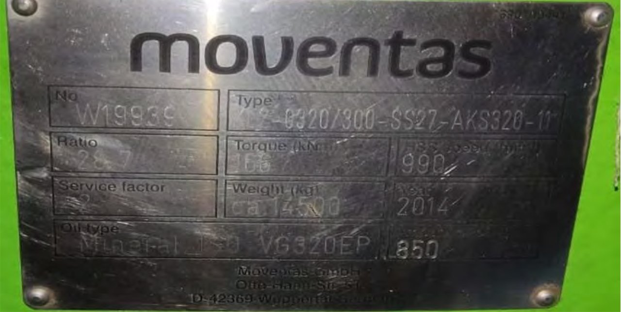
Moventas Gearbox Defects Report: Type KL2 0320/300 SS27-AKS320-11, s/n: W19939
The gearbox replacement program, by prior arrangement with the customer's representative, includes the following items:
- Complete gearbox disassembly with photographic documentation;
- Gear mesh inspection;
- Second-stage drive shaft inspection;
- Rolling bearing inspection;
- Plain bearing inspection;
- Satellite axle inspection;
- Planet carrier inspection;
- Rotary table inspection;
- Gearbox housing inspection;
- Pinion bevel shaft housing inspection;
- Second-stage drive shaft bearing housing inspection;
- List of required parts;
- Conclusion.
- Appendix to Report SR-055-25: Bearing Seat Measurement Protocol
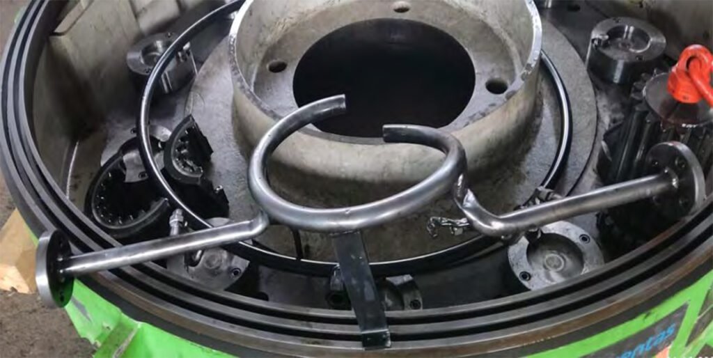
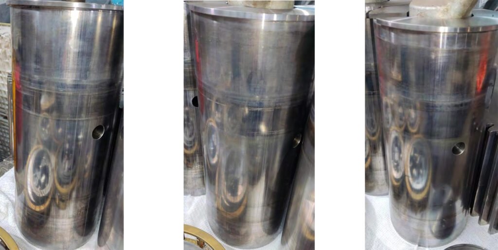
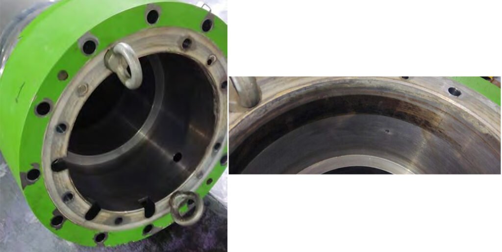
1. Complete gearbox disassembly with photographic documentation
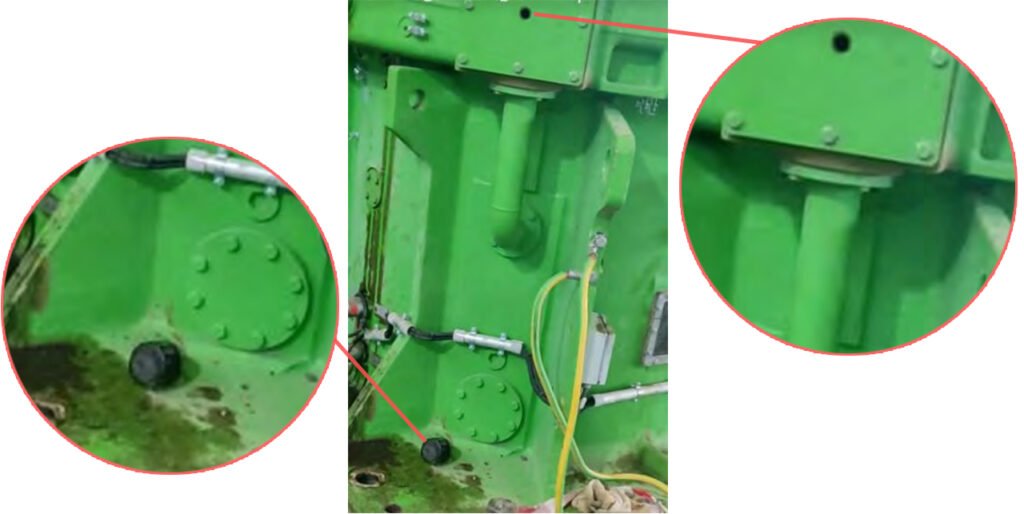
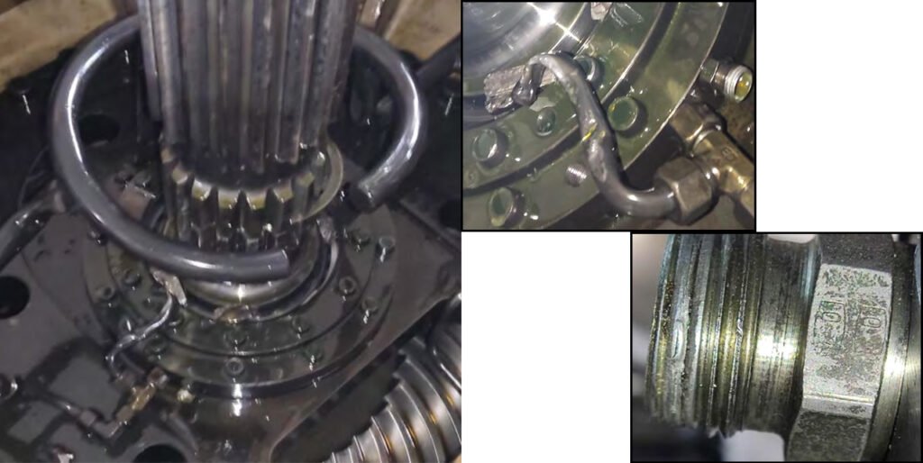
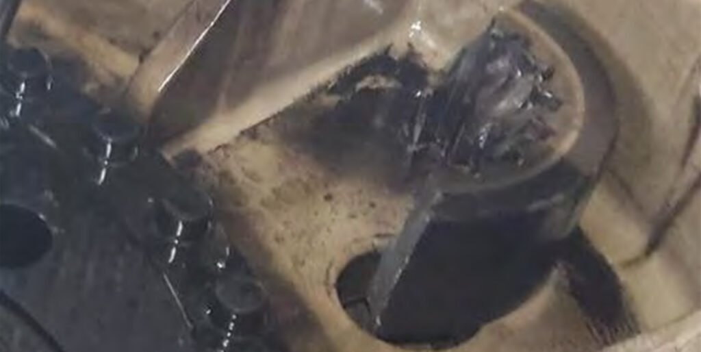
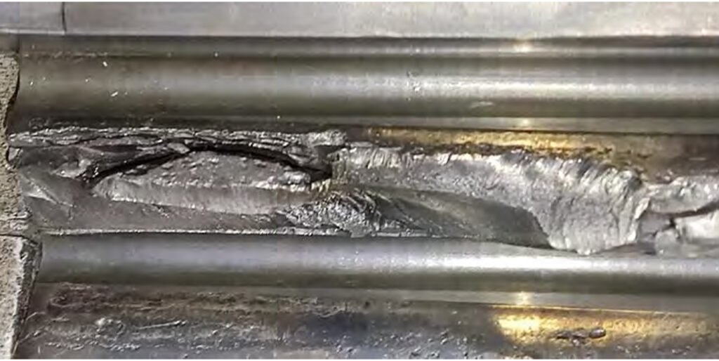
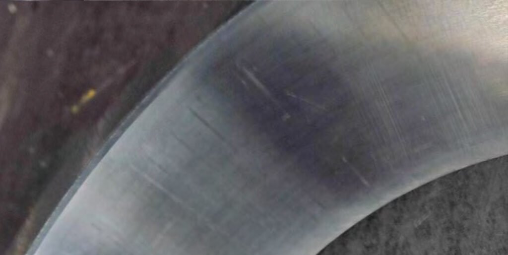
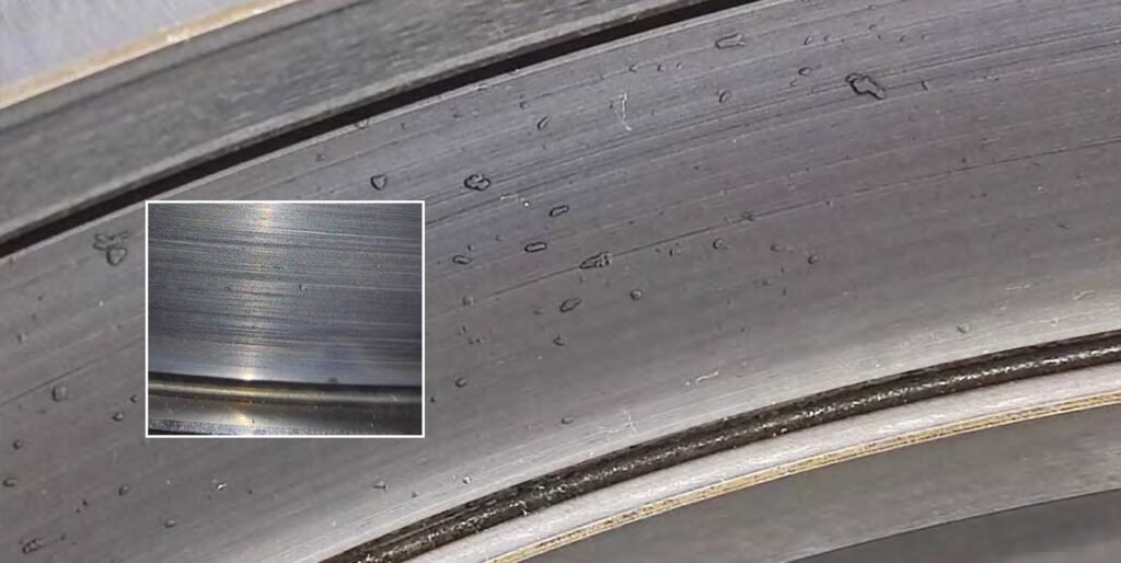
Complete disassembly of the gearbox with photo documentation. Upon acceptance of the gearbox, a broken breather valve from the plain bearing housing cover was discovered.
Conclusion: likely causes of the observed damage in a KL2 planetary gearbox
1. Overload and shock loading
Damage such as coupling failure, chipping of the second-stage drive shaft, and sun gear damage strongly indicates excessive torque or shock loads. In VRMs, this can be caused by unstable material feed, foreign objects entering the mill, or sudden load fluctuations during operation.
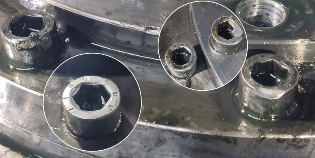
2. Misalignment and installation issues
Bent mounting bolts, burrs on splines, and damage to locking pins suggest misalignment between the gearbox, motor, and grinding table. Improper installation or foundation settlement can introduce uneven load distribution, leading to localized stress and premature wear.
3. Poor lubrication or lubrication failure
Damage to bearings, gears, and internal oil lines points to inadequate lubrication. This may result from oil contamination, insufficient oil flow, clogged lines, or failure of the lubrication system, leading to increased friction, overheating, and accelerated wear.

4. Assembly or maintenance deficiencies
Burrs on locking pins and splined inserts, as well as damaged fasteners (Allen screws), indicate improper assembly or previous maintenance errors. Incorrect torqueing, reuse of damaged parts, or poor handling during maintenance can introduce defects that worsen under load.
5. Fatigue and progressive wear
Cracks, chipping, and gear damage—especially on the sun gear and shafts—can develop over time due to cyclic loading. If early signs (like vibration or temperature rise) are not addressed, fatigue failure becomes inevitable.
6. Contamination and sealing issues
The broken breather valve suggests that contaminants (dust, moisture) may have entered the system. In cement and coal applications, contamination can rapidly degrade oil quality and accelerate internal wear.
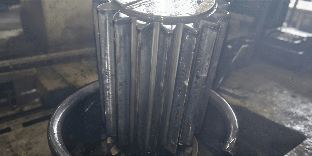
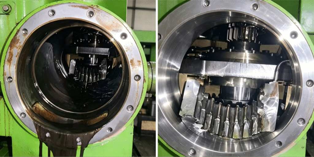
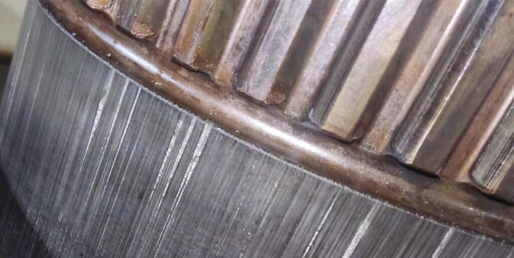
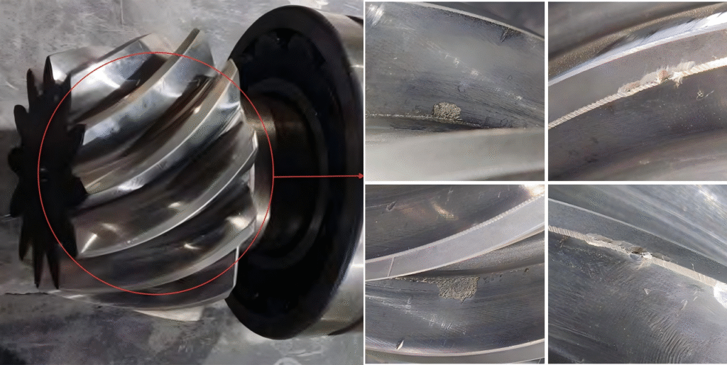
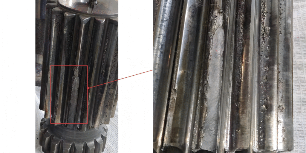
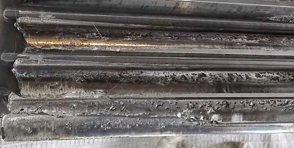
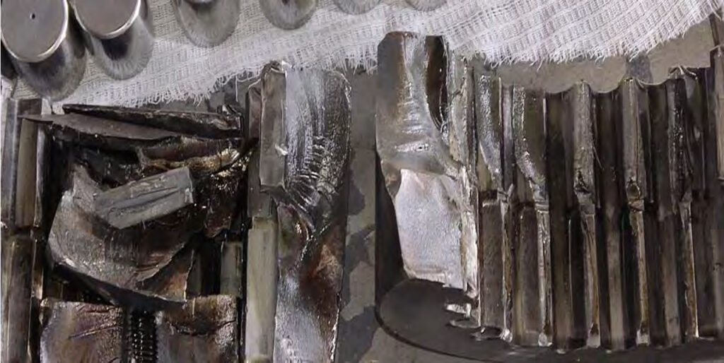
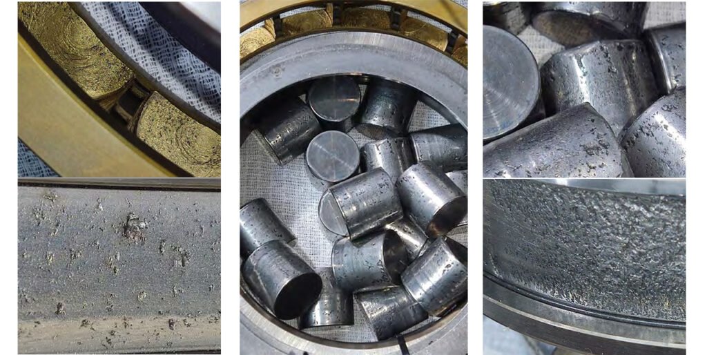
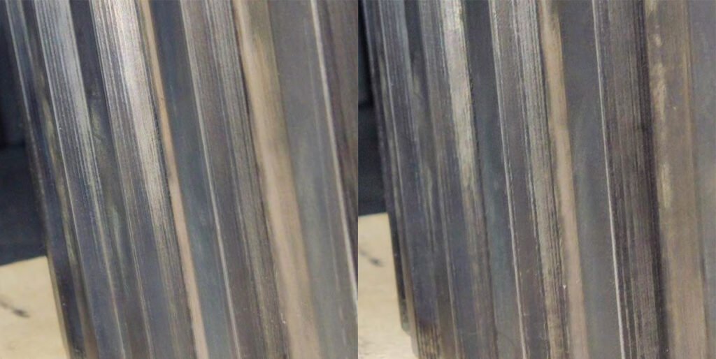
2. Gear mesh defect detection.
Damaged bevel gear keys.
Satellites.
1st satellite.
Tooth chips. Peeling of the tooth surface. Macropitting on the tooth surface. Numerous dents on the tooth surface.
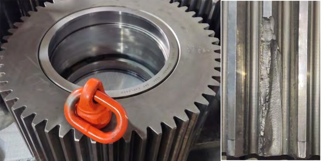
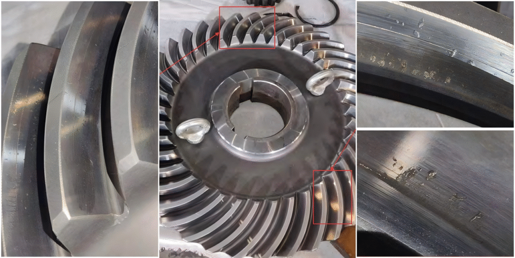
2nd satellite.
Chipping of the tooth surface. Macropitting on the tooth surface. Numerous dents on the tooth surface.
3rd satellite.
Chipping of the tooth surface. Macropitting on the tooth surface. Numerous dents on the tooth surface.
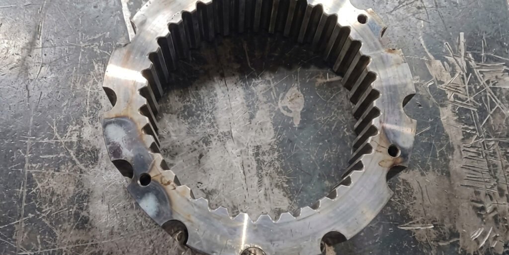
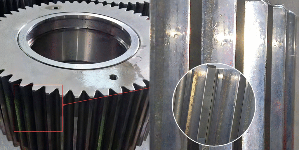
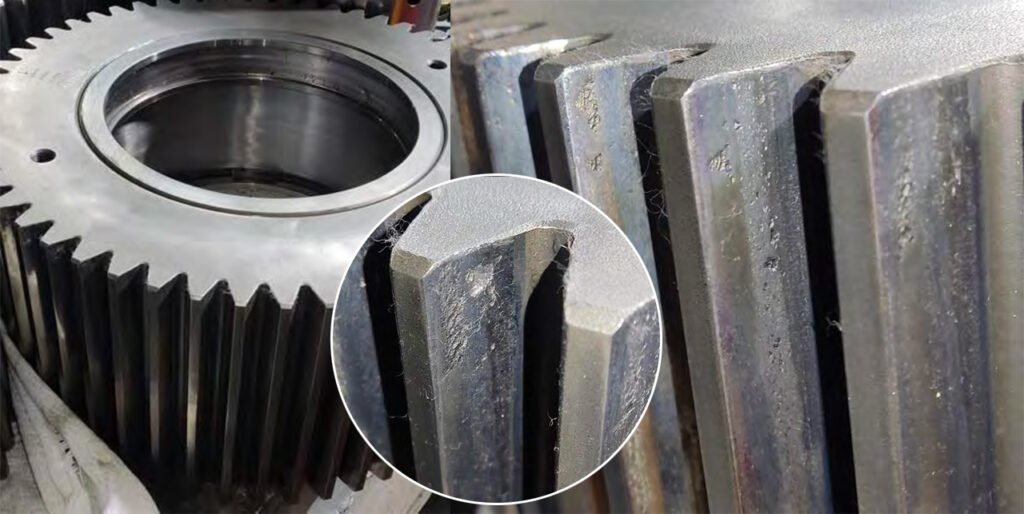
Crown gear
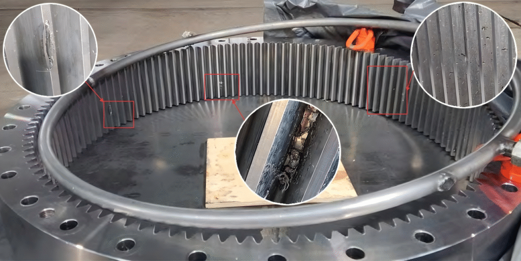
Cracked teeth. Chipping of the tooth surface. Numerous dents on the tooth surface.

What are the root causes of these specific KL2 planetary gearbox component damages?
1. Rolling Contact Fatigue (RCF) and Surface Failure
The widespread macropitting, tooth chipping, and surface peeling observed on the sun gear, satellites, and crown gear are typical of rolling contact fatigue. Under repeated cyclic loading, micro-cracks form beneath the hardened surface due to high contact stress and eventually propagate to the մակroscale, causing material to break away. This type of damage is often linked to material properties and long-term stress exposure rather than sudden overload.
- Inadequate case hardening depth or surface hardness
- Subsurface material defects or inclusions
- Prolonged operation near maximum design load
2. Abrasive Contamination and Indentation Damage
The numerous dents and indentations across gear tooth surfaces indicate the presence of hard particles circulating in the lubrication system. These contaminants (such as metal debris or process dust) create localized points when trapped between meshing gears, leading to surface indentation and accelerating fatigue failure. This is a specific case of contamination-driven wear rather than general lubrication failure.
- Entry of dust or debris through failed seals or breathers
- Poor oil filtration or maintenance practices
- Internal wear particles recirculating in the system
3. Fretting and Loss of Interference Fit

The looseness of the spherical roller bearing on the shaft, along with seat wear and corrosion, points to fretting damage caused by micro-movements between mating surfaces. Instead of a stable interference fit, cyclic loads and vibration cause slight relative motion, generating wear debris and oxidation, which further accelerates loosening.
- Improper fit tolerance or assembly method
- Thermal expansion mismatch during operation
- Continuous vibration leading to micro-slip
4. Contact Pattern Misalignment (Edge Loading)
Chipping on bevel gear teeth and damage near gear end faces suggest improper load distribution across the gear width, known as edge loading. This occurs when the contact pattern is not centered due to axial displacement, incorrect shimming, or structural deformation, causing stress to concentrate at the edges of the teeth.
- Incorrect spacer or shim adjustment
- Shaft axial displacement under load
- Housing or support structure deformation
5. Torsional Vibration and Dynamic Fatigue
The destruction of the coupling, retaining ring, and key components indicates the presence of torsional vibration or resonance in the drivetrain. Unlike simple overload, this involves cyclic torque oscillations that repeatedly stress components until fatigue failure occurs. This is common in VRMs where process instability can excite drivetrain dynamics.
- Resonance between motor, gearbox, and mill system
- Insufficient damping in the coupling design
- Fluctuating grinding loads from unstable material bed
6. Seal Interface Wear and Tribological Failure
Wear on the shaft sleeve at the seal contact area is caused by tribological issues at the sealing interface. Abrasive particles trapped at the seal lip, combined with friction and possible inadequate lubrication at the sealing surface, gradually wear down the shaft sleeve.
- Contaminants embedded in seal material
- Improper seal selection or installation
- Surface hardness mismatch between seal and sleeve
7. Structural Fatigue and Crack Initiation
Cracks in the crown gear teeth are typically initiated at high-stress such as the tooth root. These cracks can result from residual stresses introduced during manufacturing or from stress concentration under cyclic bending loads. Once initiated, cracks propagate under repeated loading, eventually leading to tooth failure.
- Residual stresses from heat treatment
- Tooth root geometry causing stress concentration
- Combined bending and contact fatigue over time
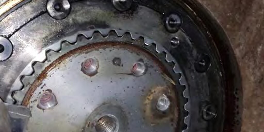
3. Defect detection of the second stage drive shaft.
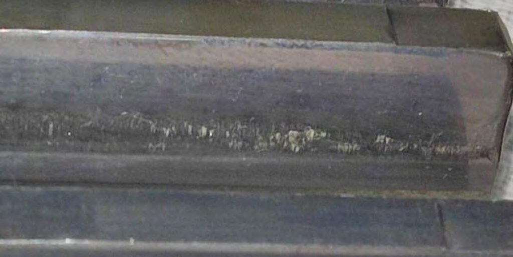
Chipping of shaft teeth.
Chips and cracks on the gear seat.
Damage to the shaft spacer bushings. Corrosion of the spacer bushings.
Fretting corrosion of the lower bearing seat
How does VRM operation cause damage to the second-stage drive shaft and its components?
1. Grinding Bed Instability and Torque Reversal Effects
The chipping of the second-stage shaft teeth is strongly linked to unstable grinding conditions inside the VRM. When the material bed becomes uneven or collapses (e.g., due to fluctuating feed rate or improper dam ring height), the mill experiences sudden torque reversals and impact loads. These dynamic shocks are transmitted directly through the drivetrain, causing localized overload on shaft teeth and initiating chipping at high-stress.
- Frequent mill vibration or “rumbling” operation
- Inconsistent material feed or particle size distribution
- Sudden changes in grinding pressure
2. Axial Thrust Fluctuation from Grinding Force Variation
Cracks and chips on the gear seat, as well as damage to spacer bushings, are closely related to unstable axial forces generated during VRM operation. The grinding rollers exert varying on the table, which translates into fluctuating axial loads on the gearbox shaft. Over time, this causes cyclic stress at the gear mounting interface and spacers, leading to fatigue cracking and mechanical degradation.
- Variations in hydraulic grinding pressure
- Uneven roller loading or wear
- Mill startup and shutdown cycles inducing thrust variation
3. Thermal Cycling from Process Temperature Variations
Corrosion and degradation of spacer bushings can be driven by temperature fluctuations inherent in VRM operation, especially in cement and coal grinding. Hot gas flow used for drying introduces thermal cycling, which leads to condensation during shutdowns. This moisture promotes corrosion on exposed components like spacer bushings.
- Frequent hot/cold cycling during operation and stoppage
- Ingress of humid air during idle periods
- Inadequate heating or insulation of gearbox
4. Low-Speed High-Torque Operation and Micro-Slip at Fits
Fretting corrosion at the lower bearing seat is a direct consequence of the VRM’s operating profile: low speed combined with very high torque. Under these conditions, the shaft does not rotate fast enough to maintain a fully stable fit, and small elastic deformations occur under load. This leads to micro-slip between the bearing and shaft seat, initiating fretting corrosion over time.
- Continuous operation at high torque but low rotational speed
- Load pulsations from grinding process
- Insufficient interference fit for such duty conditions
5. Dynamic Load Transmission Through the Grinding Table
Damage to spacer bushings and gear seat areas is also influenced by how grinding forces are transmitted from the table into the gearbox. In VRMs, the gearbox not only transmits torque but also supports part of the grinding load. Any instability in the grinding zone (e.g., uneven material layer) results in non-uniform load transfer, causing localized overstressing of shaft-mounted components.
- Uneven material distribution on grinding table
- Table runout or wear affecting load symmetry
- Interaction between gearbox and mill structure
6. Start-Stop Cycles and Transient Load Peaks
Repeated start-ups and shutdowns of the VRM introduce transient torque and axial load peaks that are much higher than steady-state conditions. These transient events are particularly damaging to shaft interfaces such as gear seats and spacers, where stress concentration is already high. Over time, this leads to crack initiation and progressive failure.
- Frequent operational interruptions
- Improper startup procedures (e.g., loaded starts)
- Emergency stops under load
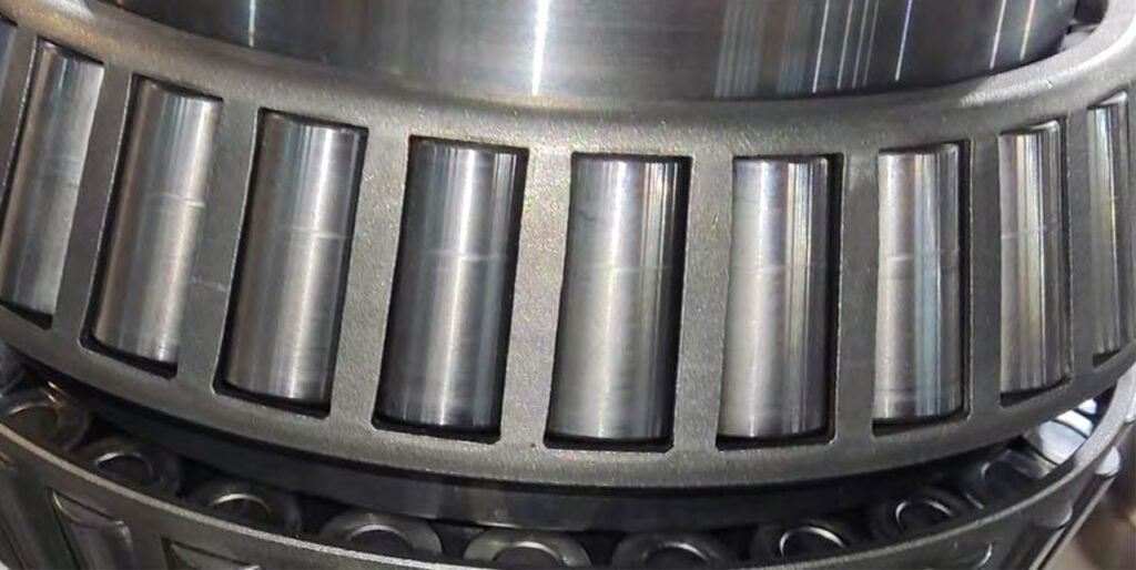
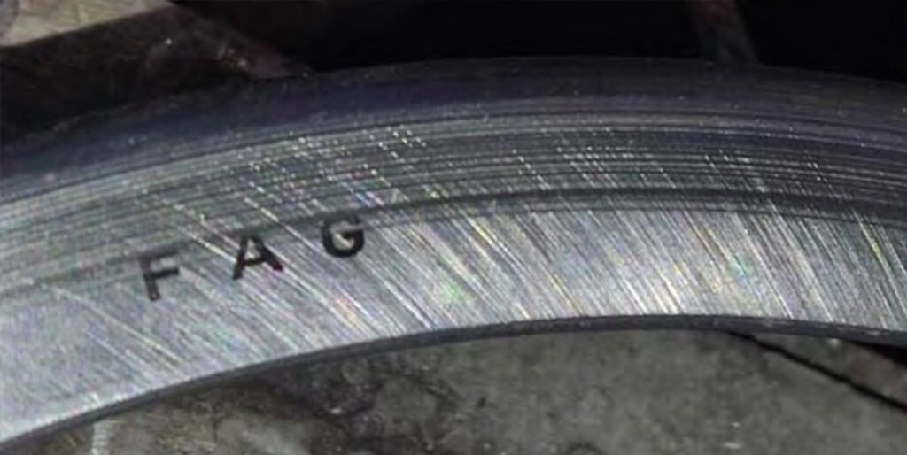
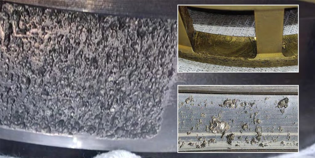
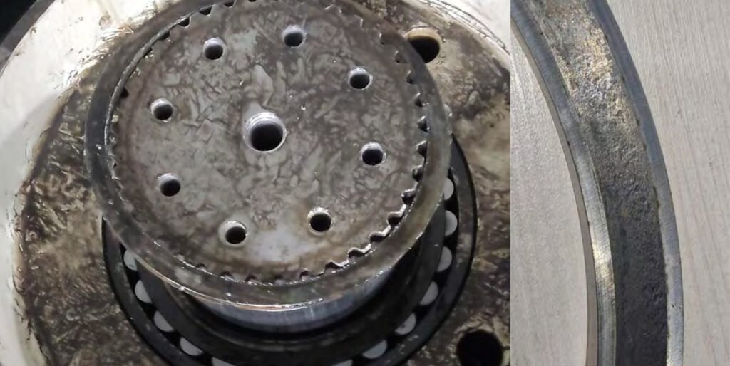
4. Defect detection of rolling bearings.
Frontal tapered roller bearing of the tapered pinion shaft
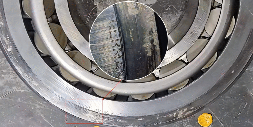
Marks on the outer race from excessive axial pressure on the bevel shaft housing cover. Chipping of the roller and outer race surfaces. Numerous dents on the roller and race surfaces.
Main tapered roller bearing of the tapered pinion shaft.
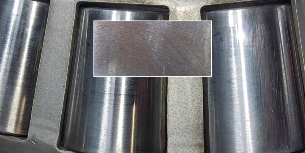
Peeling of roller and outer race surfaces. Brinelling. Dents on roller and outer race surfaces.
Spherical roller bearing of tapered pinion shaft
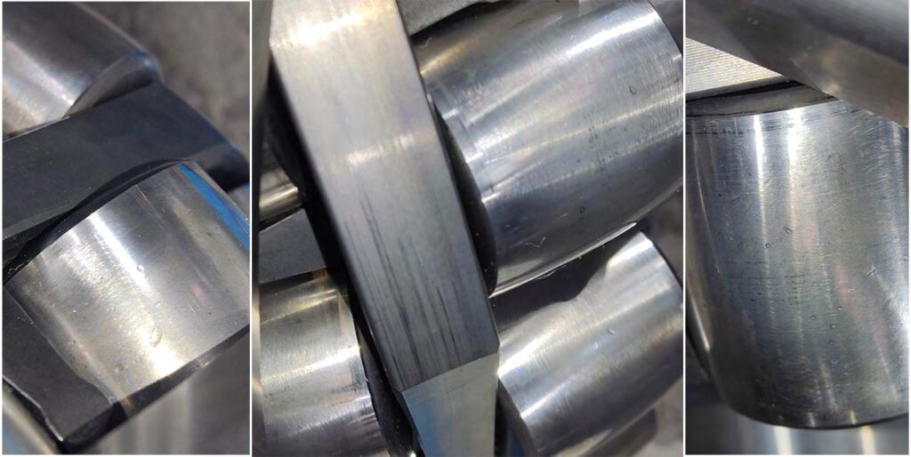
Peeling of roller and outer race surfaces. Numerous dents on the roller and outer race surfaces.

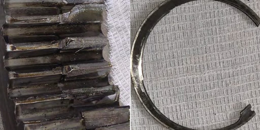
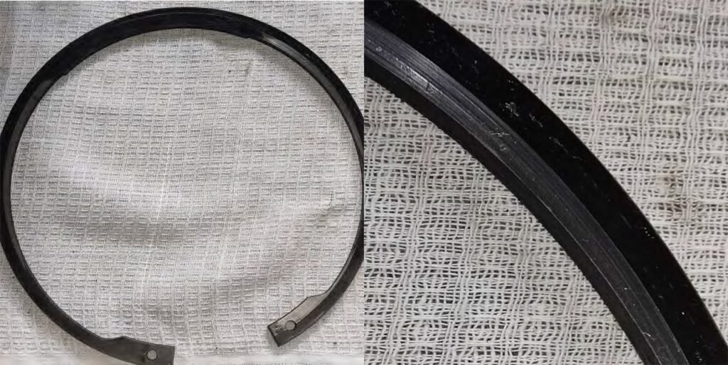
Lower, cylindrical roller bearing of the second stage drive shaft.
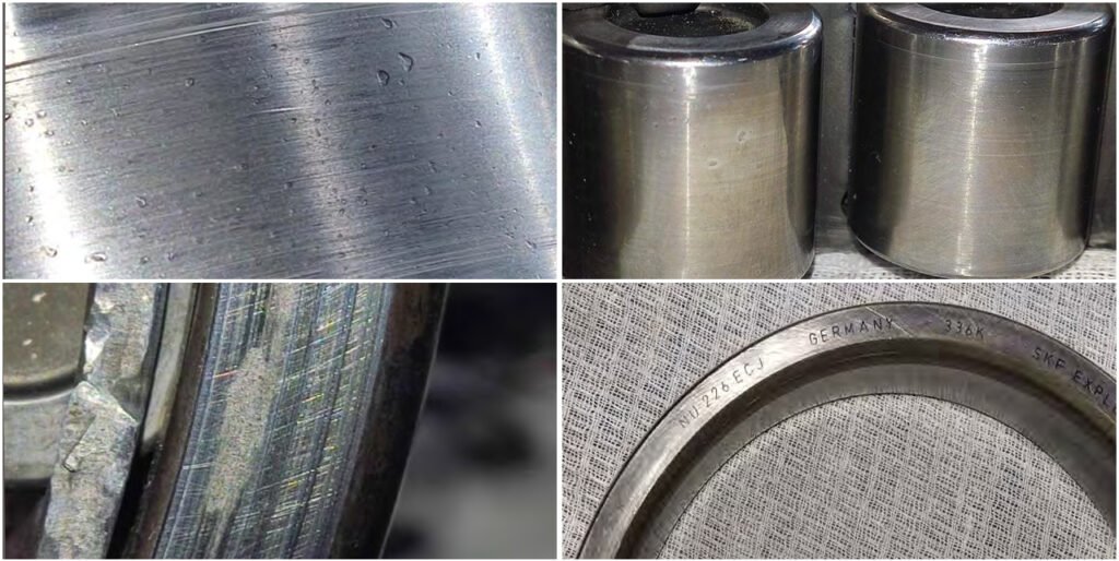
Peeling of the roller and inner race surfaces. Numerous dents on the roller and race surfaces. Traces of the bearing rotating in the housing. Traces of the outer race sticking in the housing. Retaining ring wear due to bearing rotation in the housing.
Lower tapered roller bearing of the second stage drive shaft.
Peeling of the roller and outer race surfaces. Numerous dents on the roller and outer race surfaces. Brinelling. Traces of bearing rotation in the housing.
Upper tapered roller bearing of the second stage drive shaft.
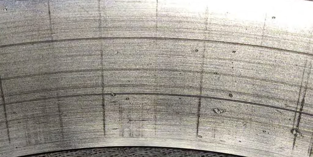
Peeling of roller and outer race surfaces. Numerous dents on roller and race surfaces. Brinelling. Traces of bearing rotation in the housing.
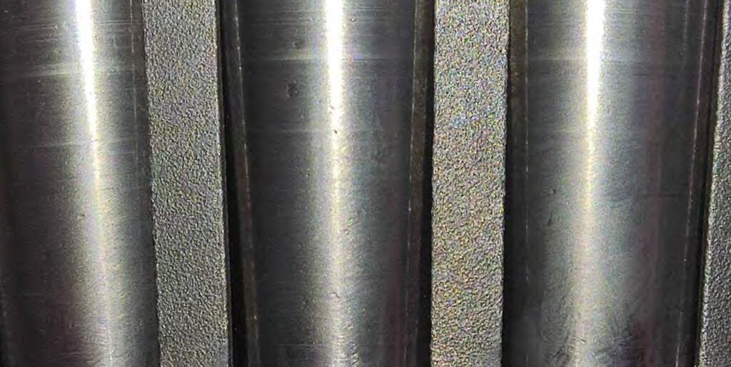
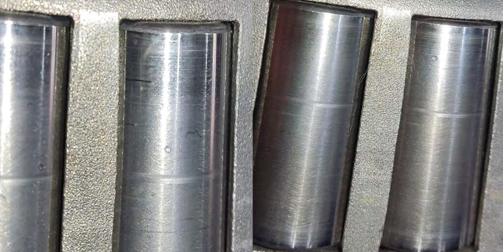
Planet gear bearings.
1st planet gear bearings.
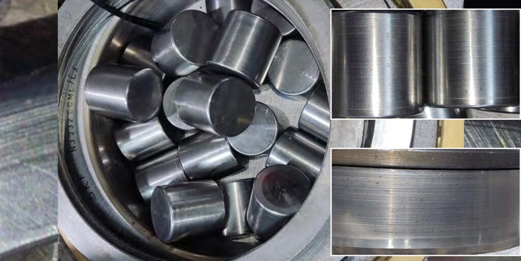
Peeling of roller surfaces, inner and outer races. Numerous dents on roller and race surfaces.
Bearings of the 2nd satellite.
Peeling of roller surfaces, inner and outer races. Numerous dents on roller and race surfaces. Damage to separators.
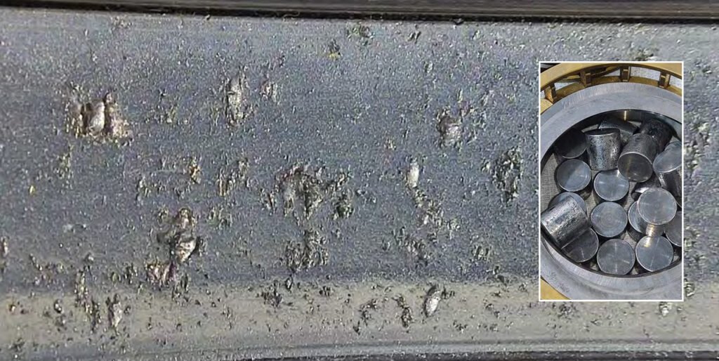
Peeling of roller surfaces, inner and outer races. Numerous dents on roller and race surfaces. Damage to separators.
Carrier roller bearing.
Painting of the surfaces of rollers, inner and outer races.
VRM-Induced Bearing System Instability
1. Hydraulic Grinding Force Overload and Axial Bearing Stress
The marks on the outer race of the frontal tapered roller bearing, along with chipping and dents, indicate excessive axial loading transmitted from the VRM grinding process. In operation, the hydraulic system applies grinding force through the rollers onto the table, which is partially transferred into the gearbox via the bevel shaft. If grinding pressure is set too high or fluctuates excessively, it can overload axial bearings, causing race deformation, surface damage, and eventual material chipping.
- Excessive or unstable hydraulic grinding pressure
- Improper control of grinding force during operation
- Uneven load transfer from grinding table
2. Material Bed Collapse and Impact Loading (Brinelling Formation)
Brinelling observed in multiple tapered roller bearings is typically caused by shock loads rather than continuous operation stress. In a VRM, this occurs when the material bed collapses or when the mill runs with insufficient material, leading to direct metal-to-metal contact between rollers and table. These impact loads are transmitted through the drivetrain and create permanent indentations on bearing raceways.
- Empty or low-load mill operation
- Sudden material bed collapse
- High vibration events during unstable grinding
3. High-Frequency Vibration and Surface Fatigue in Bearings
Peeling (spalling) across roller and race surfaces in multiple bearings is a result of high-frequency vibration generated during VRM operation. Unlike standard fatigue, VRMs often operate under fluctuating loads and vibration بسبب process instability, which accelerates subsurface crack formation in bearing, leading to surface material detachment.
- Continuous mill vibration due to poor grinding conditions
- Imbalance in grinding rollers or table
- Resonance within the mill-gearbox system
4. Contaminant Ingress from Process Environment
The numerous dents across rollers and raceways in nearly all bearings strongly indicate contamination from the VRM process environment. Fine particles such as cement dust, coal dust, or metal debris can enter the lubrication system and become embedded between rolling elements, causing indentation damage and accelerating wear.
- Ineffective sealing against process dust
- Breather system allowing contaminated air ingress
- Poor oil cleanliness control under harsh plant conditions
5. Bearing Housing Deformation Under Grinding Load
Traces of bearing rotation in the housing, sticking of outer races, and retaining ring wear suggest deformation of the bearing housing under operational load. In VRMs, the gearbox is subjected not only to torque but also to grinding forces transferred from the mill. These forces can slightly distort the housing, reducing bearing seat integrity and allowing the bearing to move or rotate.
- Structural deformation due to grinding forces
- Inadequate housing stiffness for operating conditions
- Uneven foundation or load transfer
6. Thermal Expansion Mismatch and Fit Loss
Bearing rotation in the housing and wear of retaining components can also be driven by thermal effects during VRM operation. The combination of hot gas flow (for drying) and mechanical heat generation causes temperature gradients within the gearbox, leading to differential expansion between shafts, bearings, and housing. This can reduce interference fits and promote movement at bearing interfaces.
- High process temperatures from hot gas
- Uneven cooling or lubrication temperature control
- Repeated thermal cycling during operation
7. Lubrication Film Breakdown Under Extreme Load Zones
Peeling and separator damage in planet gear bearings indicate localized lubrication film failure. In VRMs, the combination of high load and low rotational speed makes it difficult to maintain a full hydrodynamic oil film, especially in heavily loaded zones like planetary bearings. This leads to metal-to-metal contact, overheating, and accelerated surface fatigue.
- Low-speed, high-load operating regime
- Insufficient oil film thickness in planetary stage
- Inadequate lubrication flow distribution
7. Cage (Separator) Fatigue from Load Fluctuation
Damage to bearing separators (cages) in planetary bearings is typically caused by uneven load distribution and dynamic forces within the gear system. In VRM operation, fluctuating torque and load sharing between planet gears can create irregular forces on rolling elements, which are transferred to the cage, leading to fatigue and eventual failure.
- Uneven load sharing among planet gears
- Dynamic torque fluctuations أثناء grinding
- Misbalance in planetary gear system
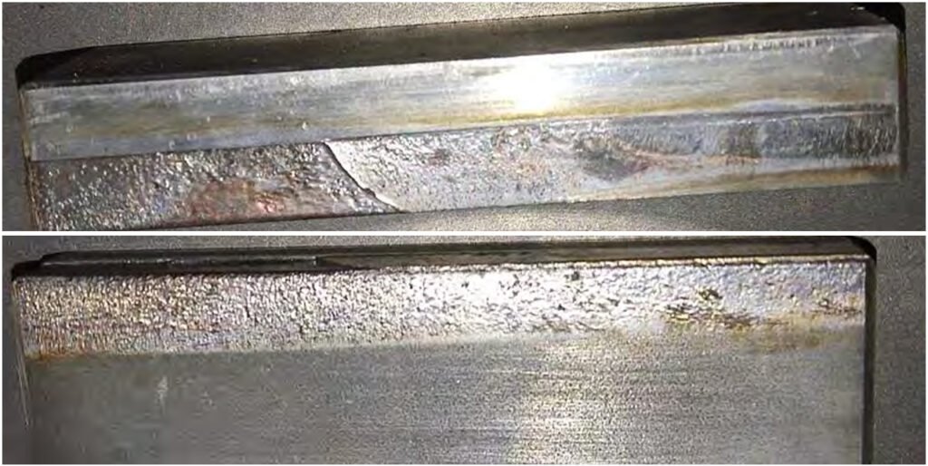
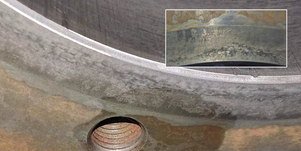
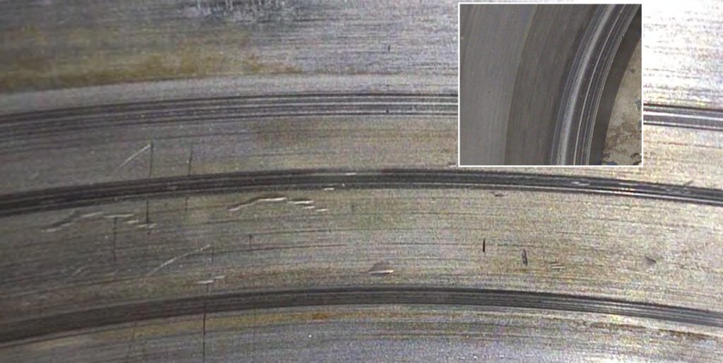
5. Defect detection of plain bearings.
There are signs of normal wear. No defects were found.
6. Defect detection of satellite axles.
No defects were found
7. Driver defect detection.
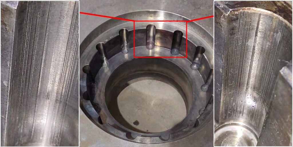
Fretting corrosion of the satellite axle seats.
Scuffs on the drive shaft.
No defects in the carrier shaft splines were found.
Wear of the carrier spacer ring due to excessive pressure from the turntable.
8. Rotary table defect detection.
There are signs of moderate wear. No scoring or damage was found on the bearing surfaces.

Scoring on the contact surface of the carrier shaft. Wear of the contact area with the carrier spacer ring due to measured pressure. Corrosion.
FAQ: How does VRM operation cause fretting, scuffing, and carrier component wear in the gearbox drive system?
1. Cyclic Load Transfer and Micro-Movement at Planet Axle Seats
Fretting corrosion at the satellite (planet) axle seats is primarily caused by cyclic load transfer inherent in VRM operation. As grinding forces fluctuate with changes in the material bed and roller pressure, the load shared by each planet gear is never perfectly constant. This results in micro-movements at the axle-seat interface, even under tight fits, generating fine wear particles and oxidation typical of fretting corrosion.
- Uneven load sharing between planet gears during grinding
- Continuous fluctuation of grinding forces
- High torque with low rotational speed promoting micro-slip
2. Sliding Contact and Boundary Lubrication on Drive Shaft Surfaces
Scuffing on the drive shaft indicates localized breakdown of the lubrication film, leading to direct metal-to-metal contact. In VRM applications, this is often linked to boundary lubrication conditions caused by high loads and relatively low speeds, where a full oil film cannot always be maintained. Transient conditions such as startup, shutdown, or sudden load changes further aggravate this, causing surface scoring and material transfer.
- Boundary or mixed lubrication regime under high load
- Insufficient oil film during transient operation
- Local overheating at contact
3. Grinding Force Transmission and Axial Overloading of Carrier Components
Wear of the carrier spacer ring due to excessive pressure from the turntable reflects how grinding forces are transmitted through the VRM into the gearbox structure. The gearbox not only transmits torque but also absorbs part of the vertical grinding load. When grinding pressure is high or unevenly distributed, excessive axial force is transferred to the carrier assembly, overstressing components like spacer rings and leading to wear or deformation over time.
- Excessive hydraulic grinding pressure
- Uneven material bed causing non-uniform load transfer
- Direct force path from turntable into gearbox carrier system
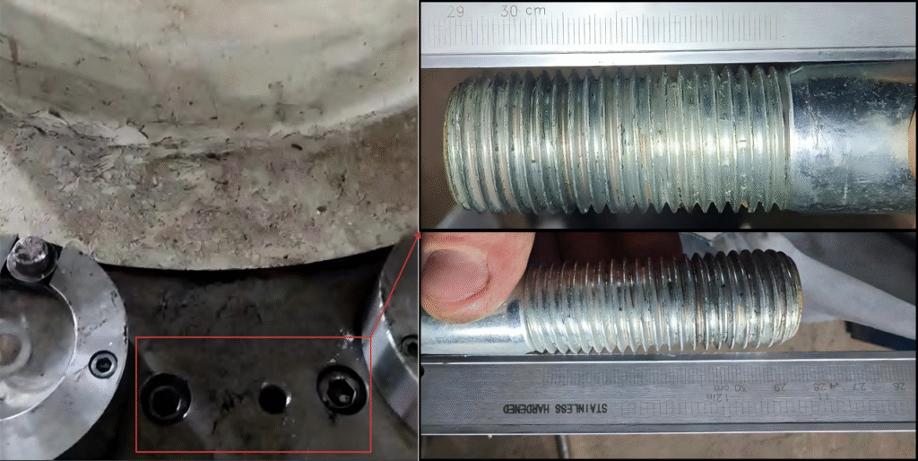
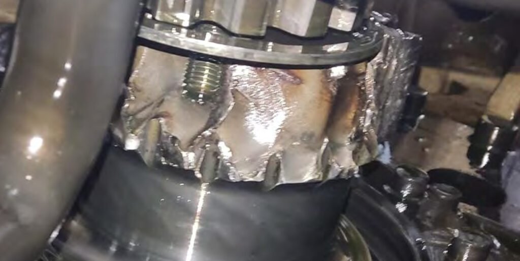
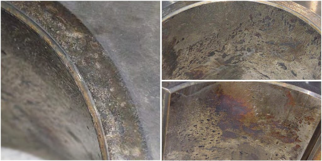
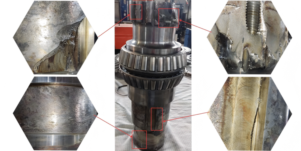
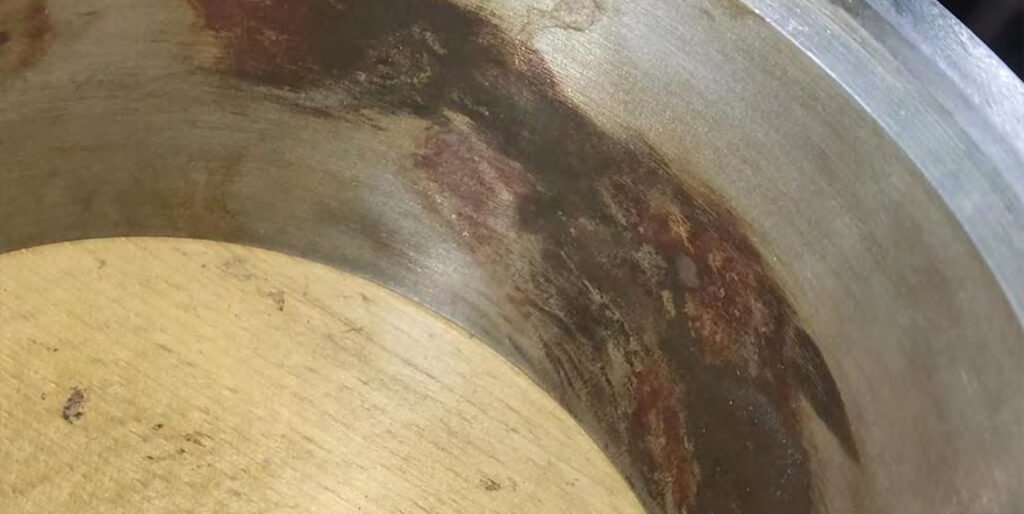
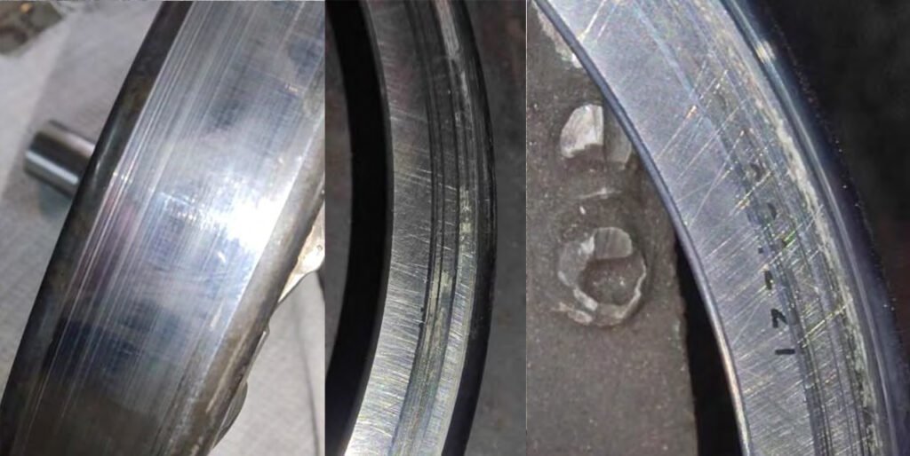
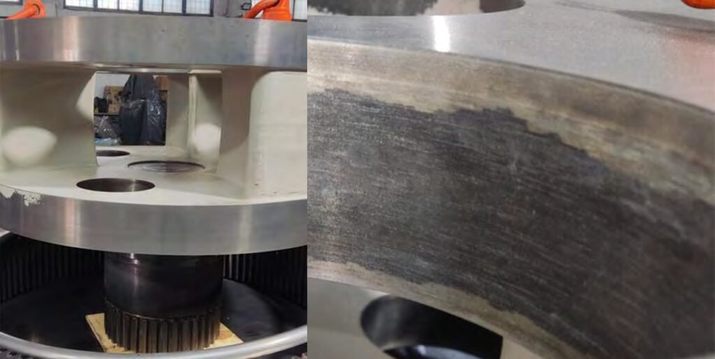
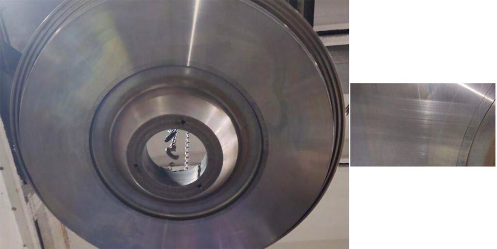
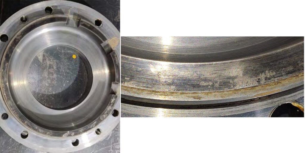
9. Defective body.
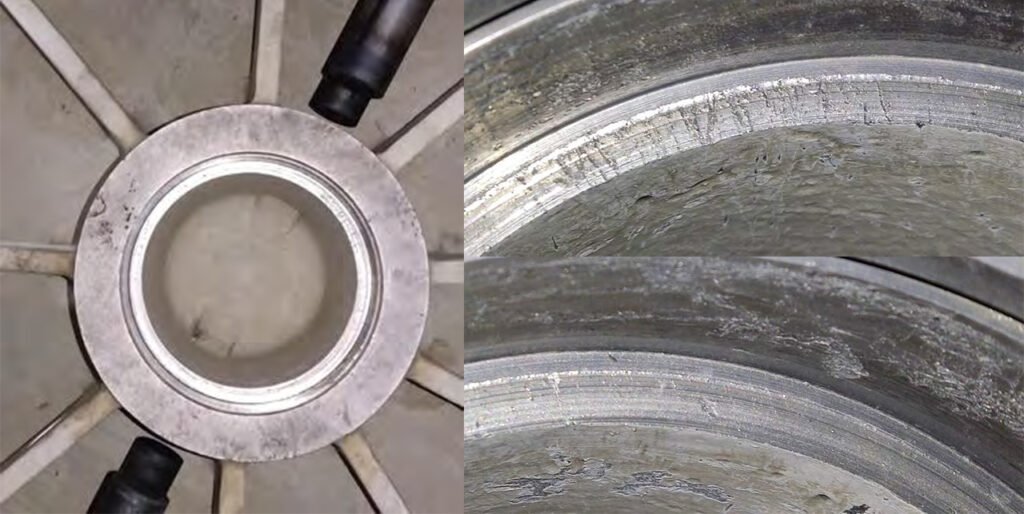
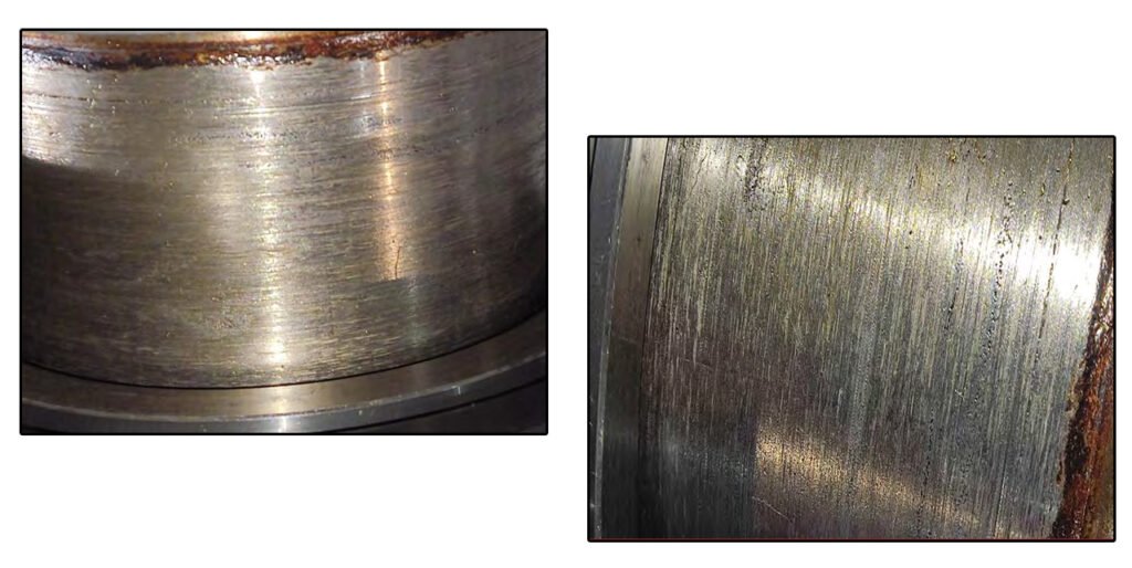
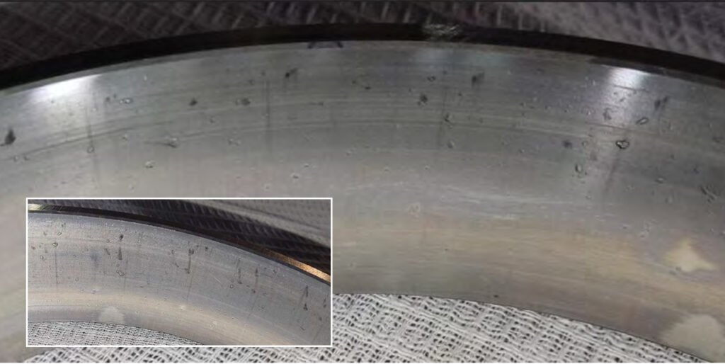
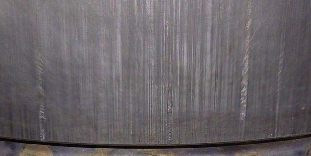
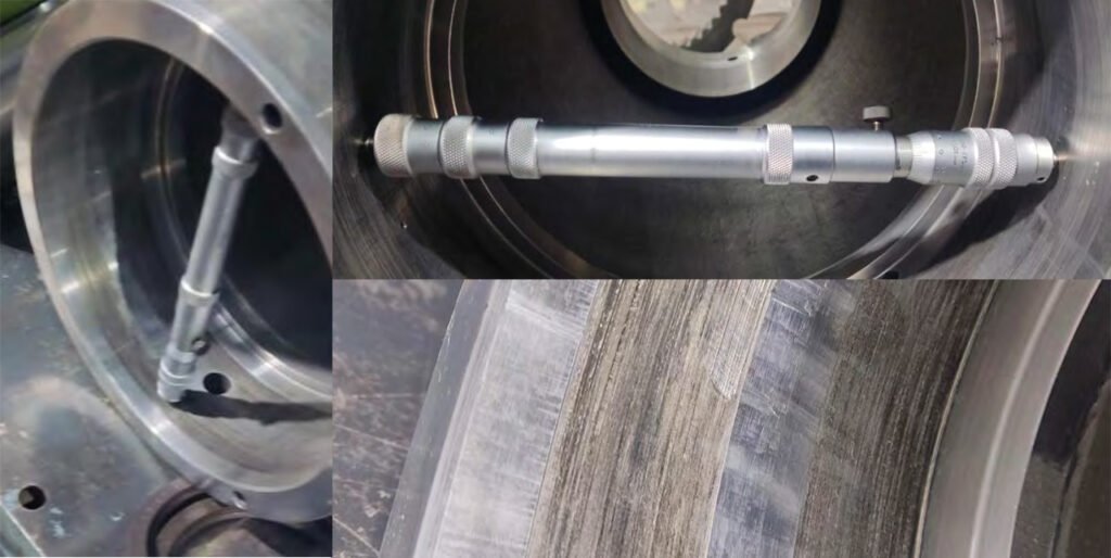
Wear of the lower cylindrical roller bearing seat on the second-stage drive shaft. The measurement results are presented in the appendix to the report "Appendix to Report SR-055-25: Bearing Seat Inspection Protocol in the Housing."
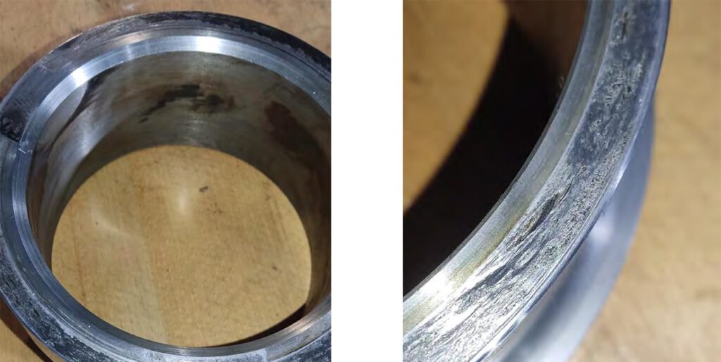
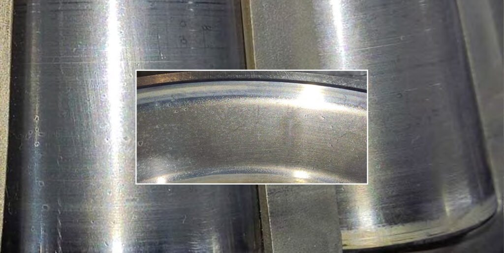
10. Defective housing of the bevel gear shaft.
Wear of the spherical roller bearing seat. Measurement results are presented in the appendix to the report "Appendix to Report SR-055-25: Bearing Seat Inspection Protocol in the Housing."
Corrosion and fretting corrosion of tapered roller bearing seats.
Wear of the cover thrust flange due to increased axial pressure of the outer bearing race.
What causes bearing seat wear, fretting corrosion, and thrust flange damage in VRM gearbox housings?
1. Grinding Force Transmission and Housing Seat Deformation
Wear of the spherical roller bearing seat in the housing is primarily driven by how grinding forces are transmitted through the VRM into the gearbox structure. Unlike conventional gearboxes, VRM gearboxes absorb part of the vertical grinding load, which can cause localized deformation of the housing under sustained operation. This deformation reduces the integrity of the bearing seat, leading to gradual wear and loss of proper fit.
- Continuous transfer of grinding forces into gearbox housing
- High structural load beyond pure torque transmission
- Long-term elastic deformation under heavy duty operation
2. Micro-Vibration and Environmental Exposure at Bearing Seats
Corrosion and fretting corrosion on tapered roller bearing seats result from a combination of VRM-induced vibration and exposure to a harsh process environment. Small oscillatory movements at the bearing-housing interface, combined with moisture ingress (often during shutdown cycles), promote oxidation and fretting damage. This is especially common in applications involving hot gas and dusty conditions.
- Vibration-induced micro-movement at bearing interfaces
- Moisture ingress during thermal cycling and periods
- Contaminated atmosphere from cement/coal grinding
3. Axial Load Concentration from Grinding Pressure Imbalance
Wear of the cover thrust flange is directly related to excessive axial pressure exerted by the bearing outer race, which is influenced by VRM grinding conditions. When grinding pressure is too high or unevenly distributed, axial loads increase significantly and are transferred to the bearing and housing components. This leads to concentrated stress at the thrust flange, causing accelerated wear over time.
- Excessive or poorly controlled grinding pressure
- Uneven load distribution across grinding table
- Axial force accumulation within gearbox structure
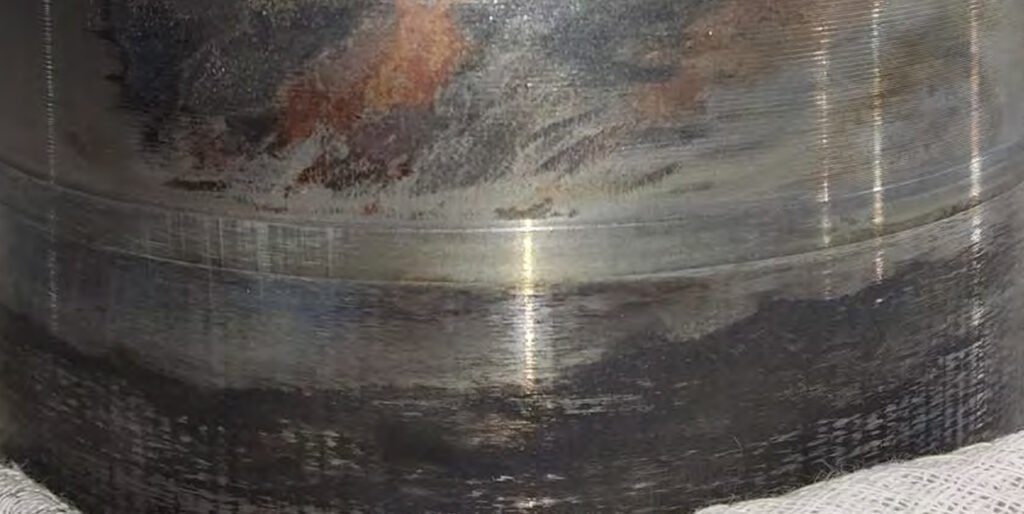
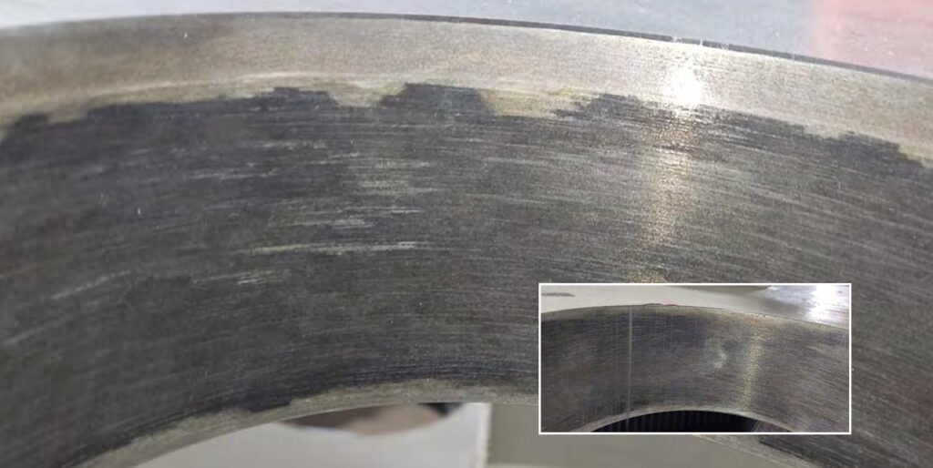
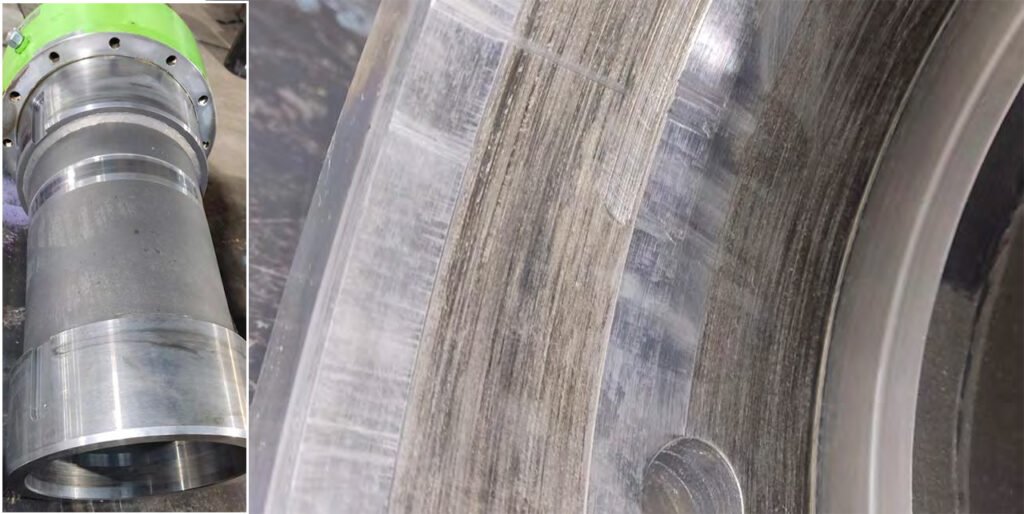
11. Defective bearing housing of the second stage drive shaft.
Wear of tapered roller bearing seats. The measurement results are presented in the appendix to the report "Appendix to Report SR-055-25: Bearing Seat Inspection Protocol in the Housing."
Wear of the cover thrust flange due to increased axial pressure of the outer race.
How does VRM operation cause bearing seat wear and thrust flange damage in the second-stage drive shaft housing?
1. Partial Load Operation and Load Zone Shifting
Wear of the tapered roller bearing seats can be driven by prolonged operation under partial or unstable load conditions in the VRM. When the mill does not operate at its designed load (e.g., low feed rate or inconsistent material layer), the internal load zones within the bearings shift irregularly instead of remaining stable. This causes uneven contact pressure distribution on the bearing outer race, which transfers non-uniform stress into the housing seat, leading to localized wear over time.
- Long-term operation below rated capacity
- Fluctuating feed rate causing shifting load zones
- Uneven grinding bed thickness
2. Start-Up Transients and Load Direction Reversal
During VRM start-up, especially under non-ideal conditions (e.g., material already present on the table), the drivetrain experiences rapid changes in load direction and magnitude. These transient forces are transferred into the bearing outer race and housing interfaces, causing micro-impact loading on the thrust flange. Repeated exposure to such transient events leads to progressive wear rather than immediate failure.
- Loaded starts or improper startup sequencing
- Frequent start-stop cycles
- Sudden engagement of grinding forces
3. Structural Flexibility of Mill Foundation and Load Redistribution
Unlike rigid standalone gear systems, VRM gearboxes are influenced by the flexibility of the mill foundation and supporting structure. Small deflections in the foundation or mill frame during operation can alter how forces are distributed through the gearbox housing. This results in uneven pressure on bearing seats and thrust surfaces, accelerating wear in specific areas rather than uniformly.
- Foundation settlement or structural deflection
- Non-uniform load path from mill to gearbox
- Interaction between mill frame and gearbox housing
4. Lubrication Flow Shadow Zones in Housing Interfaces
Wear in the bearing seat and thrust flange can also be influenced by areas within the housing that receive limited lubrication flow, often referred to as “shadow zones.” In VRM gearboxes, complex geometry and low-speed conditions can result in certain contact interfaces not receiving sufficient oil replenishment. This leads to boundary contact conditions and gradual material removal at the housing.
- Inadequate oil circulation to housing surfaces
- Low oil velocity in large gearbox cavities
- Complex internal geometry limiting oil access
5. Micro-Elastic Deformation Under Continuous Load Cycling
Over long operating periods, repeated loading and unloading cycles in VRM operation can cause micro-elastic deformation of the housing material itself. While each deformation is small, the cumulative effect can slightly alter the geometry of the bearing seat and thrust flange contact areas. This gradual change leads to loss of fit precision and promotes wear without a single obvious failure event.
- Continuous cyclic loading during grinding
- Long-term material fatigue at housing level
- Gradual geometric distortion rather than sudden damage
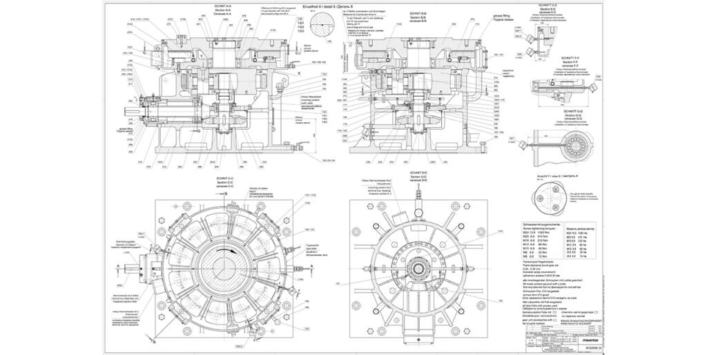
12. List of required parts.
| No. | Part List No. | Description | Qty |
| 1 | 1022 | Gearbox housing | 1 |
| 2 | 202 | Bevel gear shaft with bevel gear wheel | 1 |
| 3 | 210 | Bevel gear shaft housing | 1 |
| 4 | 212 | Cover of bevel gear shaft housing | 1 |
| 5 | 248 | Tapered roller bearing 31326X/DF | 2 |
| 6 | 250 | Spherical roller bearing 22326E1 | 1 |
| 7 | 252 | Bushing | 1 |
| 8 | 258 | Oil seal 160×130×15 FKM | 2 |
| 9 | 204 | Second stage drive shaft | 1 |
| 10 | 2042 | Key for second stage drive shaft | 1 |
| 11 | 232 | Spacer sleeve for second stage drive shaft | 1 |
| 12 | 234 | Spacer sleeve for second stage drive shaft | 1 |
| 13 | 236 | Bearing housing of second stage drive shaft | 1 |
| 14 | 240 | Bearing housing cover of second stage drive shaft | 1 |
| 15 | 2362 | Hex socket screw M12 | 12 |
| 16 | 2402 | Hex socket screw M12 | 12 |
| 17 | 288 | Cylindrical roller bearing NU 226 ECJ | 1 |
| 18 | 290 | Tapered roller bearing 32030X/DF | 1 |
| 19 | 294 | Retaining ring | 1 |
| 20 | 242 | Gear coupling | 1 |
| 21 | 292 | Retaining ring | 1 |
| 22 | 117 | Oil pipe | 1 |
| 23 | 122 | Oil pipe | 1 |
| 24 | 121 | Oil pipe | 1 |
| 25 | 116 | Oil pipe | 1 |
| 26 | 118 | Oil pipe | 1 |
| 27 | 119 | Oil pipe | 1 |
| 28 | 120 | Oil pipe | 1 |
| 29 | 1161 | Bolt M6 | 2 |
| 30 | 302 | Sun gear | 1 |
| 31 | 304 | Planet gear | 3 |
| 32 | 350 | Planet bearing NJ 232 ECML/C3 | 6 |
| 33 | 356 | Spacer ring for planet gears | 6 |
| 34 | 357 | Spacer ring for planet gears | 6 |
| 35 | 352 | Retaining ring for planet gears | 6 |
| 36 | 306 | Ring gear | 1 |
| 37 | 354 | Ring gear fixing bolt M24 | 32 |
| 38 | 450 | Spherical roller bearing 23064 CC/W33 | 1 |
| 39 | 408 | Spacer ring | 1 |
| 40 | 192 | O-ring seal | 1 |
| 41 | 103 | Hex socket screw M24 | 22 |
| 42 | 403 | Splined insert | 1 |
| 43 | 404 | Dowel pins | 13 |
| 44 | 4062 | Hex socket screw M24 | 8 |
| 45 | 440 | O-ring seal | 1 |
| 46 | 441 | O-ring seal | 1 |
| 47 | 152 | Breather | 1 |
| 48 | 153 | Breather | 1 |
| 49 | 110 | Plain bearing housing cover | 1 |
| 50 | 1102 | Cover gasket | 4 |
| 51 | 127 | Oil pipe gasket | 8 |
| 52 | 1301 | Gasket | 1 |
| 53 | 194 | Gasket | 1 |
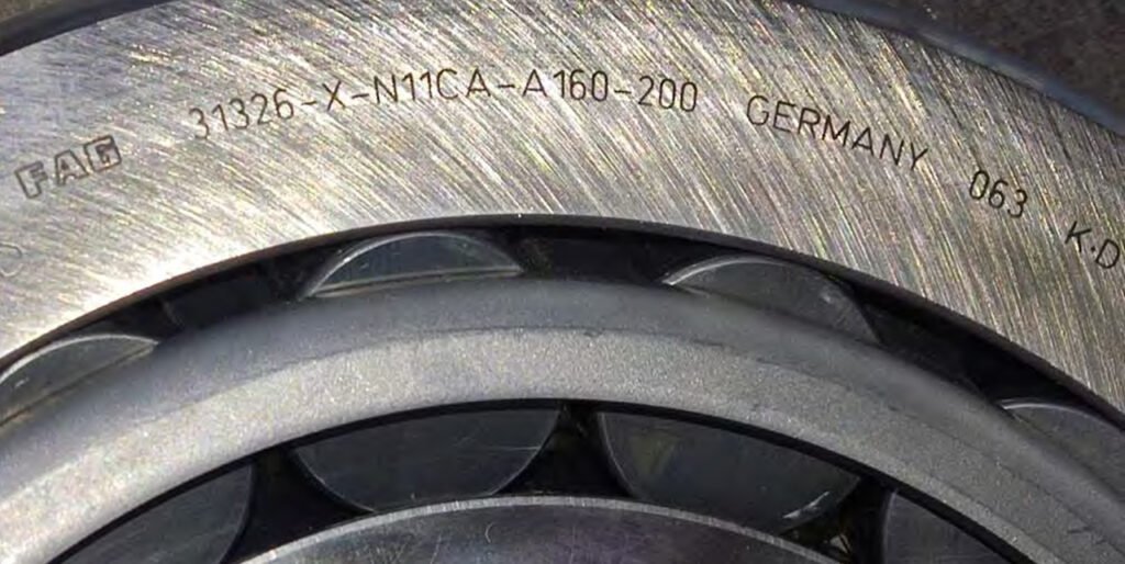
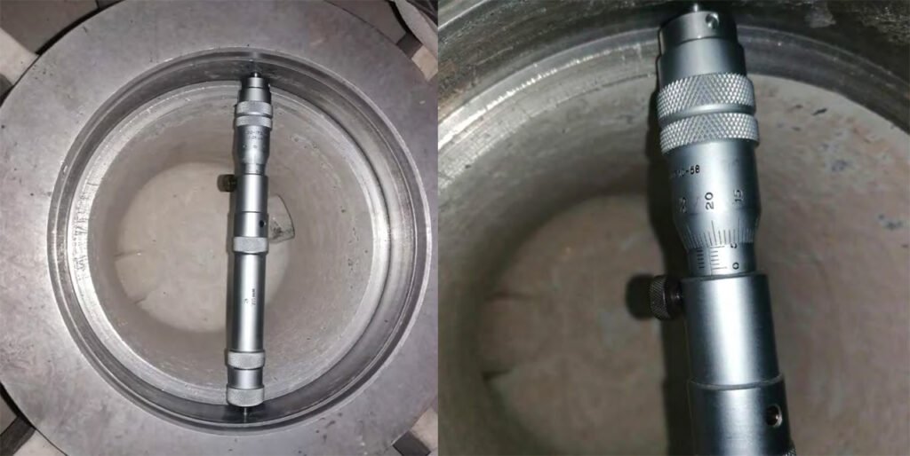
14. Appendix to Report SR-055-25: Bearing Seat Measurement Protocol
| Item | Details |
| Gearbox Type | Bevel-Planet |
| Number of Stages | 2 |
| Model / Name | KL2 0320/300-SS27-AKS320-11 |
| Manufacturer | David Brown Santasalo |
| Inspection Location | Promprivod TOO Service Center |
| Contractor | M.A. Klyuchnikov |
| Ambient Temperature | 20°C |
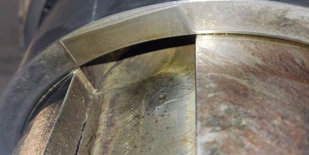
Figure 1 – Diagram of bearing seat measurements
Figure 2 – Directions of measurement relative to the longitudinal axis of the gearbox
Measurement directions relative to the longitudinal axis of the gearbox. The determination of permissible deviations should be calculated directly for the bearing's design position zones in the housing (sections 1-1, 2-2, 3-3, 4-4). The measurement results are summarized in tables. The determination of permissible deviations should be calculated directly for the bearing's design position zones in the housing (sections 1-1, 2-2, 3-3, 4-4). The measurement results are summarized in tables.
| Measurement Section | 1-1 | 2-2 | 3-3 | 4-4 |
| I–I | 280.02 | 280.02 | 280.01 | 280.02 |
| 280.01 | 280.02 | 280.02 | 280.02 | |
| II–II | 280.06 | 280.06 | 280.04 | 280.04 |
| 280.05 | 280.04 | 280.05 | 280.06 | |
| III–III | 280.21 | 280.25 | 280.25 | 280.24 |
| 280.21 | 280.25 | 280.22 | 280.25 | |
| IV–IV | 280.17 | 280.17 | 280.13 | 280.13 |
| 280.17 | 280.17 | 280.13 | 280.14 |
| Measurement Section | 1-1 | 2-2 | 3-3 | 4-4 |
| I–I | 225.02 | 225.02 | 225.02 | 225.02 |
| 225.02 | 225.02 | 225.02 | 225.02 | |
| II–II | 225.02 | 225.02 | 225.02 | 225.02 |
| 225.02 | 225.02 | 225.02 | 225.02 | |
| III–III | 225.06 | 225.06 | 225.04 | 225.04 |
| 225.03 | 225.03 | 225.02 | 225.02 | |
| IV–IV | 225.02 | 225.01 | 225.02 | 225.01 |
| 225.02 | 225.01 | 225.02 | 225.01 |
| Measurement Section | 1-1 | 2-2 | 3-3 | 4-4 |
| I–I | 230.08 | 230.08 | 230.06 | 230.08 |
| 230.04 | 230.05 | 230.08 | 230.07 | |
| II–II | 230.22 | 230.22 | 230.19 | 230.18 |
| 230.22 | 230.22 | 230.19 | 230.20 | |
| III–III | 230.17 | 230.19 | 230.15 | 230.15 |
| 230.17 | 230.19 | 230.17 | 230.19 | |
| IV–IV | 230.04 | 230.05 | 230.04 | 230.05 |
| 230.04 | 230.05 | 230.02 | 230.03 |
Determining Permissible Tolerances
Industrial gearboxes are manufactured according to ISO standards, GOST 25346, and GOST 25347-82. Fits are selected according to one of two systems: the bore system or the shaft system. For example, it is recommended to select bearing fits according to the seventh quality, H7. We will determine the quality tolerance range according to the table for bores with nominal diameters of Ф280, Ф230, and Ф225 mm.
| Size Range (mm) | H7 (µm) | J7 (µm) | K7 (µm) | N7 (µm) | P7 (µm) | F8 (µm) | H8 (µm) | E9 (µm) | H9 (µm) | H11 (µm) |
| 80 – 120 | +35 / 0 | +17 / -17 | +10 / -25 | -10 / -45 | -24 / -59 | +90 / +36 | +54 / 0 | +159 / +72 | +87 / 0 | +220 / 0 |
| 120 – 180 | +40 / 0 | +20 / -20 | +12 / -28 | -12 / -52 | -28 / -68 | +106 / +43 | +63 / 0 | +185 / +85 | +100 / 0 | +250 / 0 |
| 180 – 250 | +46 / 0 | +23 / -23 | +13 / -33 | -14 / -60 | -33 / -79 | +122 / +50 | +72 / 0 | +215 / +100 | +115 / 0 | +290 / 0 |
| 250 – 315 | +52 / 0 | +26 / -26 | +16 / -36 | -14 / -66 | -36 / -88 | +137 / +56 | +81 / 0 | +240 / +110 | +130 / 0 | +320 / 0 |
| 315 – 400 | +57 / 0 | +28 / -28 | +17 / -40 | -16 / -73 | -41 / -98 | +151 / +62 | +89 / 0 | +265 / +125 | +140 / 0 | +360 / 0 |
| 400 – 500 | +63 / 0 | +31 / -31 | +18 / -45 | -17 / -80 | -45 / -108 | +165 / +68 | +97 / 0 | +290 / +135 | +155 / 0 | +400 / 0 |
We obtain the following values:
For a 225mm diameter, the limit values range from 225.00 to 225.046 mm.
For a 230mm diameter, the limit values range from 230.00 to 230.046 mm.
For a 280mm diameter, the limit values range from 280.00 to 280.052 mm.
Conclusion: According to the results of measurements and comparison with the permissible values, wear levels unacceptable for use were detected. The results are summarized in Table 5.
| No. | Designation | Nominal Diameter (mm) | Permissible Size (mm) | Recorded Maximum (mm) | Condition Assessment |
| 1 | A | 280 | 280.052 | 280.25 | Not acceptable / Worn |
| 2 | B | 225 | 225.046 | 280.06 | Not acceptable / Worn |
| 3 | C | 230 | 230.046 | 230.22 | Not acceptable / Worn |
FAQ Frequently Asked Questions about Plantary
Vertical roller mills (VRMs) handling materials such as hard coal, limestone, gypsum, and cement operate under extremely high loads and demanding conditions. To meet these requirements, planetary gearboxes are widely used due to their ability to transmit very high torque within a compact design.
For example, advanced gear units like the Santasaló KL2 series and tongli TL series—developed through close collaboration between gearbox manufacturers and mill producers—can deliver torque levels of up to 3,000 kNm. At the same time, they ensure long service life, high reliability, and reduced installation space compared to conventional gearbox designs.
The planetary configuration also provides better load distribution across multiple gears, improving efficiency and durability, which makes it ideal for heavy-duty grinding applications in modern VRMs.
Modern vertical roller mill planetary gearboxes are typically designed as 2-stage bevel-helical planetary units, combining high efficiency with compact structure. They are capable of transmitting power up to 4,000 kW, with gear ratios ranging from 20 to 45, and delivering nominal output torque of up to 3,000 kNm.
These gearboxes are available in a range of sizes (commonly around 10 variants) to suit different mill capacities. Advanced engineering features—such as optimized gear tooth profiles that account for deformation under full load—ensure reliable performance and long service life.
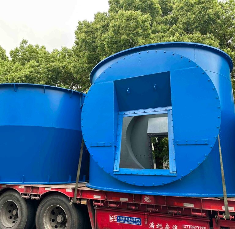
In addition, the design focuses on reduced noise and vibration levels, improving operational stability. A reinforced housing structure allows grinding forces to be directly transmitted to the foundation, minimizing stress on the gearbox itself and enhancing overall durability.
To enhance performance, reliability, and ease of maintenance, vertical roller mill planetary gearboxes can be equipped with a range of optional components.
These include a motor coupling with safety guard for secure power transmission, as well as a dedicated lubrication system featuring pumps and oil coolers to ensure proper thermal control and continuous operation. Integrated piping and instrumentation (I&C) can also be provided for seamless system integration.
For advanced monitoring, a PLC-based control system is often used to track lubrication performance and bearing temperatures in real time. Additionally, a condition monitoring system (CMaS) can be installed to assess gearbox wear status, enabling predictive maintenance and reducing the risk of unexpected downtime.
A KL2 planetary gearbox used in vertical roller mills is a complex, heavy-duty drive system composed of several key assemblies designed for high torque transmission and long service life. The primary components include:
1 Bevel gear stage (input stage) – Transfers power from the motor to the vertical axis of the gearbox through a bevel pinion and bevel gear set.
2 Planetary gear stages – Typically multi-stage, consisting of:
2.1 Sun gear (central driving gear)
2.2 Planet gears (multiple gears distributing load evenly)
2.3 Planet carrier (supports and transmits torque)
2.4Ring gear (internal gear fixed to the housing)
3 Main output shaft / carrier shaft – Delivers torque to the grinding table.
4 Rotary (grinding) table interface – Connects the gearbox output to the mill table, often via splined connections.
5 Splined coupling components – Ensure reliable torque transmission between internal shafts and external driven parts.
6 Locking pins – Secure the connection between gearbox output and the grinding table.
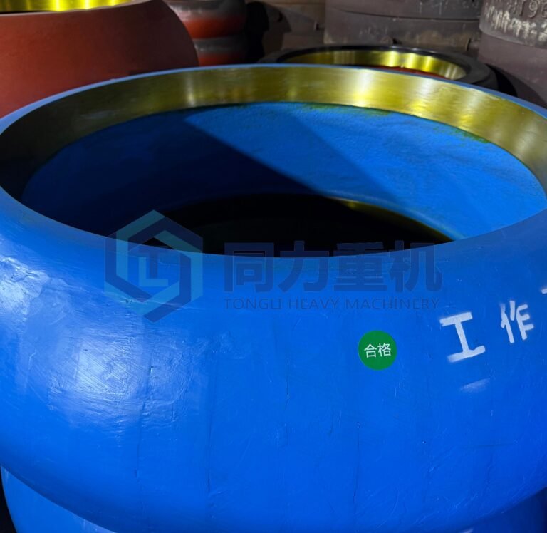
7 Bearing system – Includes radial and thrust bearings supporting high axial and radial loads.
8 Gearbox housing – A reinforced structure that absorbs and transfers grinding forces to the foundation.
9 Lubrication system – Includes oil pumps, distribution lines, filters, and coolers to ensure proper lubrication and heat dissipation.
10 Sealing and breather system – Maintains internal pressure balance and prevents contamination.
The heritage brands associated with David Brown Santasalo include a wide range of legacy gearbox manufacturers that have been integrated over time through mergers, acquisitions, and industry consolidation. These brands are still supported today for service, repair, and upgrades. Key heritage brands include: AEI (Associated Electric Industries), ASEA, Benoni Engineering Works, Bostock and Bramley, BTH (British Thomson-Houston), David Brown, GEC Alstom Gears, Hamworthy Transmissions, Hygate Transmissions, Jackson Gears, John Welsh, Maag Italia, Metso Drives, Metropolitan Vickers, Modern Wheel Drive, Paramount Gears, Power Plant Gears, Rauma Repola, Sadi Sala, Santasalo, Sonnerdale Richardson, Sauerwald, Turbine Gears, Valmet Power Transmissions, Weco, and Worm Gears. These heritage brands reflect decades of industrial gearbox expertise, and equipment from these manufacturers can still be maintained and optimized using modern engineering support.
We have extensive in-house expertise to service, repair, and upgrade a wide range of industrial gear units—regardless of the original manufacturer or model. Our capabilities cover leading global gearbox brands, including:
Brevini Gears, Falk Gears, Flender Gears, Hansen Transmissions, Lufkin Gears, Philadelphia Gears, Sumitomo Gears, and ZF Gears.
Whether your equipment requires routine maintenance, fault diagnosis, component replacement, or a complete overhaul, we provide reliable engineering support to ensure optimal performance, extended service life, and minimal operational downtime.
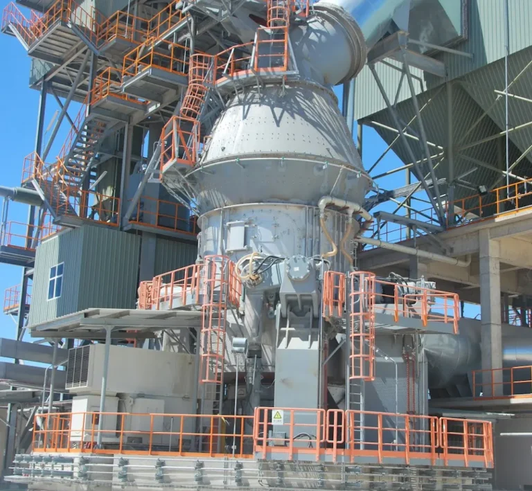
In a vertical roller mill, the planetary gearbox is mounted directly beneath the grinding table and converts the motor’s high-speed rotation into the slow, high-torque movement needed to turn the table. A typical motor runs at around 1000–1500 rpm, while the grinding table operates at roughly 20–40 rpm, so the gearbox’s main job is to reduce speed while significantly increasing torque.
The planetary design is used because it distributes the load across multiple planet gears rather than concentrating it on a single gear set. This allows the gearbox to handle the very high forces generated during grinding without becoming excessively large. At the same time, its vertical, coaxial structure matches the layout of the mill, with the motor above and the table directly connected below.
Beyond transmitting torque, the gearbox also carries the mechanical stresses coming from the grinding process itself. The pressure from the rollers is transferred through the table into the gearbox, meaning it must withstand not only rotational forces but also continuous axial loads and shock from material variations. In practical terms, the gearbox enables a high-speed motor to drive a slow-moving, heavily loaded grinding table in a stable and controlled way over long operating periods.
Loesche does not manufacture gearboxes itself; it supplies the vertical roller mill (VRM) as a complete system and sources the gearbox from specialized manufacturers. In most standard configurations, especially in cement and slag grinding applications, the primary gearbox supplier is RENK AG.
In most standard installations, Loesche LM-series vertical roller mills are equipped with gearboxes from RENK AG, particularly the well-known KPBV, KPBVplus, and COPE series. For example, medium-to-large mills such as LM46.2 or LM56.4 are commonly paired with KPBV 150–240 range gearboxes, while larger units like LM63.3 or LM69.6 often use KPBVplus or the multi-drive COPE system for higher torque capacity and redundancy. These models are specifically engineered for VRM duty, combining a bevel stage with planetary stages to handle both torque transmission and the axial grinding forces from the mill.
That said, depending on project specifications, region, or retrofit history, Loesche mills are not limited to RENK gearboxes. Units from Flender have also been used, typically from their heavy-duty vertical mill drive portfolio (such as bevel-planetary gear units designed for cement mills). These are comparable in concept to RENK designs and are often selected in projects aligned with Siemens/Flender supply chains.
You may also encounter installations or replacements using gearboxes from David Brown Santasalo, especially in retrofit or service-driven scenarios. David Brown Santasalo provides large bevel planetary mill gear units tailored for VRMs, and they are frequently chosen when upgrading or replacing existing drives while keeping the original mill structure.
In addition, Moventas (now part of the same industrial gearbox landscape through restructuring) has supplied planetary gearbox solutions for vertical mills in certain projects, particularly older installations or region-specific supply chains. While less common than RENK in Loesche applications, their designs follow similar principles and can be found in some operating plants.
Overall, while RENK remains the dominant and most typical pairing with Loesche LM mills, mentioning alternative suppliers like Flender, David Brown Santasalo, and Moventas—especially in the context of retrofits, upgrades, or regional variations—reflects real-world project diversity and adds technical credibility.