


Introduction:
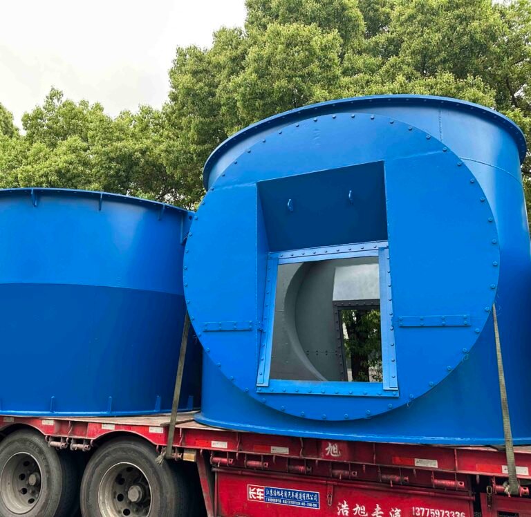
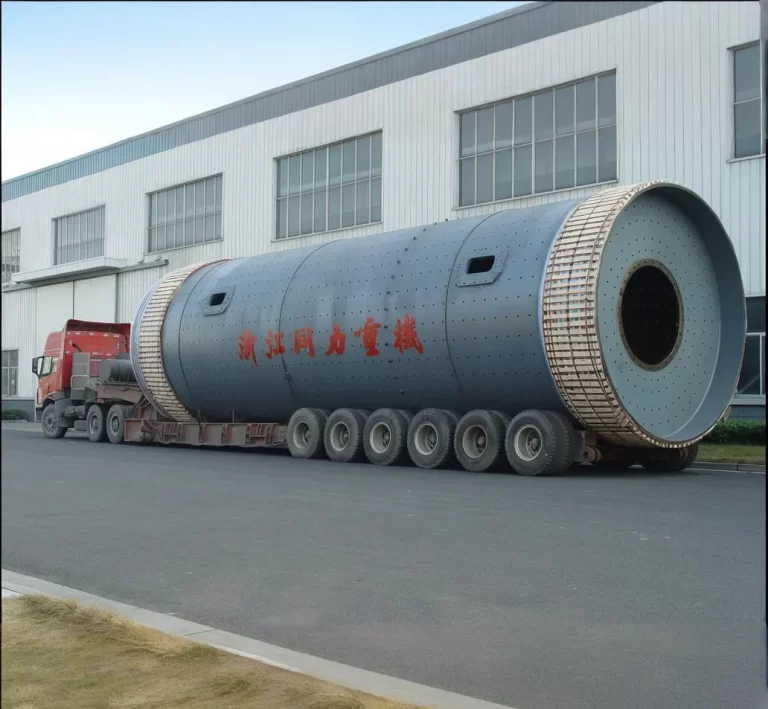
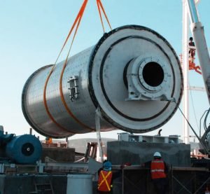
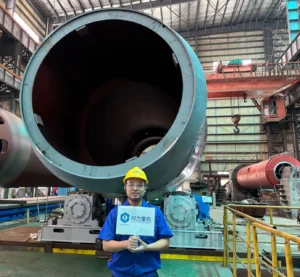
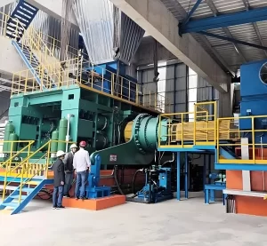
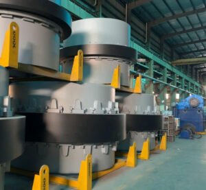
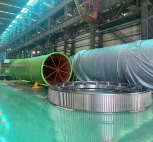
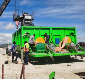
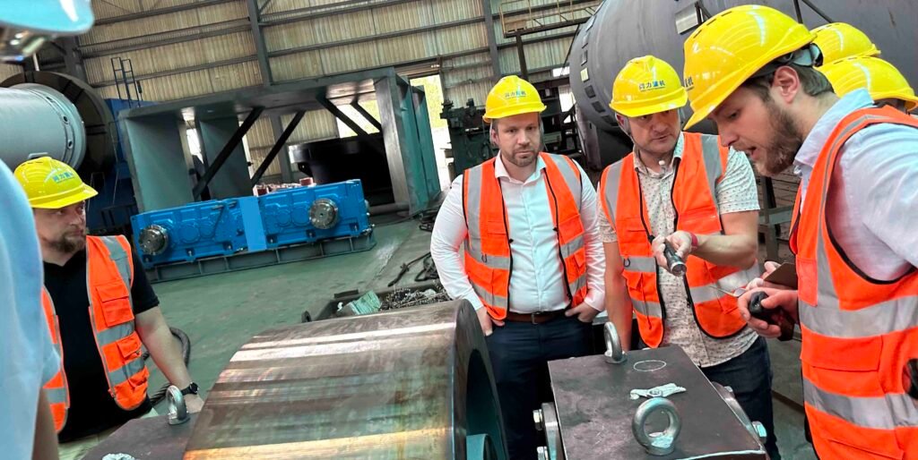
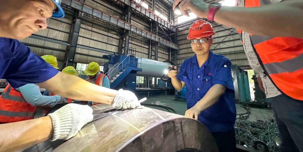
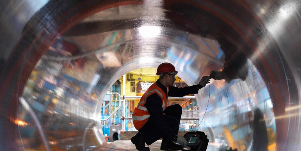
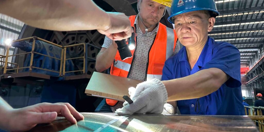
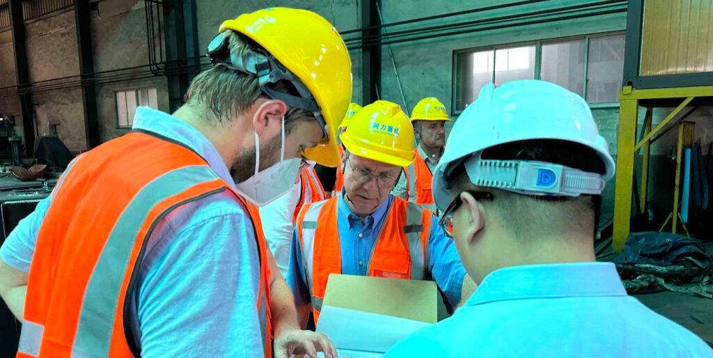
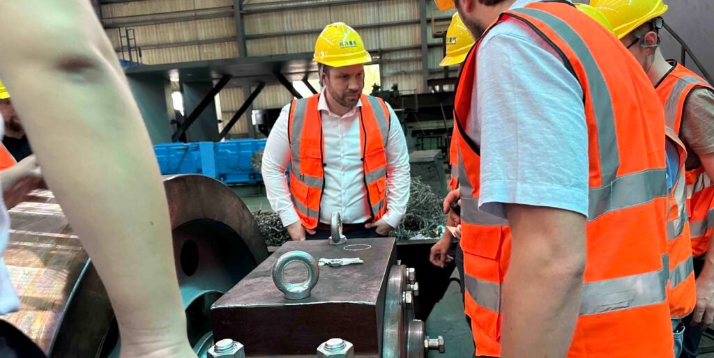
Cement machinery and equipment such as rotary kilns, vertical roller mills, and ball mills need to undergo NDT testing. The core reason is that many mechanical defects left over from welding and casting are difficult to detect with the naked eye at the beginning, but may expand rapidly over time. These equipment have been operating under harsh conditions of high temperature, high pressure, continuous rotation, and medium corrosion for a long time. Key parts such as the cylinder, tires, support wheels, vrm grinding roller, vrm rocker arm, ball mill head trunnion and welded joints are prone to hidden defects such as microcracks, wall thickness reduction, and fatigue damage due to factors such as thermal stress, friction, and corrosion. NDT testing can accurately detect these defects through ultrasonic, magnetic powder, penetration, and radiation technologies testing without destroying the structure of the equipment. It can not only warn of hidden dangers in advance and avoid catastrophic accidents, but also extend the life of the equipment and reduce maintenance costs. Today, customers from Europe Belgium came to Tongli to conduct a series of flaw detection and dimensional inspections on their customized cement and compound fertilizer equipment. We will use their process to introduce the factory acceptance test process of cement machinery in detail. Caution: this article is very very long, will take you approximately 3 hours to read through.
What is non-destructive testing's definition
Nondestructive testing (NDT) is a way to check materials, parts, and systems without breaking or damaging them. It helps keep things safe, reliable, and working well in many industries like construction, manufacturing, energy, and aerospace. NDT uses methods such as X-rays, sound waves, and magnetic tools to find problems early, stop failures, and make sure equipment lasts longer. Now the next question is who is able to do the NDT test? Can a random person do the NDT test? The answer is no, the person who perform the NDT has to be well tranied or certified, for example, Tongli's inspection staff is certified by CE and United State ASNT(the american society for non destructive testing)
What is ASNT: The American Society For Non-destructive Testing?
ASNT stands for the American Society for Nondestructive Testing. It is a professional organization that supports people and companies who work with nondestructive testing (NDT). NDT is the process of inspecting materials or equipment without damaging them. ASNT was founded in 1941 and is one of the most respected groups in the NDT industry. It sets international standards for NDT methods, testing procedures, and certification of NDT professionals. This helps ensure safety and quality in industries like cement, oil and gas, aerospace, construction, manufacturing, and power generation. ASNT also provides training, organizes events and conferences, publishes research and technical papers, and offers certifications like the ASNT Level I, II, and III. These certifications prove that an NDT technician has the skills and knowledge to do the job correctly. So now we have a understanding of who ASNT is, notice that all our TONGLI quality inspector are ASNT level II and level III certified!
What is intertek?
Intertek Group plc is a British multinational company headquartered in London, England, with a rich history spanning over 130 years, originally tracing its roots back to pioneering businesses in testing and certification, including one started by Thomas Edison. Today, Intertek is a global leader in providing Total Quality Assurance (TQA) solutions, which encompass Assurance, Testing, Inspection, and Certification (ATIC) services to a vast array of industries worldwide. With a network of over 1,000 laboratories and offices and more than 44,000 employees in over 100 countries, Intertek helps businesses ensure their products, processes, and systems meet rigorous quality, safety, sustainability, and performance standards, thereby mitigating risk, improving efficiency, and building trust for consumers and brands globally. So in breif Intertek provides non-destructive testing (NDT), materials testing and welding services, what is worth noting is Tongli is also Intertek certified!
What is a rotary kiln factory acceptance test FAT?
A Rotary Kiln Factory Acceptance Test (FAT) is a test done at the manufacturer’s workshop before the kiln is shipped to the customer. It checks if the equipment is made correctly and works as expected, during the FAT:
- The kiln parts are checked for size, materials, and quality.
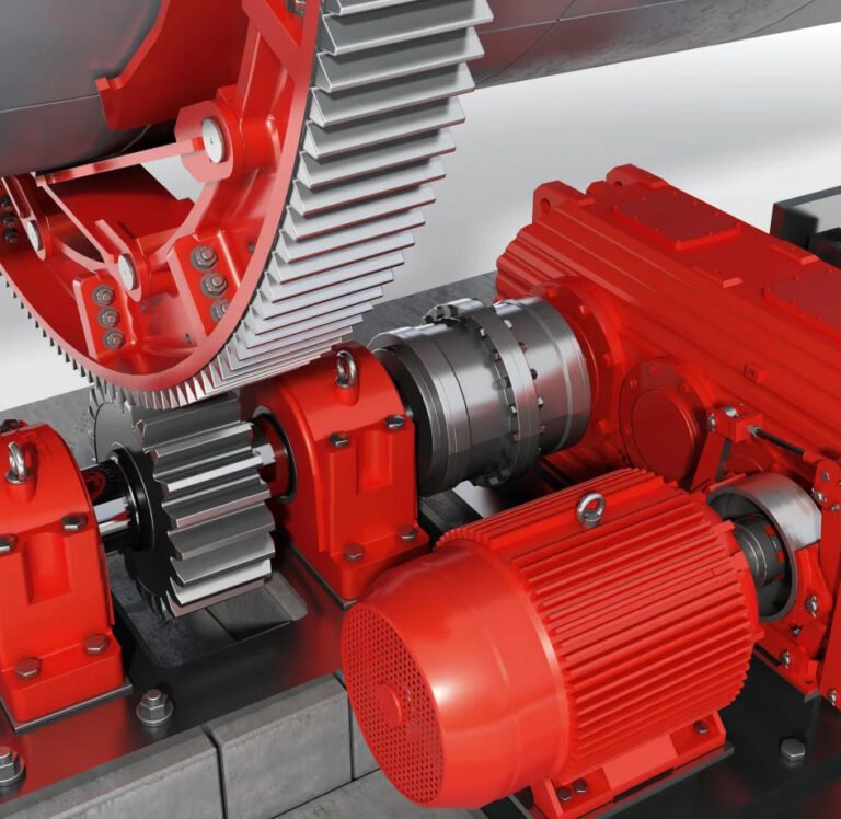
- Motors, gears, bearings, and seals are tested.
- The rotation, alignment, and balance may be checked.
- Control systems and safety features are inspected.
The customer or a third-party inspector often watches the test. After the FAT, a report is made. If the kiln passes, it can be packed and shipped to the site. This test helps avoid problems during installation and saves time later.
What are the main types of non-destructive testing?
Electromagnetic Testing (ET)
Electromagnetic Testing (ET) is a non-destructive testing technology based on the principle of electromagnetics. It applies an electromagnetic field to the material being tested and analyzes the changes in the electromagnetic response of the material due to internal defects, structural changes, or differences in physical properties to determine whether the material has defects or abnormalities. The core principle is to use phenomena such as electromagnetic induction, eddy current effect, and changes in magnetic permeability: when the electromagnetic field is applied through coils, probes, etc. and interacts with the object being tested, if there are defects or structural differences such as cracks, corrosion, inclusions, thickness changes, etc. in the object, it will interfere with the distribution of the electromagnetic field and produce eddy current disturbances, magnetic field leakage, impedance changes, etc. These changes can be captured by special instruments and converted into analyzable signal current, voltage, and magnetic field strength, thereby achieving the location, qualitative and even quantitative evaluation of defects.
What are the primary objectives of ET in rotary kiln industrial applications?
- Evaluate thinning of cylinder wall thickness and local corrosion/wear: The support ring (riding ring) of the rotary kiln is fixed to the cylinder by welding or riveting. After long-term stress, problems such as loose connection and cracking of welds may occur, resulting in relative sliding of the support ring and the cylinder, aggravating local wear.
- Detect defects in welded joints: The rotary kiln cylinder is usually welded by multiple sections of steel plates. The welded joints (circumferential seams and longitudinal seams) are stress concentration areas, which are prone to defects such as incomplete penetration, slag inclusions, pores, and welding cracks. These defects may expand rapidly under high temperature and rotational stress.
- Detect thermal fatigue cracks on the surface and near the surface of the cylinder: Under the alternating effects of high temperature (usually 300-1000℃) and periodic cooling, the rotary kiln cylinder will produce alternating stress due to thermal expansion and contraction, resulting in thermal fatigue cracks on the surface and near the surface (mostly axial or circumferential distribution), especially at the two ends of the cylinder (feed end, discharge end) and the contact area of the support wheel.
What are the primary method of ET?
- Eddy Current Testing (ECT): It detects defects by detecting the changes in eddy currents induced by alternating magnetic fields in conductive materials. It is suitable for surface and near-surface defect detection of metal pipes, plates, fasteners, etc. It is widely used in aerospace, automobile manufacturing, pipeline detection and other fields.
- Magnetic Particle Testing (MPT): Although it is often classified separately, it is essentially based on the electromagnetic principle - by magnetizing ferromagnetic materials, a leakage magnetic field is generated at the defects, and magnetic powder is adsorbed to form visible traces. It is mainly used to detect surface and near-surface cracks of ferromagnetic materials.
- Magnetic Flux Leakage (MFL): For ferromagnetic materials, corrosion and pits are judged by detecting the magnetic field leaked at the defects after magnetization. It is commonly used in the detection of oil and gas pipelines and storage tanks.
- Remote Field Eddy Current Testing: It is suitable for inner wall defect detection of thick-walled pipelines (such as power station boiler tubes). It can penetrate thicker pipe walls to achieve deep detection.
What are the 5 adventages of Electromagnetic Testing?
Non-contact detection:
No need to come into direct contact with the object to be detected, especially suitable for high temperature, high pressure, toxic or inaccessible environments (such as rotary kiln cylinder, high temperature pipeline, etc.), avoiding damage to the workpiece surface and reducing safety risks during the detection process.
High sensitivity to surface and near-surface defects:
It can accurately detect tiny cracks, pores, slag inclusions and other defects on the surface and near the surface of metal materials. For example, eddy current detection can identify micron-level cracks, and magnetic particle detection can intuitively display opening defects. It is suitable for fields such as aerospace and automobiles that require extremely high precision of parts.
Fast detection speed and automation:
With the help of probe scanning or automated equipment, large-area workpieces (such as pipes and plates) can be quickly detected, and the data can be recorded and analyzed in real time, which is suitable for online quality control of production lines and improves detection efficiency.
Applicable to a variety of materials and working conditions:
It can detect not only ferromagnetic materials (such as carbon steel and alloy steel), but also non-ferromagnetic metals (such as aluminum, copper, and austenitic stainless steel); at the same time, it can work in complex environments such as humidity and oil pollution, and has strong adaptability.
Can evaluate material properties:
In addition to detecting defects, it can also analyze the material's electrical conductivity, magnetic permeability, hardness, heat treatment status, etc. through electromagnetic signals, providing multi-dimensional data for material quality assessment (such as judging the purity of metal materials or the uniformity of heat treatment).
What are the 5 limitations of Electromagnetic Testing in NDT
Limited ability to detect deep defects:
The penetration depth of electromagnetic signals is affected by material properties (such as conductivity, magnetic permeability) and detection frequency. Usually, it can only effectively detect surface and near-surface defects (generally no more than a few millimeters in depth), and has low sensitivity to deep defects in thick-walled workpieces (such as cracks inside thick steel plates).
Limited by materials and workpiece shapes:
Electromagnetic detection cannot be used for non-conductive materials (such as plastics and ceramics);
Workpieces with complex shapes (such as special-shaped parts, parts with deep holes or grooves) are prone to detection blind areas due to uneven magnetic field distribution, affecting the accuracy of defect identification.
Susceptible to interference factors:
Factors such as workpiece surface roughness, coating thickness, temperature changes, and surrounding magnetic fields (such as electromagnetic interference in the environment) may interfere with the detection signal, resulting in misjudgment or missed detection. It is necessary to pre-treat the workpiece surface in advance (such as removing thick coatings) and optimize the detection environment.
High skill requirements for operators:
The interpretation of the test results depends on the analysis experience of electromagnetic signals. The signal characteristics of different types of defects (such as cracks and pores) may be similar. If the operator is inexperienced, it may lead to misjudgment of defects or incorrect grade assessment.
It is difficult to accurately quantify defect size:
Although the defect position can be located, it is difficult to accurately quantify the depth, length and other dimensions of the defect. It usually needs to be further verified in combination with other detection methods (such as ultrasonic detection), especially for complex morphological defects, the quantitative accuracy is limited.
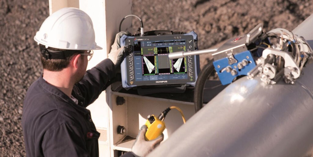
What is the basic working principle of Electromagnetic Testing
Electromagnetic induction and the interaction between electromagnetic fields and materials: alternating current (AC) is applied to a coil to generate a changing electromagnetic field. Technicians place an eddy current probe with a coil around the material, or a handheld probe on the material. The electromagnetic field can directly penetrate the material. If the object is a conductive material, the alternating electromagnetic field will induce eddy currents inside it, and defects in the material (such as cracks, wall thickness changes) will interfere with the distribution of eddy currents, causing the impedance or induced voltage of the detection coil to change; for ferromagnetic materials, a uniform magnetic field will be formed inside after magnetization. If there are surface or near-surface defects, the magnetic resistance at the defects will increase, causing part of the magnetic field to leak and form a leakage magnetic field, which can be captured by magnetic powder adsorption or sensors. Skilled operators can determine the presence and characteristics of discontinuities, such as cracks, corrosion, or inclusions.
What is Eddy Currents in ET?
Eddy current refers to the closed loop current generated inside a conductor when it is in a changing electromagnetic field. The formation of this current originates from the phenomenon of electromagnetic induction: according to Faraday's law of electromagnetic induction, the changing magnetic field will induce an electromotive force in the conductor, which in turn drives the free electrons to move in a directional manner, forming a circular current similar to a vortex in water, hence the name "eddy current". These currents are strongest on the surface of the material, gradually weaken as they go deeper, and eventually become too weak to be used. Surface defects have the greatest interference with these currents.
The size and distribution of eddy currents are related to many factors, including the intensity and frequency of the electromagnetic field, the conductivity and magnetic permeability of the conductor, and the shape and size of the conductor. For example, in metal materials, the presence of eddy currents will generate Joule heat (eddy current loss), which is used in scenes such as induction cooker heating; at the same time, the distribution of eddy currents will change due to defects (such as cracks, inclusions) or structural changes in the conductor, and changes in materials (such as thickness or conductivity) will affect the interaction of the magnetic field, which will be displayed on the test instrument. The results can be displayed in many ways, but the most common is the impedance plane display. This process helps identify problems in materials without causing any damage.
3 Factors that affect the depth at which eddy currents penetrate a material
- Electrical conductivity of materials: The higher the electrical conductivity of the material (good conductors such as copper and aluminum), the faster the eddy current decays and the shallower the penetration depth. This is because high electrical conductivity leads to stronger eddy current induction, and the anti-magnetic field generated by the eddy current weakens the penetration ability of the original magnetic field. For example, the electrical conductivity of copper is much higher than that of carbon steel, and its eddy current penetration depth is significantly less than that of carbon steel.
- Magnetic permeability of materials: For ferromagnetic materials (such as iron and carbon steel), higher magnetic permeability will enhance the concentration effect of the magnetic field, causing the eddy current to concentrate more on the surface of the material, thereby reducing the penetration depth. The magnetic permeability of non-ferromagnetic materials (such as stainless steel and aluminum) is close to that of air, and the eddy current penetration depth is relatively greater.
- Frequency of excitation current: The higher the frequency of the excitation current, the faster the alternating electromagnetic field changes, the more significant the skin effect of the eddy current (i.e., the current is concentrated on the surface of the material), and the shallower the penetration depth. For example, high-frequency eddy current testing is suitable for detecting small surface defects, while low-frequency testing can be used to detect deeper defects (but the sensitivity will be reduced).
5 Electromagnetic Testing Techniques Used in NDT
Electromagnetic Testing (ET) has many techniques to detect and measure flaws in materials. These techniques can be characterized by how the eddy currents cut into the material.
Pulsed Eddy Current Testing (PECT)
Pulsed Eddy Current Testing is an advanced variation of standard eddy current testing. Instead of using a continuous AC current, PECT uses a short burst (pulse) of direct current (DC) to magnetize the material. When the current stops, eddy currents are created in the test object. These eddy currents decay over time, and their decay rate is measured and analyzed to determine the condition of the material. PECT is very effective for detecting corrosion, especially in situations where insulation, coatings, or even concrete covers the surface. It can inspect thick materials and detect wall loss or thinning underneath surface layers—making it ideal for inspecting pipelines, tanks, or structural components without removing insulation. This reduces downtime and saves costs in industrial maintenance.
Remote Field Testing (RFT)
Remote Field Testing is a special electromagnetic method mainly used to inspect the inside and outside of ferromagnetic tubing, such as carbon steel heat exchanger and boiler tubes. A probe with a transmitter and receiver coil is inserted into the tube. The transmitter emits a low-frequency magnetic field that travels through the tube wall and returns to the receiver after passing through both the inner and outer surfaces. Because the magnetic field travels through the material twice, RFT is very sensitive to defects on both surfaces. It is especially effective for detecting wall loss, corrosion, and pitting. This method is commonly used in power plants, refineries, and petrochemical facilities for in-service inspection of tubes without needing to remove them from the system.
Electromagnetic Acoustic Transducer (EMAT)
EMAT is an advanced ultrasonic testing method that generates sound waves in conductive materials without direct contact. It works by using electromagnetic fields to create ultrasonic waves directly within the test material, instead of sending them through a separate transducer and couplant (gel or water). This allows inspections to be done on rough, dirty, hot, or painted surfaces. Because EMAT does not require surface preparation, it’s ideal for use in environments where conventional ultrasonic testing (UT) is difficult or impractical. Common applications include measuring wall thickness, detecting corrosion under coatings, and inspecting welds or hot steel in pipelines or structural components. EMAT is especially useful in automated or high-temperature settings, like in steel mills or power plants.
Eddy Current Testing (ECT)
Eddy Current Testing is one of the most widely used electromagnetic NDT techniques, especially for inspecting conductive materials like aluminum, copper, and steel. It uses a probe with coils that generate an alternating magnetic field. When this probe is placed near a conductive surface, it induces circulating electric currents—called eddy currents—inside the material. If there is a flaw such as a crack, corrosion, or other discontinuity near the surface, it will disrupt the flow of these eddy currents. The change in current flow is detected by the same probe and interpreted to locate and possibly size the defect. ECT is ideal for surface and near-surface inspection, such as aircraft parts, heat exchanger tubes, or welds. It offers immediate results, high sensitivity, and does not require couplants or special surface preparation.
Alternating Current Field Measurement (ACFM)
ACFM is a non-contact electromagnetic testing method used to detect and size surface-breaking cracks in metal structures. It works by applying an alternating current (AC) through a probe, which creates a magnetic field on the surface of the material. In areas without defects, this magnetic field is uniform. However, when there’s a crack or defect, the field becomes distorted. Sensors in the probe measure this disturbance to identify and size the crack accurately. One of the key advantages of ACFM is that it does not require the surface to be cleaned or stripped of coatings like paint or rust. This makes it especially useful for inspecting offshore oil platforms, pipelines, welded joints, and other painted or corroded surfaces. It also provides digital records, which are helpful for documentation and comparison in future inspections.
ET in the Real World – Cement Plant Equipment
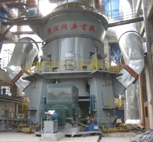
Rotary kilns, vertical roller mills, and ball mills are core machines in cement production, handling intense heat, high loads, and continuous operation. Over time, these machines are exposed to wear, thermal stress, material build-up, and structural fatigue. To keep the plant running safely and efficiently, non-destructive testing (NDT) is widely used to monitor their condition without dismantling the entire system.
For example, during a planned shutdown, technicians perform ultrasonic testing (UT) and magnetic particle inspection (MPI) on rotary kiln shells and tires to detect surface or subsurface cracks. Eddy current testing (ECT) or ACFM might be used to evaluate cracks near weld seams or high-stress areas. Similarly, vertical roller mill rollers and table liners are checked using ultrasonic thickness measurement and vibration analysis to assess wear and mechanical integrity.
Ball mills, which grind clinker and other materials, are also subject to gear wear and shell deformation. NDT methods such as dye penetrant testing (DPT) or laser alignment checks are applied to spot cracks in trunnions, pinions, and mill liners. These inspection results help maintenance teams schedule timely repairs or part replacements—reducing the risk of catastrophic failure, avoiding unplanned downtime, and keeping cement production on track.
Magnetic Particle Testing (MT)
Magnetic Particle Testing (MPT) for cement equipment is a non-destructive testing technology for surface and near-surface defects of carbon steel and alloy steel parts commonly used in cement production. It is used to detect discontinuities on the surface and near-surface of ferromagnetic materials. The principle is to apply a magnetic field to the inspected part through a coil, so that the defects, cracks, pores, and unfused surfaces on the surface and near-surface of the material will generate leakage magnetic fields. These leakage magnetic fields will interfere with the magnetic field and generate leakage magnetic fields. Ferromagnetic particles are attracted by these leakage magnetic fields to form visible discontinuity traces, thereby intuitively displaying the location, shape and size of the defects. This technology has the advantages of simple operation, fast detection speed, and high sensitivity (micron-level cracks can be detected). It is widely used in the detection of key components of cement equipment, such as rotary kiln cylinder welds, support wheels and wheel belt surfaces, reducer gears, couplings, etc. It is especially suitable for quickly locating hidden dangers that may affect the safe operation of equipment in harsh environments such as high temperature and dust, ensuring the continuity and reliability of cement production.
9 Advantages of Magnetic Particle Testing
Fast and relatively simple:
This process does not require complex signal conversion and analysis. After the magnetic field is established through the yoke, coil and other equipment, dry magnetic powder or wet magnetic suspension is applied (the particle size of the magnetic powder is usually 5-50μm, and the magnetic field strength needs to be matched). The magnetic traces at the defect can be formed within seconds to minutes. Its operation process complies with ASNT SNT-TC-1A and other standard specifications. The skill threshold for operators is lower than that of ultrasonic or radiographic testing. It is especially suitable for online sampling of batch components (such as bolts and shaft parts). The single-piece inspection cycle can be controlled within 10 minutes.
Economical and efficient:
The initial investment of magnetic particle testing equipment (such as portable magnetic yoke, black light, magnetic powder) is only 1/10-1/5 of that of radiographic testing equipment, and the cost of consumables (magnetic powder, carrier liquid) is low. Compared with ultrasonic testing, which requires coupling agent, and radiographic testing, which requires protective facilities, MT has extremely low auxiliary costs. It is particularly suitable for large-scale surveys of large structures (such as bridge bearings and pressure vessel welds). The unit inspection area cost is only 60%-70% of that of penetration testing.
Easy to operate and high detection efficiency:
No complicated pretreatment is required (only thick coating or oil stains on the surface need to be removed), the magnetic field can be quickly established through yokes, coils and other equipment, and detection can be achieved with dry magnetic powder or wet magnetic suspension. The detection time of a single weld or small component is usually completed within a few minutes. At the same time, magnetic traces can be directly observed with the naked eye without relying on complex signal analysis, which is suitable for rapid on-site screening, especially for complex environments with high dust and limited space such as cement plants.
Versatility:
Applicable to all ferromagnetic materials (iron, cobalt, nickel and their alloys, such as 45# steel, 20CrMnTi), regardless of the shape (plate, pipe, special-shaped parts) or size (from bolts with a diameter of 2mm to pipes with a length of tens of meters). By adjusting the magnetization method (axial magnetization, circumferential magnetization, composite magnetization), defects in different directions can be covered, such as circumferential magnetization for detecting radial cracks in the annular seam of the rotary kiln shell, and axial magnetization for detecting transverse cracks in the longitudinal weld.
Instant results:
After the magnetic trace is formed, it can be directly observed by naked eyes (visible light magnetic powder) or black light (fluorescent magnetic powder), without waiting for film development like X-ray detection, or waveform analysis like ultrasonic detection. The test results can be recorded in real time (photographing, recording), and the determination of defects can be completed on site, especially in emergency maintenance scenarios (such as equipment shutdown and maintenance), it can quickly decide whether to release or return for repair, greatly shortening the downtime.
Quantitative insights:
The length, width, and stacking density of the magnetic trace can be used to preliminarily determine the size and severity of the defect. For example, the length of the magnetic trace usually coincides with the actual length of the defect (error ≤10%), and the density of the magnetic trace reflects the leakage magnetic field strength (indirectly related to the depth of the defect). Combined with the comparison of standard test blocks (such as type A test blocks), the defects can be graded (such as the defect acceptance level in ISO 9712), providing a quantitative basis for quality assessment.
Highly sensitive to surface and near-surface defects:
Can accurately detect tiny cracks, unfused, pores and other defects on the surface and near-surface (usually ≤1mm deep) of ferromagnetic materials, and can even identify micron-level open cracks. The principle is that the leakage magnetic field at the defect has a strong adsorption to the magnetic powder, and the magnetic traces formed can directly reflect the defect shape, which is especially suitable for detecting fatigue cracks in stress concentration areas (such as heat-affected zones of welded joints and near machining tool marks), which is crucial for cement equipment that bears alternating loads (such as rotary kiln wheel belts and crusher spindles).
Defect display is intuitive and low cost:
The magnetic traces formed by the magnetic powder are highly consistent with the defect shape, and the location, direction and approximate size of the defect can be directly determined, providing a clear basis for subsequent maintenance (such as determining the scope of repair welding). In addition, the equipment investment (such as portable yoke, magnetic powder) and consumables costs are much lower than X-ray detection and ultrasonic detection, which is suitable for large-scale, normalized equipment inspections.
Surface and near-surface inspection:
Magnetic particle testing (MT) is based on the principle that a leakage magnetic field is generated at a defect after the ferromagnetic material is magnetized. It has extremely high sensitivity to surface and slight sub-surface defects (usually ≤1mm in depth). The intensity of the leakage magnetic field is positively correlated with the defect opening and depth, and can accurately capture micron-level cracks (such as hydrogen-induced cracks in the heat-affected zone of welding and fatigue cracks at the root of gear teeth). In particular, the detection rate of linear defects (such as cold working cracks and quenching cracks) is significantly higher than other surface inspection methods. This is because the gradient of the leakage magnetic field generated by linear defects is more obvious, and the adsorption force on magnetic powder is stronger.
10 Limitations of Magnetic Particle Testing
Only applicable to ferromagnetic materials:
Its detection principle relies on the leakage magnetic field generated after the material is magnetized, so it cannot be used for non-ferromagnetic materials (such as austenitic stainless steel pipes and aluminum alloy parts in cement equipment), which limits the scope of application.
Weak detection ability for deep defects and non-surface opening defects:
The leakage magnetic field intensity decays sharply with the increase of defect depth, and it can usually only effectively detect surface and near-surface defects with a depth of ≤1mm. It is difficult to identify defects deeply buried inside the material (such as cracks in the center of thick steel plates) or closed defects (such as unopened rolling cracks), and it is necessary to combine ultrasonic testing and other technologies for supplementary verification.
Poor environmental adaptability:
High temperature (>60℃) will cause the wet magnetic suspension to evaporate and the magnetic powder to aggregate; high humidity (relative humidity>85%) will cause the dry magnetic powder to absorb moisture and agglomerate, reducing fluidity; dusty environment (such as cement plant area) will contaminate the magnetic powder and interfere with magnetic trace identification. In addition, a strong magnetic field environment (such as an electromagnet nearby) will superimpose the external magnetic field, resulting in pseudo magnetic traces. Therefore, it is necessary to conduct detection in an area with an environmental magnetic field of ≤0.5mT, which increases the restrictions on on-site operations.
Requires mandatory demagnetization:
After magnetization, ferromagnetic materials will have residual magnetism (especially high magnetic permeability materials, such as electrical pure iron). Residual magnetism may cause chip adsorption in subsequent processing, affect precision assembly (such as bearing installation), or interfere with instrument readings (such as nearby magnetic sensors). According to the API 5L standard, the residual magnetism of the workpiece after detection must be ≤2mT (20 Gauss), and a demagnetization coil or demagnetization machine must be used for demagnetization. This step will increase the detection time by 10%-20%, and large components (such as 10,000-ton hydraulic press beams) require customized special demagnetization equipment, which is costly.
Limited by the shape of the workpiece and the direction of the magnetic field:
Complex geometric shapes (such as curved surfaces, edges and corners, and near deep holes) are prone to magnetic field distortion, which may cover real defects or form pseudo-magnetic traces; at the same time, the sensitivity of defect detection is closely related to the direction of the magnetic field (such as longitudinal cracks must be perpendicular to the direction of the magnetic field to produce obvious leakage magnetic fields). If the direction of the magnetic field is parallel to the direction of the defect, it may lead to missed detection. Therefore, multi-directional magnetization (such as cross yoke) is required to cover defects with different directions.
Greatly affected by environmental factors:
When there is a thick coating, rust, or oil on the surface of the workpiece, it will hinder the effective interaction between the magnetic powder and the leakage magnetic field, resulting in blurred magnetic traces; a humid environment may cause the magnetic powder to agglomerate, affecting the detection accuracy, so the detection surface needs to be pre-treated, which increases the operation steps.
Limited to ferromagnetic materials:
The core principle of magnetic particle detection is to use the leakage magnetic field at the defect to adsorb magnetic powder, and only ferromagnetic materials (such as iron, cobalt, nickel, and their alloys) can be effectively magnetized and generate a stable magnetic field. For non-ferromagnetic materials (such as austenitic stainless steel, aluminum alloy, and copper alloy), their relative magnetic permeability is close to 1 (equivalent to air), and they cannot form a leakage magnetic field sufficient to adsorb magnetic powder, so they are completely unsuitable. For example, 304 stainless steel pipe welds in cement equipment cannot be tested with magnetic particle detection, and penetration detection or eddy current detection must be used instead.
Strict surface treatment requirements:
The surface of the test object must be cleaned of contaminants such as oil, rust, oxide scale, and thick coating (thickness exceeding 50μm will significantly attenuate the leakage magnetic field), otherwise it will hinder the contact between magnetic powder and leakage magnetic field, resulting in missed defects. According to the ASME V standard, the surface roughness must be ≤Ra 25μm, and there must be no covering impurities. In actual operation, pre-treatment steps such as grinding and solvent cleaning are often required, which will increase the total detection time by 30%-50%. Especially for equipment that has been running for a long time (such as rotary kiln cylinders), special tools are required to clean the high-temperature oxide layer on the surface, further increasing the operating cost.
Significant depth limitation:
The effective detection depth of magnetic particle testing depends on the magnetic permeability of the material and the defect morphology. It can usually only reliably detect surface and near-surface defects with a depth of ≤1mm. This is because the leakage magnetic field strength decays exponentially with the increase of defect depth - when the defect depth exceeds 10% of the material thickness or is greater than 1mm, the leakage magnetic field is too weak to absorb magnetic powder to form identifiable magnetic traces. For example, for a 20mm thick carbon steel flange, magnetic particle testing is difficult to detect internal cracks less than 3mm from the surface, and ultrasonic testing is required for additional verification.
Health and safety risks:
Dry magnetic powder (especially micron-level ferromagnetic powder) is easily inhaled into the respiratory tract, and long-term contact may cause pneumoconiosis, so a dust mask must be worn; fluorescent agents (such as rhodamine B) in fluorescent magnetic powder are potentially irritating and must be cleaned in time after contact with the skin; the strong magnetic field (>0.5T) of the magnetizing equipment may interfere with medical implants such as pacemakers, and warning signs must be set up in the operating area, all of which increase the complexity of safety management.
How does Magnetic Particle Testing Work?
To understand how magnetic particle testing works, it helps to know some basic magnetism. We all know that magnets attract certain metals, such as iron, nickel, and cobalt, but not others, such as aluminum or copper. Magnets come in different shapes and sizes and have different strengths. In fact, the earth itself is a giant magnet.
In magnetic particle testing, a magnetic field is first applied to the metal part being inspected. Technicians typically use a device like a yoke, coil, or probe to magnetize the part. This magnetic field can be generated using either alternating current (AC) or direct current (DC). AC is good for detecting surface defects, while DC is better for finding defects below the surface.
Once the metal part is magnetized, magnetic particles are sprinkled on its surface. The magnetic particles can be dry or mixed in a liquid to form a magnetic suspension. If there are cracks, pores, or other defects on the metal surface, these areas will interrupt the magnetic field, forming a "leakage field." The magnetic particles are attracted to these leakage areas and accumulate at the location of the defect, forming a visible indication.
Experienced inspectors can determine the approximate location, direction and size of defects by observing the shape and position of these magnetic particles. Magnetic particle testing is a very effective method, commonly used to detect surface or near-surface defects in welds, castings, forgings and other key parts, especially for ferromagnetic materials.
How Magnetic Fields Reveal Material Defects: Principle Analysis in Magnetic Particle Testing
In magnetic particle testing (MT), the magnetic field is not only an external energy source, but also has important interactions with the internal structure of the material being tested. When there are discontinuities such as cracks, pores or inclusions in the magnetized material, the originally uniformly flowing magnetic field will be "interrupted" and leak out from the defect. This phenomenon is called magnetic flux leakage. You can imagine the magnetic flux as a flowing stream, and the defects inside the material are like stones in the stream. Water (magnetic flux) bypasses the stone and creates turbulence; similarly, the magnetic field will "leak" from the crack or void when it encounters it, forming a local magnetic anomaly. To show these anomalies, technicians will sprinkle a layer of ferromagnetic powder (either dry powder or wet powder suspended in liquid) on the surface of the magnetized material. When the magnetic flux leaks at the defect, the powder will be attracted and accumulate above the defect, forming a visible indication. This process is like the experiment we did as children, where we sprinkled iron filings around a magnet and they would align along the magnetic lines of force, except that here, the iron powder is attracted by the "abnormal magnetic field". This phenomenon can be divided into two key parts:
- Flux Leakage: When the magnetic field encounters a discontinuity in the material (such as a crack), it leaks from there, forming a local area of enhanced magnetic field.
- Particle Attraction: Ferromagnetic particles are automatically attracted to these abnormal areas, forming a "visual mark" of defects on the surface.
3 Types of Materials in MT
In magnetic testing, the response characteristics of materials to magnetic fields are derived from the electromagnetic structure inside their atoms: atoms are composed of positively charged nuclei and electrons orbiting the nucleus. The orbital motion and spin motion of electrons jointly generate magnetic moments, and the overall magnetic nature of the material is the collective behavior of atomic magnetic moments under the action of an external magnetic field. According to the arrangement of atomic magnetic moments and the intensity of the response to the external magnetic field, materials can be divided into three categories:
Diamagnetic materials:
The magnetic moments generated by the electron spin and orbital motion inside its atoms are completely offset, and the overall magnetic moment is zero. When exposed to an external magnetic field, a weak magnetic moment opposite to the external magnetic field is induced, showing an extremely weak repulsive force (the magnetic susceptibility χ is negative, usually in the order of -10⁻⁶~-10⁻⁹). After the external magnetic field is removed, the induced magnetic moment disappears immediately, and there is no residual magnetism. For example, copper, gold, bismuth, etc., their diamagnetism originates from the Lorentz force effect of electron orbital motion in an external magnetic field. This property makes it a shielding material in high-precision magnetic field measurement.
Paramagnetic materials:
Atoms have an inherent magnetic moment that is not offset (such as the presence of unpaired electrons), but thermal motion causes the magnetic moment to be disordered, and the overall magnetism is weak. Under the action of an external magnetic field, the magnetic moment will be slightly oriented along the direction of the magnetic field, showing a weak attraction (the magnetic susceptibility χ is positive, usually in the order of 10⁻⁶~10⁻³), but the magnetization intensity is much lower than that of ferromagnetic materials. After the external magnetic field is removed, thermal motion restores the magnetic moment to disorder, and there is no remanence. For example, the paramagnetism of aluminum, platinum and some austenitic stainless steels (such as 304) is mainly contributed by the spin magnetic moment of unpaired electrons, and is often used in precision devices that require weak magnetic response.
Ferromagnetic materials:
There are "magnetic domains" formed by the parallel arrangement of atomic magnetic moments inside. In the absence of an external magnetic field, the magnetic domains are randomly oriented and the overall magnetism is not obvious; under the action of an external magnetic field, the magnetic domains will expand and rotate along the direction of the magnetic field, generating extremely strong magnetization intensity (magnetic susceptibility χ can reach 10³~10⁶), showing a strong attraction. If the external magnetic field is strong enough, the material can reach magnetic saturation and retain significant remanence (i.e., "permanent magnetic characteristics") after the external magnetic field is removed. This is due to the irreversible reorganization of the magnetic domain structure. Iron, cobalt, nickel, and most carbon steels and alloy steels belong to this category. Their strong magnetism makes them the core materials of magnetic devices such as motors and permanent magnets, and they are also the main applicable objects of non-destructive testing technologies such as magnetic particle testing.
4 Types of Magnetic Fields in MT
Circular Magnetization
Circular magnetization is to pass current directly into the workpiece (such as shaft parts) or through the central conductor (such as the inner wall of the pipe) to make the magnetic field circumferentially distributed along the workpiece to form circular magnetic lines of force. Its core advantage is that it can efficiently detect longitudinal discontinuities (i.e., the direction of the defect is parallel to the axis of the workpiece, such as axial cracks and longitudinal lack of fusion), because such defects will vertically cut the circular magnetic lines of force and produce a strong leakage magnetic field. In cement machinery, it is often used to detect the circumferential welds of the rotary kiln shell (current needs to be passed through the central conductor, and the magnetic field surrounds the weld), which can accurately detect longitudinal cracks in the weld; it is also suitable for the detection of ball mill main shafts, and can identify axial fatigue cracks on the shaft surface caused by long-term heavy loads.
Longitudinal Magnetization
Longitudinal magnetization places the workpiece in a coil or uses a yoke to bridge the workpiece surface, so that the magnetic field is distributed along the length of the workpiece (the magnetic field lines are parallel to the axis). It is mainly used to detect transverse discontinuities (the defect direction is perpendicular to the workpiece axis, such as circumferential cracks and transverse pores). Such defects will vertically cut the longitudinal magnetic field lines, forming a significant leakage magnetic field.
In cement machinery, the yoke method is widely used in the detection of vertical mill roller journals, which can detect circumferential cracks caused by friction; when detecting the outer surface of the rotary kiln wheel belt, longitudinal magnetization can effectively identify transverse fatigue cracks caused by the contact between the wheel belt and the supporting wheel, ensuring the safety of the supporting components.
Alternating Current (AC)
AC magnetization uses alternating current to generate a magnetic field. Its magnetic field energy is concentrated on the surface of the workpiece (the skin effect is significant). The surface magnetic field intensity is high but the penetration depth is shallow (usually ≤1mm). The detection sensitivity of surface defects (such as open cracks and mechanical scratches) is extremely high. The dynamic change of AC magnetic field can also enhance the fluidity of magnetic powder and make the magnetic trace clearer.
In cement machinery inspection, it is often used for surface crack detection of ball mill liner bolts - bolts are prone to surface fatigue cracks due to frequent vibration, and AC magnetization combined with dry magnetic powder can quickly locate them; it is also suitable for vertical mill reducer gear tooth surface inspection, and can identify fine surface cracks caused by meshing wear.
Circular Magnetization
DC magnetization generates a constant magnetic field through direct current. Its magnetic field has a large penetration depth (up to several millimeters) and can effectively detect near-surface discontinuities (such as subcutaneous pores and near-surface unfused). In practical applications, it is often used in conjunction with wet magnetic suspension (magnetic powder suspended in liquid). The liquid carrier can make it easier for magnetic powder to penetrate into tiny defects and improve the visibility of magnetic traces. In cement machinery, it is suitable for detecting near-surface defects of rotary kiln support wheels. Support wheels bear the weight of the kiln body for a long time, and subcutaneous cracks are easily generated near the surface due to contact stress. DC magnetization can accurately identify them. When inspecting the hub of the large gear of the ball mill, near-surface inclusions or shrinkage holes formed during the casting process can be found to avoid fractures caused by stress concentration.
3 Particle Types in MT
In magnetic particle inspection, the type of magnetic powder needs to be selected according to the surface state of the inspection object, defect sensitivity requirements and environmental conditions, mainly including the following three categories:
Visible magnetic powder (Visible Particles)
Visible magnetic powder is usually black (iron oxide-based), red or gray (chromium oxide-based) and other high-contrast pigment-colored particles. The magnetic traces can be directly observed by the naked eye without special light sources. According to the application form, it can be divided into dry visible magnetic powder and wet visible magnetic powder: Dry visible magnetic powder particles are coarse (usually 50-150μm) and have good fluidity. They are suitable for the inspection of rough surfaces (such as castings and forgings). Their loose state can quickly fill surface defects to form clear magnetic traces; in cement machinery, they are often used for on-site inspection of rough surfaces such as ball mill liners, and are easy to operate and portable.
Fluorescent magnetic powder (Fluorescent Particles)
Fluorescent magnetic powder is a magnetic particle coated with fluorescent dyes (such as fluorescein and rhodamine) on the surface, usually suspended in water or oil-based carriers to form a wet magnetic suspension. During the inspection, it is necessary to cooperate with ultraviolet light (UV-A, wavelength 320-400nm) irradiation. The magnetic powder will emit strong fluorescence (such as yellow-green, orange-red), and the recognition sensitivity of tiny defects (such as microcracks, pinholes) is much higher than that of visible magnetic powder (which can detect surface defects ≤0.1mm). In the inspection of precision parts of cement machinery, such as the root of the rotary kiln transmission gear and the surface of the piston rod of the vertical mill hydraulic cylinder, fluorescent magnetic powder can accurately detect fine cracks caused by fatigue or corrosion, and is especially suitable for use in dark sites or workshop environments.
Dual-Use Particles
Dual-Use magnetic powder is a special particle with dual coatings of visible pigments and fluorescent dyes. The detection mode can be flexibly switched according to the detection needs: under natural light, more obvious defects can be identified through visible colors, and under ultraviolet irradiation, fluorescence can enhance the detection ability of tiny defects. This kind of magnetic powder reduces the operation steps of changing the type of magnetic powder and improves the detection efficiency.
In the comprehensive inspection of cement machinery (such as large-area rough inspection and key-part fine inspection of the rotary kiln cylinder), dual-purpose magnetic powder can take into account both efficiency and sensitivity and adapt to complex inspection scenarios.
3 Magnetic Particle Testing Techniques Used in NDT
Magnetic particle testing (MT) applies magnetic fields in different ways and optimizes the defect display effect. It can be divided into three categories: contact detection, coil detection and portable detection. Each type of technology is designed for specific scenarios and workpiece shapes, and each has its own focus in industrial inspection:
Contact Testing
Contact testing applies a magnetic field by direct contact between the probe and the workpiece surface. The magnetic field is highly concentrated and suitable for precise detection of local areas. The core technologies include:
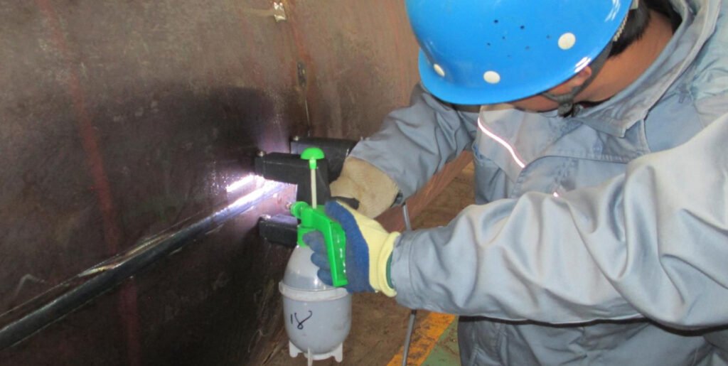
- Yoke Testing: Use a handheld yoke (U-shaped or horseshoe-shaped electromagnet) to bridge the surface of the workpiece, and form a longitudinal magnetic field through the two poles of the yoke. Its advantage is that it does not require power to penetrate the workpiece, has strong adaptability to irregular-shaped parts (such as special-shaped flanges and complex castings), and the direction of the magnetic field can be flexibly changed by adjusting the yoke placement angle. In cement machinery, it is often used for local detection of vertical mill disc supports, which can quickly locate cracks caused by stress concentration; during on-site maintenance, it is also very convenient to detect curved surfaces such as the shoulder of the rotary kiln support wheel.
- Prod Testing: Two conductive contacts (copper or steel) are contacted to the workpiece surface. After current is passed, a circumferential magnetic field is formed between the contacts (magnetic lines surround the current path), which is suitable for circumferential magnetization of local areas (such as the heat-affected zone of welds). Its magnetic field strength can be adjusted by current, and the detection efficiency of local repair welding area of small workpieces or large equipment is extremely high. For example, the detection of local welds of the flange of the feed port of a ball mill can accurately detect tiny cracks caused by welding stress.
Coil Testing
Coil testing places the workpiece inside the coil and uses the magnetic field generated by the coil to achieve overall magnetization. It is suitable for batch detection of regular-shaped workpieces, mainly including:
- Circular Coil Testing: Place cylindrical workpieces (such as shafts, rods, and tubes) coaxially into the circular coil, and the coil is energized to generate a longitudinal magnetic field, which can efficiently detect transverse defects (such as circumferential cracks) on the surface of the workpiece. Its magnetic field has good uniformity and is suitable for batch detection of standard parts. For example, for cylindrical parts such as conveyor rollers and hydraulic piston rods in cement machinery, it can realize automated assembly line detection to ensure consistency in defect detection.
- Solenoid Coil Testing: The solenoid is composed of long straight coils, and the magnetic field covers a wider range, which is suitable for the overall magnetization of large cylindrical workpieces or components (such as long shafts and large pipelines). Compared with toroidal coils, its magnetic field has a greater penetration depth and can detect near-surface defects. For example, when the support shaft of a rotary kiln is inspected as a whole, near-surface inclusions or cracks caused by forging defects inside the shaft can be found.
Portable Testing
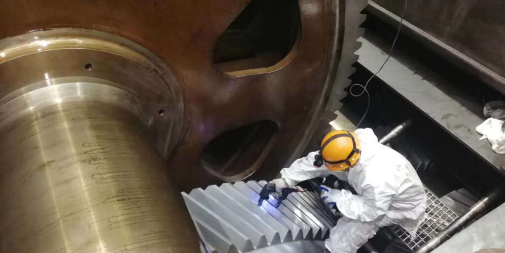
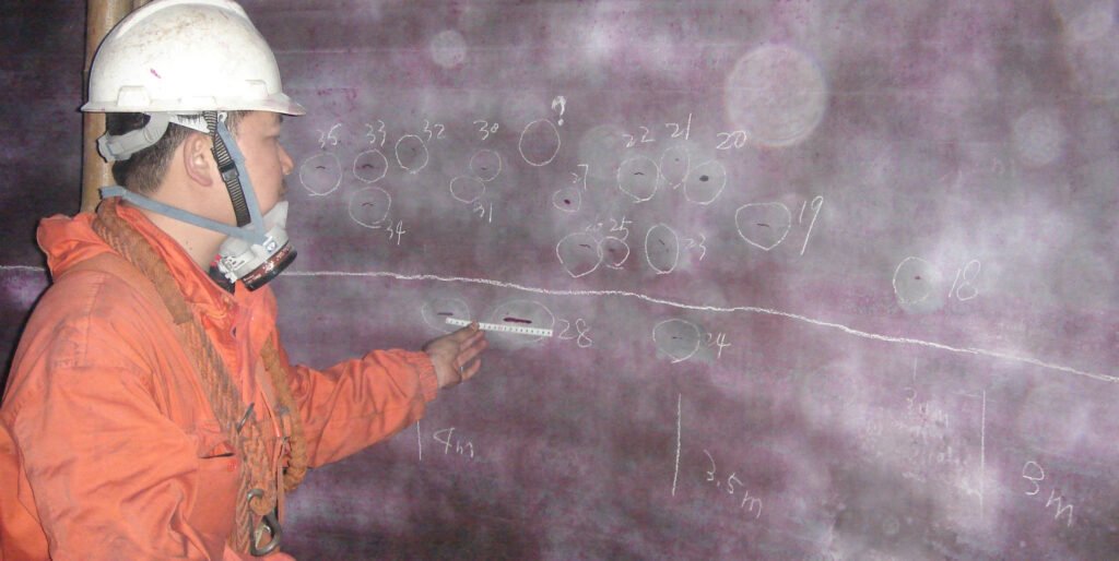
Portable testing uses miniaturized magnetic yokes, coils or battery-powered equipment, which is designed for on-site in-situ testing. Its core feature is strong flexibility and is not restricted by the site. The equipment usually weighs 5-15kg and can be carried to high altitudes, narrow spaces or outdoor operations, such as online inspection of the rotary kiln cylinder of a cement plant (without disassembly) and on-site sampling of vertical mill racks. Portable equipment combined with dry magnetic powder or spray-type wet magnetic suspension can quickly complete large-area scanning, which is especially suitable for regular equipment inspections and sudden fault troubleshooting. It is indispensable in ensuring the safe operation of large equipment (such as key components of a 10,000-ton cement production line).
Example: Magnetic Testing in the cement industry
In the cement industry, magnetic particle testing (MT) is often used in conjunction with penetrant testing (PT) to cover the defect detection needs of key equipment of different materials and ensure production continuity and safety.
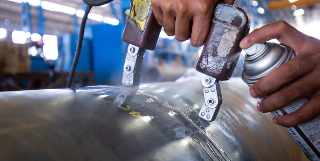
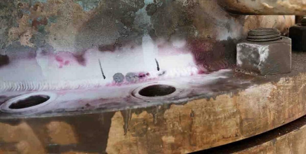
- For example, in large-scale cement production lines, the rotary kiln is the core calcining equipment, and the circumferential weld joints of its cylinder (carbon steel material) need to be checked for surface and near-surface welding cracks through magnetic particle testing - the weld is longitudinally magnetized using the magnetic yoke method, which can accurately identify fine cracks caused by high temperature stress; and for the austenitic stainless steel temperature measuring sleeve (non-ferromagnetic material) on the kiln body, penetrant testing is required for supplementary inspection to ensure that there are no open defects.
- In the inspection of ball mills, magnetic particle testing is mostly used for the journal surface of the main shaft (forged steel material), and a circumferential magnetic field is generated by the contact method to find axial fatigue cracks caused by long-term heavy loads;
- While the roller bearing seat (cast iron material) of the cement clinker vertical roller mill is combined with magnetic particle testing and penetrant testing, the former locates near-surface casting defects, and the latter checks surface pores. This "MT+PT" combination solution not only covers the key hidden dangers of a large number of ferromagnetic components in cement equipment, but also makes up for the limitations of magnetic particle testing for non-ferromagnetic materials. It strictly follows the cement industry equipment safety standards (such as GB/T 30574), avoids downtime accidents caused by equipment defects from the root, and ensures the stable operation of the production line.
Liquid Dye Penetrant Testing (DPI)
Liquid penetrant testing (PT) is a non-destructive testing method based on capillary action. It mainly uses specially formulated liquids to detect open defects on the surface of materials such as cracks, pores, pinholes, etc. It is suitable for almost all non-porous materials such as metals, ceramics, plastics, etc., especially for non-ferromagnetic materials that cannot be covered by magnetic particle testing, such as austenitic stainless steel and aluminum alloy. It has an irreplaceable role. The process involves applying the penetrant liquid to the surface of the test part, allowing it to penetrate into any surface-damaging defects, and then using a developer to absorb the penetrant liquid to form a visible discontinuity indication.
What is the primary objectives of PT in industrial applications
- Detect surface opening defects: Accurately identify open defects such as cracks, pores, pinholes, looseness, and incomplete penetration on the surface of the workpiece. These defects may become stress concentration points or medium leakage channels, affecting the safe operation of the equipment.
- Ensure the integrity of materials and components: By discovering potential defects, ensure that raw materials, semi-finished products and finished products will not fail due to the expansion of initial defects during subsequent processing, assembly or service. It is especially suitable for industrial parts that bear loads, high temperatures or corrosive environments (such as the surface of vertical mill rollers in cement machinery and the welds of rotary kilns).
- Verify manufacturing and processing quality: In the production link (such as casting, forging, welding, and heat treatment), check whether the process meets the standards, and promptly remove unqualified products to avoid defects from being transmitted with the production process, reducing the subsequent rework or scrapping costs.
- Support maintenance of in-service equipment: Regularly inspect the operating industrial equipment, and detect surface defects caused by fatigue, corrosion, wear, etc. at an early stage, provide a basis for maintenance decisions, and prevent production interruptions or safety accidents caused by sudden failures.
12 Advantages and Liquid Dye Penetrant Testing in NDT
- Widely Applicable Materials: Unrestricted by the material's magnetic properties, it can inspect all non-porous materials (metals, ceramics, plastics, etc.). It is particularly suitable for non-ferromagnetic materials (such as austenitic stainless steel, aluminum alloys, and copper alloys) that are not accessible with magnetic particle testing.
- Economical and Effective: Penetrant testing (PT) requires no complex or expensive equipment, is easy to operate, and is cost-effective.
- Widely Applicable Materials: Unrestricted by the material's magnetic properties, it can inspect all non-porous materials (metals, ceramics, plastics, etc.). It is particularly suitable for non-ferromagnetic materials that magnetic particle testing cannot reach (such as austenitic stainless steel, aluminum alloys, and copper alloys).
- High Sensitivity for Detecting Open Surface Defects: It can effectively identify fine surface cracks, pinholes, porosity, and incomplete weld penetration. Even cracks as small as microns in width can be clearly revealed through the coloring trace.
- Easy to Use and Low Equipment Cost: It does not require complex equipment. The core consumables are a coloring penetrant, a cleaning agent, and a developer (mostly in spray cans). It is highly portable and suitable for on-site inspections (such as field pipeline welds and spot checks of large equipment).
- Intuitive test results: defects are displayed as colored marks (usually red) that contrast sharply with the background. No special light source is required (natural light can be observed), and the inspector can directly determine the position, shape and size of the defect by naked eyes.
- Not limited by the shape of the workpiece: For parts with complex geometric shapes (such as curved surfaces, grooves, threads), the penetrant can penetrate all accessible surface defects through capillary action, and the detection range covers the entire surface of the workpiece.
- Clear defect indication: After the penetration process is completed, the defects are usually visible to the naked eye, which is convenient for direct interpretation and recording.
- Strong complementarity with other NDT methods: It is often used in conjunction with magnetic particle testing (MT), the former covers non-ferromagnetic materials, and the latter covers ferromagnetic materials, together to achieve comprehensive detection of surface defects of workpieces of different materials to meet diversified industrial needs.
- Portability: Penetrant testing (PT) equipment and materials are usually portable and can be used for on-site testing in various environments, including field conditions.
- Sensitivity to tiny defects: Penetrant testing (PT) can detect tiny surface defects that are not visible to the naked eye, including fine cracks, pores and other tiny defects.
- Batch inspection capability: Penetrant testing (PT) can efficiently inspect large numbers of parts in a single operation. By covering all accessible surfaces in one go, it is ideal for inspecting batches of small parts simultaneously. Sensitivity to small defects: Penetrant testing (PT) can detect small surface defects that are invisible to the naked eye, including hairline cracks, pores, and other microscopic defects.
9 Limitations of Liquid Dye Penetrant Testing in NDT
- Surface testing: PT can only detect open discontinuities on the surface. It is not effective for detecting defects below the surface.
- Unable to quantify defect size: Although it can display the surface morphology and location of defects, it is difficult to accurately measure quantitative parameters such as the depth and length of defects, and further evaluation is required in combination with other testing methods (such as ultrasonic testing).
- Affected by environmental factors: High temperature environment will cause the penetrant to evaporate too quickly, and low temperature environment will reduce the fluidity of the penetrant and affect the penetration effect; in addition, strong light or dust at the testing site may interfere with the observation of defect display and reduce the accuracy of interpretation.
- Limited by material porosity: It is not suitable for porous materials (such as wood, foam plastics, and some ceramics) because the penetrant will be absorbed by the pores of the material itself, resulting in serious background interference and inability to distinguish defects from the pores of the material itself.
- Health and safety issues: Some liquid penetrants, emulsifiers, and developers may cause skin irritation or other health problems. Appropriate safety precautions must be taken, including the use of personal protective equipment (PPE). Since the chemicals used in PT may cause harm to the environment and health, the handling and disposal of these chemicals also need to be carefully managed.
- High requirements for accessibility of defect locations: The penetrant needs to directly contact the defect opening. For deep holes, the bottom of narrow slits, or hidden surfaces of complex structures (such as deep grooves inside parts), if the penetrant cannot reach them, the defects in this area cannot be detected.
- Cleaning and condition requirements: Careful surface cleaning must be performed before and after testing to avoid contaminating the test results. Environmental factors such as high temperature or strong winds will have an adverse effect on the application and effectiveness of penetrants, so it is necessary to control environmental conditions to obtain accurate results.
- Potential impact of chemical reagents: Penetrants, cleaning agents, etc. are mostly organic solvents or chemical preparations, which may corrode or swell certain sensitive materials (such as some plastics and rubbers), and attention should be paid to the health protection and environmental protection of operators.
- Dependence on surface cleanliness: Oil stains, rust, oxide scale, coatings, etc. on the surface of the workpiece will hinder the penetration of the penetrant into the defects, and strict pretreatment (such as cleaning and polishing) is required, otherwise it is easy to cause missed detection and increase the preparation cost and time before testing.
How does Liquid Penetrant Testing Works? the working principle and mechanism
In breif: Liquid penetrant testing is based on capillary action. First, clean the surface of the workpiece, apply the penetrant to make it penetrate into the open defect; after removing the excess penetrant on the surface, apply the developer, and absorb the penetrant in the defect through reverse capillary action, forming an obvious trace. It can detect defects such as cracks on the surface of non-porous materials. It is easy to operate, the results are intuitive, and it is suitable for a variety of materials. following is the detail in steps:
What are the Steps in the Liquid Dye Penetrant Testing Process
- Surface pretreatment: Oil, scale, etc. need to be thoroughly removed, and the roughness usually needs to be ≤Ra 25μm, otherwise the pollutants will block the defects. For the rusted surface of cement equipment, mechanical grinding and solvent cleaning are often used to ensure that the penetrant can contact the defect opening.
- Application of penetrant: The penetrant needs to cover the entire surface, and the dwell time (penetration time) is set according to the size of the defect, generally 5-30 minutes. High-viscosity penetrants are suitable for rough surfaces, while low-viscosity ones are more permeable to fine cracks and can penetrate cracks as wide as 0.5μm.
- Removal of excess penetrant: The water-washable type needs to control the water pressure (≤0.2MPa) to avoid washing away the penetrant in the defect; the solvent-based type is wiped unidirectionally with a liquid-soaked cloth to prevent secondary contamination. The key is to retain the penetrant in the defect, relying on the capillary binding effect.
- Application of developer: The developer "sucks out" the penetrant in the defect through capillary action, and the dwell time is usually 5-10 minutes. Dry developer is suitable for rough surfaces, while wet developer can enhance the display of tiny defects, and the traces formed are 10-50 times larger than the actual defects.
- Detection and observation: The coloring method is observed under natural light of ≥500lux, and the fluorescence method needs to be observed under ultraviolet light (365nm). The fluorescence intensity in the dark is ≥1000μW/cm², and 0.1mm surface cracks can be identified.
- Post-processing: Residual developer and penetrant need to be removed to avoid corrosion of the workpiece. For food-grade equipment, it needs to be cleaned with a special solvent to meet hygiene standards.
Liquid Interaction with Materials mechanism:
Surface Tension
Surface tension is a phenomenon in which surface molecules on a liquid are attracted by molecules within it more strongly than by molecules outside it (air). This creates a tension along the surface that causes it to contract, causing the surface to exhibit properties similar to those of a stretched elastic film. The surface tension coefficient (unit: N/m) is used to express this tension. For example, the surface tension of water at 20°C is approximately 0.073 N/m. In penetrant testing, too low a surface tension can lead to excessive diffusion of the penetrant, while too high a surface tension can hinder penetration into tiny defects. Therefore, additives are needed to control the penetrant's surface tension, ensuring that it wets the workpiece surface and penetrates micron-sized cracks.
Capillary Action
Capillary action is the phenomenon by which liquids spontaneously rise or penetrate into confined spaces (such as microcracks and capillaries) due to the synergistic effect of surface tension and adhesion. This action is present throughout the core process of penetrant testing:
- Penetration Phase: Penetrants penetrate cracks wider than 0.1μm due to capillary forces. The penetration depth is inversely proportional to the crack width and the liquid viscosity.
- Development Phase: The developer "draws" the penetrant from the crack to the surface through reverse capillary forces, creating a magnified defect trace. This is driven by the affinity between the developer and penetrant and the surface tension difference.
- The efficiency of capillary action directly determines the sensitivity of micron-sized defect detection and is the core mechanism by which penetrant testing can identify micron-sized cracks.
Wetting Ability/Action
Wettability is the ability of a liquid to spread on a solid surface. It is determined by both the liquid's surface tension and the liquid-solid interfacial tension. It is often measured by the contact angle (the angle between the liquid and the solid surface): a contact angle of less than 90° indicates good wetting (e.g., penetrant spreading on a clean metal surface), while a contact angle of greater than 90° indicates poor wetting (e.g., penetrant clumping and droplet formation on an oily surface). During penetrant testing, the contact angle of the penetrant on the workpiece surface must be less than 30° to ensure it fully covers and penetrates all open defects. Therefore, surface pretreatment (removing oil, scale, and other impurities) is key to improving wetting.
4 PT Processing Methods explained:
Water-Washable Method:
The penetrant is pre-mixed with an emulsifier (such as a fatty acid soap). Excess penetrant can be removed directly from the surface by rinsing with water. The rinsing pressure should be controlled between 0.1-0.3 MPa (to avoid over-rinsing and loss of penetrant within defects). The water temperature should be 38±3°C. This method has a simple process (penetration → rinsing → imaging) and is suitable for batch inspection of workpieces with rough surfaces (such as castings). However, it is slightly less sensitive for fine defects (<0.5μm wide) because the emulsifier may prematurely penetrate into small cracks.
Post-Emulsification Oleophilic Method:
The penetrant does not contain an emulsifier. After penetration, an oil-based emulsifier (such as a mixture of mineral oil and surfactant) is applied. The emulsification time should be strictly controlled between 10-60 seconds (adjusted according to the surface roughness of the workpiece), followed by a water rinse. Its emulsifier only binds to the surface penetrant and does not penetrate defects. Its detection rate for cracks as small as 0.2μm is over 30% higher than Method A, making it suitable for high-precision inspections (such as aerospace parts). However, it is highly sensitive to operating time.
Solvent Removal:
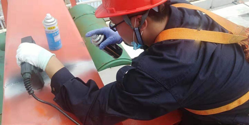
Excess penetrant is removed by wiping with a volatile solvent (such as ethanol or acetone). The solvent evaporation rate should be ≤ 2g/min (at 25°C) to avoid surface residue from excessive drying. This method does not require a water source and is suitable for localized on-site inspections (such as spot checks of cement kiln shell welds). However, the risk of secondary contamination of fine defects by the solvent is high, so a one-way wiping method should be used (avoiding reciprocating wiping).
Post-emulsification hydrophilic method:
Similar to Method B, but using a water-based emulsifier (containing a nonionic surfactant). After penetration, a pre-rinse at 30-50°C is performed (removing 60%-70% of the surface penetrant). Then, an emulsifier is applied to remove residual penetrant through a "detergency" action (a decontamination mechanism). The emulsifier concentration should be controlled between 5% and 10% (mass fraction), and the treatment time is 5-15 minutes. This method is 40% more efficient than Method B in removing excess penetrant from workpieces with complex geometries (such as around the oil hole of a vertical mill bearing seat), while also minimizing the impact of oil-based residue on subsequent processes.
3 Penetrant Types and Sensitivity Classifications for Liquid Penetrant Testing (PT)
The type of penetrant directly determines defect detection capabilities. Key differences lie in fluorescence characteristics, visibility, and sensitivity levels. Specific technical parameters and application scenarios are as follows:
Fluorescent penetrant (Type 1):
Contains fluorescent dyes (such as rhodamine B, sodium fluorescein), emits yellow-green fluorescence of 510-550nm under ultraviolet light (UV-A) with a wavelength of 320-400nm, and the fluorescence intensity must be ≥2000μW/cm² (380mm from the light source). Its sensitivity covers Level ½ to Level 4 (according to ISO 3452 standard):
- Level ½: can detect cracks with a width of ≥5μm, suitable for general industrial parts;
- Level 4: can identify micro cracks with a width of ≥0.5μm, used for key aerospace parts (such as turbine blade tenons).
- The signal-to-noise ratio of the fluorescent signal (defect fluorescence intensity / background fluorescence intensity) must be ≥3:1 to ensure that tiny traces can be identified. It is the preferred type for high-precision detection.
Colored penetrant (Type 2):
Contains red/purple dyes (such as Sudan red, azo dyes), visible under natural light (≥500lux), fixed sensitivity at Level 1, and can detect cracks ≥20μm wide. Its contrast (color difference between dye and developer background) must be ≥70% (CIE color difference value). Although its sensitivity is lower than that of the fluorescent type, it does not require a special light source and is suitable for rapid on-site inspections (such as the casting surface of cement machinery).
Dual-purpose penetrant (Type 3):
Contains both fluorescent dyes and colored dyes, which appear red under white light and fluorescent under ultraviolet light, but its sensitivity is lower than that of a single type: equivalent to Level 1 (cracks ≥30μm wide) in white light mode, and up to Level 2 (cracks ≥10μm wide) in fluorescent mode. Because it can adapt to different lighting environments without changing the penetrant, it is often used in complex sites (such as day/night alternating inspections), but a compromise in sensitivity must be accepted.
Sensitivity classification application principles:
- Level 1 (Type 2/3): Applicable to non-critical parts (such as automobile chassis bolts, cement equipment protective covers), with low detection cost and high efficiency;
- Level 2 and above (Type 1): Used for parts that bear alternating loads or high pressure (such as aircraft engine blades, high-pressure pipeline welds), among which Level 4 can meet the requirements of nuclear industry-level defect detection.
- Although Type 2/3 is called "low sensitivity", its detection ability is still much higher than visual inspection (visual inspection can only identify defects with a width of ≥100μm), which can cover the quality control needs of most industrial scenarios.
Liquid Penetrant Testing (PT) Removers and Emulsifiers Why it is needed?
Answer: Penetrant removal is a key step in the PT process. After the dwell time, the excess penetrant is removed from the surface using the appropriate solvent of emulsifier for the PT processing method used. The selection of removers and emulsifiers must match the penetrant type and treatment method (Method A-D). Their chemical composition and operating parameters directly affect the accuracy of defect detection.
Solvent Removers:
The main ingredients are petroleum fractions (such as kerosene derivatives), chlorinated solvents (such as 1,1,1-trichloroethane, which has been gradually replaced by environmentally friendly solvents) or water-based solvents (containing surfactants). The boiling point is usually 60-150℃, and the volatilization rate is controlled at 0.5-2g/min (25℃) to avoid excessive drying and causing penetrant residue. When used in Method C (solvent removal method), it is necessary to wipe in one direction with a lint-free cloth dipped in solvent, and the amount of solvent used per 100cm² wiping area is ≤5mL to prevent excessive solvent from penetrating into defects. Environmentally friendly solvents (such as limonene derivatives) must comply with the VOC limit of ≤50g/L (EU REACH standard) and are suitable for on-site random inspections (such as bolts for wind power equipment), but cracks with a width of less than 1μm may be missed due to solvent intrusion.
Lipophilic Emulsifiers:
It is an oil-based liquid (containing fatty acid esters and non-ionic surfactants). The difference in solubility parameter (δ) with the oil-based penetrant must be ≤2 (J/cm³)¹/² to ensure rapid emulsification. When used in Method B (post-emulsification lipophilic method), the emulsification time is strictly controlled at 30-180 seconds (depending on the roughness of the workpiece), and the emulsifier temperature is maintained at 15-50℃. The water flushing pressure after emulsification is 0.1-0.3MPa, and the flushing time is 20% shorter than Method A, which can reduce the flushing of the penetrant in the defect. Its emulsification efficiency (the amount of penetrant residue after emulsification) must be ≤5%, which is suitable for detecting precision parts (such as hydraulic valve blocks), but the cost is 30% higher than that of hydrophilic type.
Hydrophilic Emulsifiers:
It is a water-based concentrate (containing alkyl glycosides and amphoteric surfactants), the dilution ratio is usually 1:5 to 1:20 (water: emulsifier), and the pH value is controlled at 7-9. When applied to Method D (post-emulsification hydrophilic method), it is necessary to pre-rinse at 0.1MPa (remove 60% of the surface penetrant), then soak or spray the emulsifier, and remove the residue through the "decontamination-dispersion" dual mechanism. The emulsification time is 5-10 minutes. For workpieces with surface roughness Ra>12.5μm (such as castings), its removal efficiency is 40% higher than that of oleophilic type, and it is easy to biodegrade (BOD5/COD>0.3), suitable for batch testing (such as automobile wheels), but the emulsification ability will decrease by 25% at low temperature (<10℃).
Types of developers for liquid penetrant testing in nondestructive testing (NDT)
The developer is a key step in penetrant testing. It absorbs the penetrant in the defect to the surface through capillary action and amplifies the display. Its morphology and performance directly affect the sensitivity of defect detection. The specific technical characteristics are as follows:
Dry powder developer (Form A):
It is composed of ultra-fine adsorbent powder (such as magnesium oxide, silicon dioxide), with a particle size distribution controlled at 5-20μm (90% of particles <15μm), and a specific surface area ≥50m²/g, ensuring strong adsorption capacity. It is applied by spraying or dusting, and the developer thickness must be ≤0.1mm (controlled by a 45μm sieve), and the effect is best in a dry environment (relative humidity <60%). It is suitable for fluorescent and colored penetrants, especially for cracks with a width of ≥1μm, and can magnify the defect display by 5-10 times. It is easy to remove during post-processing (compressed air blowing is sufficient), but in a high humidity environment (>80%), powder agglomeration will cause background interference, which meets the "no fluorescent background" requirement in the ISO 3452-3 standard (fluorescent residue ≤10μW/cm²).
Water-soluble developer (Form B):
It is a solution of powder (such as sodium carbonate, organic acid salt) and water, with a concentration of 5%-15% (mass fraction) and a pH value of 7-9 to avoid corrosion of the workpiece. It is applied by dipping or spraying, and forms a uniform film (thickness 20-50μm) after drying, with a coverage rate of 100% for large-area workpieces (such as the inner wall of a storage tank). The solution stability must meet the requirement of no precipitation after 48 hours of standing, and the development time is 30% shorter than that of the dry powder type (usually 5-10 minutes). Because it does not contain suspended particles, there is no risk of scratching precision parts (such as bearing rollers), but the sensitivity is slightly lower than that of the dry powder type (cracks with a width of ≥3μm can be detected), which is suitable for batch assembly line detection.
Water suspension developer (Form C):
Made from inorganic powder (such as zinc oxide, calcium carbonate) suspended in water, with a solid content of 20%-40%. It needs to be kept suspended by continuous stirring (speed 50-100r/min), and the particle size is ≤30μm. It is applied by dipping or spraying, and forms a porous coating after drying. The capillary suction is 30% stronger than water-soluble, and cracks with a width of ≥2μm can be detected. The uniformity of coverage on curved workpieces (such as pipe elbows) is better than that of dry powder type, but the residual moisture may cause rust on cast iron parts, and post-processing (water washing or solvent wiping) must be completed within 1 hour after imaging.
Non-aqueous developer (Form D/E):
Developer particles (such as aluminum oxide) are suspended in volatile solvents (such as isopropanol, n-hexane), the boiling point of the solvent is 30-60℃, and it is ensured to dry within 30 seconds after spraying. The particle size distribution is 5-15μm and the solid content is 10%-20%. It is usually applied with aerosol spray cans, with a film thickness of 5-15μm, suitable for local detection (such as welding seam repair points) and on-site operations (water-free environment). Form D is a fluorescent enhancement type (containing brightener), and Form E is a coloring type (containing white pigment). The sensitivity of crack detection for width ≥1.5μm is close to that of dry powder type, but the solvent VOC content must be ≤100g/L (environmental protection standard), and the cost is 2-3 times that of water-based type.
Application of Penetrant Testing (PT) in the Cement Industry
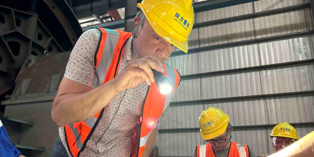
Liquid Penetrant Testing (PT) is a vital non-destructive testing (NDT) method used in the cement industry to detect surface-breaking flaws such as cracks, porosity, pinholes, and laps on metallic surfaces. Although the cement production environment is dominated by heavy machinery and high-wear components, many critical parts are subject to cyclic stresses, high temperatures, and mechanical loads—making surface integrity inspections essential.
Dye penetration test used in Vertical Roller Mill (VRM) – Grinding Rollers and Housings
- Inspection Focus: PT is used to inspect the surface of vrm cement mill grinding rollers, rocker arms, and mill housing weld joints.
- Common Defects: Fatigue cracks, surface fractures, and casting porosity caused by vibration, pressure, and abrasive wear.
- Maintenance Role: PT is applied during scheduled shutdowns to prevent roller failure and optimize component life.
Dye penetration test for Ball Mill – Shell, End Covers, and Welded Joints
- Inspection Focus: Shell plate weld seams, trunnion surfaces, and feed/discharge end covers.
- Common Defects: Surface cracks at welds and forged sections, particularly after long service in high-load conditions.
- Relevance: Surface defects in ball mills can lead to shell cracking or trunnion failure—PT allows early detection before structural issues arise.
Pt application in Rotary Kiln – Shell, Tyre Rims, and Girth Gear Welds
- Inspection Focus: Kiln shell longitudinal welds, tyre contact zones, girth gear connections, and shaft attachments.
- Common Defects: Heat-induced cracking, stress corrosion, weld defects, and mechanical fatigue.
- Importance: A minor surface crack at the shell or tyre interface, if undetected, can propagate under thermal cycling—PT is used during kiln shutdowns or after emergency stoppages to inspect these critical areas.
Radiographic Testing (RT)
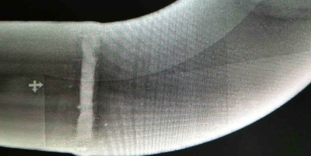
Radiographic Testing (RT) is a non-destructive testing technique that uses the attenuation properties of X-rays, gamma rays, etc. when penetrating matter. The principle is that when the radiation passes through the workpiece, the internal defects (such as cracks, pores, slag inclusions, etc.) and the matrix material have different absorption capabilities for the radiation, resulting in differences in the intensity of the transmitted radiation, and ultimately forming an image on the film or digital detector that reflects the shape and location of the defect. Just as doctors use X-rays to check for broken bones in patients, non-destructive testing (NDT) inspectors also use radiation testing to view defects inside components used in critical industrial applications. This technology is applicable to a wide range of materials, including metals, non-metals, etc., and the test results can be permanently recorded.
What are the primary objectives of RT in industrial applications?
- Detect hidden internal defects: Accurately identify defects such as cracks, pores, slag inclusions, incomplete penetration, and looseness inside the workpiece, locate internal structural discontinuities, and present internal porosity and manufacturing errors in an easy-to-interpret way.
- Evaluate the internal quality of materials: Verify the internal integrity of raw materials, castings, welds, etc. to ensure that they meet design and process requirements, such as detecting the internal fusion of pressure vessel welds to avoid leakage during operation.
- Monitor the status of in-service equipment: Regularly inspect industrial equipment (such as pipelines and boilers) that has been in operation for a long time to find internal defects caused by fatigue, corrosion, wear, etc., and provide a basis for equipment maintenance and life assessment.
- Ensure the safety of critical structures: In the fields of aerospace, nuclear industry, petrochemicals, etc., radiographic flaw detection is used to ensure that key components (such as engine blades and nuclear reactor pipelines) are free of fatal internal defects to prevent catastrophic accidents.
- Provide traceable inspection records: RT inspection generates permanent inspection records, including evidence of test sensitivity when using image quality indicators (IQI), and can provide digital records of the inspected objects for subsequent display. This data can be used for quality traceability, defect analysis, and subsequent inspection comparisons, meeting industry standards for quality documentation.
- Supporting process improvement: By analyzing the types and distribution of internal defects discovered during inspection, problems within the production process (such as welding and casting) can be inferred, providing data support for process optimization and improving overall product quality.
What are the Advantages of Radiographic Testing?
- It is applicable to a wide range of materials and is not limited by the conductivity, magnetism, and surface roughness of the workpiece. It can effectively detect metals (steel, aluminum, titanium alloys), non-metals (ceramics, composite materials), or dissimilar material joints (such as dissimilar steel welds).
- It can realize the overall detection of large areas or complex structures, such as continuous filming of long-distance pipeline girth welds, or panoramic imaging of complex castings such as engine cylinders, which can fully cover the detection area and reduce the risk of missed detection.
- Sensitivity: RT can detect subtle changes in thickness and density along the X-ray beam path with an accuracy of about 1%.
- Intuitive: RT can easily locate internal structural discontinuities through visual comparison with known geometric features of the test object. It can penetrate the surface of the workpiece and directly detect internal three-dimensional defects, including volume defects (such as pores, slag inclusions) and area defects (such as buried cracks and unfused), especially for the internal quality inspection of thick and large parts (such as large castings and thick-walled welds).
- Versatility: RT is suitable for most types of materials.
- Clarity: RT testing can visually present internal holes and manufacturing errors, and is easy to interpret.
- Records: RT testing can create a lasting record of the test. When using image quality indicators (IQI), they can show the sensitivity of the test and generate a digital record of the test object for later review.
- The test results are presented intuitively in the form of images. The shape, distribution pattern and relationship of the defects with the surrounding structure are clearly visible, which is convenient for technicians to judge the nature of the defects (such as the type of welding defects and the cause of casting defects), providing a direct basis for quality assessment.
- The test records are permanent, and film or digital images can be archived for a long time, which is convenient for subsequent quality traceability and defect development trend analysis (such as image comparison of regular inspections of in-service equipment), meeting the strict requirements for quality documents in aerospace, nuclear industry and other fields.
- The technology is mature and highly standardized. There are clear industry standards for the inspection process and defect assessment methods (such as ASME, JB/T 4730). The test results are objective and comparable, which is convenient for quality recognition between different institutions.
What are the disadventages limitations of Radiographic Testing?
- Radiation hazards exist, requiring specialized protective equipment and limiting the inspection area, increasing operating costs and site requirements.
- Cost: Radiographic testing (RT) is a relatively expensive nondestructive testing method. It also requires specialized facilities and equipment costs, especially the high-energy radiography equipment (such as accelerators) required for inspecting thick and large workpieces, which comes with significant maintenance costs.
- The detection rate of planar defects is affected by orientation. When the defect plane is nearly parallel to the radiation direction, it is easy to miss due to the small projected area.
- The inspection effect is limited on high-density materials or excessively thick workpieces, as image clarity may be reduced due to excessive radiation attenuation, making it difficult to identify small defects.
- The inspection speed is slow, requiring multiple steps such as radiation exposure and image processing, making it unsuitable for in-line inspection scenarios requiring rapid feedback.
- Complex Geometry: Using RT on samples with complex geometries is impractical.
- Defect Size: Very small defects can be difficult or impossible to detect. Isolated defects less than 2% of the total thickness are generally undetectable.
- Accessibility: Both sides of the object being inspected must be accessible.
- Discontinuity Direction: The location of defects relative to the radiation beam is critical. Some defects, such as thin layers, may be missed by radiography if they are perpendicular to the radiation path.
- Training and Experience: Radiographic testing (RT) requires highly trained and skilled personnel to perform correctly and safely. Therefore, RT training and certification are crucial.
- Safety: Due to the radiation hazards associated with RT, inspectors must be licensed by state and federal agencies.
- Interpretation of test results relies on the operator's expertise and experience, which can be subject to subjective judgment.
- Test results are not available in real time; they must wait for images to be generated and processed, making it difficult to adjust inspection strategies on the fly.
What is the working principle of Radiographic Testing?
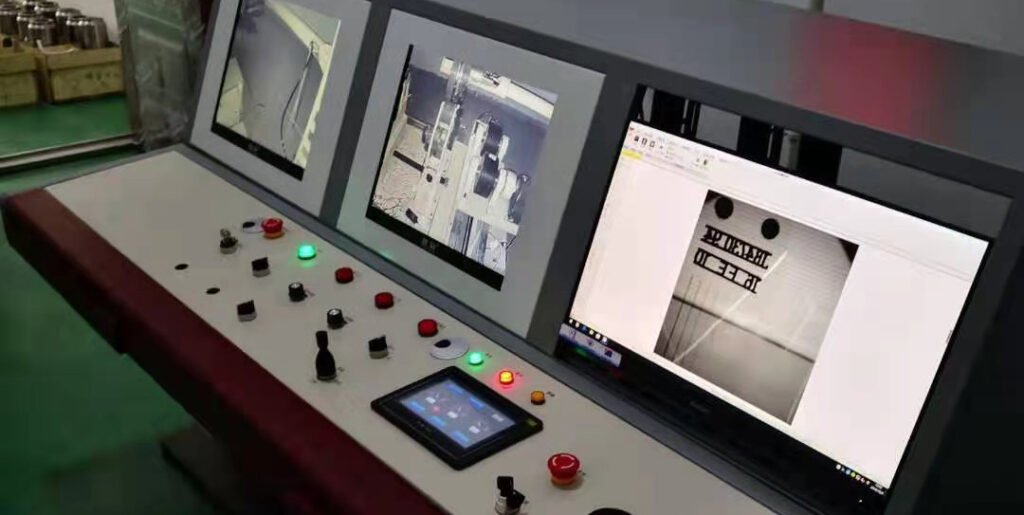
The principle of radiographic testing (RT) is to use penetrating rays such as X-rays and gamma rays. When passing through a workpiece, the internal material (including defects) has different absorption capacity for the rays, resulting in differences in the intensity of the rays. These differences are captured by detectors (such as film, digital flat panels) and formed into images. The defective area will show a different light and dark contrast from the normal area in the image due to its weak absorption of rays, thereby achieving non-destructive detection and identification of internal defects (such as pores, cracks, and slag inclusions) of the workpiece. First we have to introduce Atomic Interaction with Materials in order to understand the mechanism of RT in micro level:
Atomic Interaction with Materials
The microscopic interaction between matter and radiation is the essential basis of X-ray flaw detection, and atoms, as the basic units of matter, are the core carriers of this interaction.
Atoms
An atom consists of a nucleus (containing protons and neutrons) and orbiting electrons. The number of protons and electrons is equal to maintain electrical neutrality. The number of protons (atomic number Z) uniquely identifies an element, while the electrons outside the nucleus are arranged in energy levels. This structure directly influences a material's absorption properties of radiation. For example, the probability of the photoelectric effect is proportional to the cube of the atomic number Z, which explains the significant shielding properties of high-Z elements (such as lead).
Elements
An element is a pure substance composed of atoms of the same type. Its atomic number and electron arrangement together determine its ability to attenuate radiation of a specific energy. For example, the linear attenuation coefficients of iron (Z = 26) and lead (Z = 82) for 100 keV X-rays can differ by tens of times. Therefore, the elemental composition of a material is a key parameter in predicting radiation penetration depth and image contrast.
Isotopes
Isotopes are variations of the same element with the same number of protons but different numbers of neutrons. The ratio of neutrons to protons directly affects the stability of the nucleus. Stable isotopes of light elements (such as carbon and oxygen) typically maintain a 1:1 proton-neutron ratio, while heavy elements (such as uranium) require more neutrons to maintain equilibrium. This difference in the stability of nuclides provides a basis for the selection of radiation sources.
Radioisotopes
Radioisotopes, due to their unstable nuclei (e.g., excess neutrons or protons), release energy (alpha, beta, and gamma rays) through radioactive decay to stabilize. For example, Co-60 (cobalt-60), which is commonly used in industrial flaw detection, releases 1.17MeV and 1.33MeV γ rays through β decay, and Ir-192 (iridium-192) decays to release γ rays with an average energy of 0.38MeV. The interaction between these high-energy rays and matter (photoelectric effect, Compton scattering, etc.) is the microscopic mechanism for the formation of defect images in X-ray flaw detection.
Radiation Types in Radiographic Testing (RT)
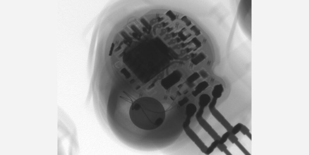
When radioactive atoms decay, they release a variety of radiation types, each interacting with matter in different ways. In RT, gamma rays and X-rays are the core radiation types due to their high energy and strong penetrating power.
X-rays (X-ray Radiation)
X-rays are generated by X-ray tubes: electrons are accelerated to high speeds (up to 50% of the speed of light) through a high-voltage electric field, and then hit a tungsten target (atomic number 74). About 1% of the electron's kinetic energy is converted into X-ray photons, and the rest is converted into heat energy. Its energy can be adjusted by the tube voltage (kV) (usually ranging from 20-450kV, and high-energy equipment can reach tens of MeV), and its intensity is controlled by the tube current (mA) and exposure time. This adjustability makes it suitable for workpieces of different thicknesses (such as 20kV for detecting thin aluminum parts, 450kV can penetrate 50mm thick steel), and the image contrast can be optimized by energy adjustment (high-energy rays have strong penetration and are suitable for thick parts; low-energy rays have large attenuation differences and are suitable for thin part defect detection).
Gamma Ray Radiation
Gamma rays are high-energy photons (electromagnetic radiation) released when unstable isotope nuclei decay. Their energy is determined by the type of isotope (e.g. Co-60 releases 1.17MeV and 1.33MeV gamma rays, Cs-137 releases 0.662MeV gamma rays), and their intensity decays exponentially over time (following the half-life characteristics, such as Co-60 half-life of 5.27 years). Gamma rays have strong penetrating power (slightly higher than X-rays at the same energy) and do not require power, making them suitable for field or large equipment (such as long-distance pipeline) inspections. However, their energy cannot be adjusted, and isotopes must be selected according to the thickness of the workpiece (e.g. Ir-192 is used for 20-100mm steel parts, Co-60 is used for 50-300mm steel parts), and higher protection requirements (because the photon energy is fixed, thicker lead shielding is required).
Introduction of Exposure Devices and Radiation Sources In RT
Radiographic inspection requires specific equipment to generate radiation and record the distribution of radiation after penetrating the workpiece. Traditionally, film is used as the imaging medium. With the development of technology, digital radiography (DR) and computer radiography (CR) technology have been widely used in industrial inspection. Regardless of the imaging method used, the operation process of non-destructive testing personnel includes: aiming X-rays or isotope radiation at the workpiece to be inspected, placing film or digital sensors on the other side of the workpiece, allowing the radiation to penetrate the workpiece and irradiate the sensor for a set time, then processing the film or sensor, and finally analyzing the generated image. There are differences in the generation and operation processes of different radiation sources.
X-ray Sources
- It needs to rely on electricity to drive, and the core equipment is the X-ray tube: the tube voltage is provided by the high-voltage generator (20-450kV conventional range, high-energy equipment can reach several MeV), and the electrons are accelerated to hit the anode target (such as tungsten target) to produce X-rays.
- The tube voltage (control of ray energy), tube current (control of ray intensity) and exposure time can be adjusted to adapt to the detection of workpieces of different materials and thicknesses - for example, 20-50kV is required to detect 10mm thick aluminum alloy, and 150-250kV is required to detect 50mm thick steel.
- The equipment is large in size (including high-voltage generator and cooling system), but the radiation can be terminated immediately by power off, and the safety is easy to control, which is suitable for batch detection in fixed places (such as workshops).
Gamma Ray Sources
- Gamma rays are generated by small particles of radioactive isotopes (such as Co-60, Ir-192, and Cs-137), encapsulated in a lead shielding container (such as the head of a flaw detector), and release gamma rays through decay without the need for external power.
- The energy of the ray is determined by the type of isotope (such as the average energy of Ir-192 is 0.38MeV, and Co-60 is 1.25MeV), and the intensity decays with the half-life (such as the half-life of Co-60 is 5.27 years). It needs to be selected according to the thickness and material of the workpiece - for example, Ir-192 is often used to detect 20-100mm steel parts, and Co-60 is selected for 50-300mm steel parts.
- The equipment is highly portable (can be made into a portable type), suitable for outdoor, high-altitude and other power-free scenarios (such as on-site inspection of pipeline welds), but the radiation cannot be turned off immediately, and the shielding and operating distance must be strictly controlled.
4 Radiographic Testing Techniques Used in NDT
Introduce 4 techniques used to detect and measure internal defects in materials. These techniques are classified according to the radiation introduction method, imaging mode and degree of advancement. The core goal is to improve the defect detection rate and measurement accuracy.
Film Radiography
- The most traditional imaging technology uses radiographic film as the imaging medium, and forms a latent image by absorbing the radiation that penetrates the workpiece.
- An image quality meter (IQI) is required during inspection to verify whether the quality of the radiograph meets the standard requirements (such as contrast and clarity).
- The film needs to be developed and fixed in a darkroom to present the image. The process is cumbersome, but the image resolution is high (up to 5-10 line pairs/mm), and it has long been the industry benchmark method.
- It is suitable for scenarios with high requirements for detection accuracy and long-term archiving (such as nuclear industry component inspection).
Computed Radiography (CR)
- Reusable phosphor plates (or cassettes) are used instead of film. The plates contain light-stimulated phosphors that can store the absorbed radiation energy in the form of latent images.
- The stored energy is released by laser scanning of the phosphor plates, which is converted into electrical signals and processed to generate digital images, which can be viewed on high-resolution displays.
- As a transitional technology between film radiography and digital radiography, it takes into account the flexibility of film and the processability of digital technology. The imaging speed is faster than film, but slower than digital radiography.
- It is suitable for scenarios where digital archiving is required but the equipment budget is limited. It is widely used in pressure vessel and pipeline inspection.
Digital Radiography (DR)
- Direct imaging is performed using a fixed flat-panel detector (digital detector array). The detector can convert the radiation energy into electric charge and then into a digital image.
- After the electrical signal is transmitted to the processor, a digital file is generated immediately. The imaging speed is close to real-time, which is much faster than CR (usually the image can be displayed within a few seconds).
- There is no need for film processing. The contrast can be adjusted and the details can be magnified in real time through software, which facilitates the rapid identification and analysis of defects.
- It is suitable for online inspection, batch workpiece inspection (such as automotive parts) and scenarios that require instant feedback. The inspection efficiency is significantly higher than traditional methods.
Computed Tomography (CT)
- Using a detector similar to digital radiography, multiple radiation exposures at different angles are performed to obtain cross-sectional images of the workpiece.
- Computer algorithms are used to reconstruct multi-angle images to generate three-dimensional images of the internal structure of the workpiece, which can realize the three-dimensional positioning and size measurement (such as depth and volume) of defects.
- It can clearly present the internal spatial distribution of complex structures (such as engine cylinders and composite components) and solve the overlapping interference problem of traditional two-dimensional images.
- It is suitable for high-precision three-dimensional defect analysis and is widely used in aerospace, precision manufacturing and other fields, but the equipment cost is high and the detection time is long.
Application of Radiographic Testing (RT) in Cement Equipment Manufacturing
Vertical Roller Mill (VRM): Radiographic Testing in Load-Bearing Weld Structures
Radiographic Testing is applied during the fabrication of VRM components to ensure the integrity of structural welds that bear grinding pressure and dynamic loads. Key applications include:
- RT inspection of multi-pass welds on the mill housing, pressure frame, and separator body, where internal defects like slag inclusions or lack of fusion can lead to structural failure under load.
- Examination of cast rocker arms and grinding rollers, where internal porosity or shrinkage cavities must be detected before final machining or assembly.
- RT ensures these critical components meet high fatigue-resistance standards, preventing in-service cracking under high-pressure grinding conditions.
Ball Mill: RT for Shell Seam Welds and Trunnion Attachments
Ball mill shells are composed of thick steel plates joined by full-penetration butt welds, and the end trunnions are typically welded or integrated into the assembly. Radiographic Testing is used to:
- Inspect longitudinal and circumferential seam welds of the shell, where internal flaws like incomplete penetration can propagate under torsional stress.
- Verify welds at trunnion-to-shell interfaces, which are critical load-transfer points subject to bending moments and bearing misalignments.
- Evaluate repair welds or shell section replacements in used or refurbished mills, ensuring structural compliance before recommissioning.
Rotary Kiln: RT for Shell Section Welds and Girth Gear Interfaces
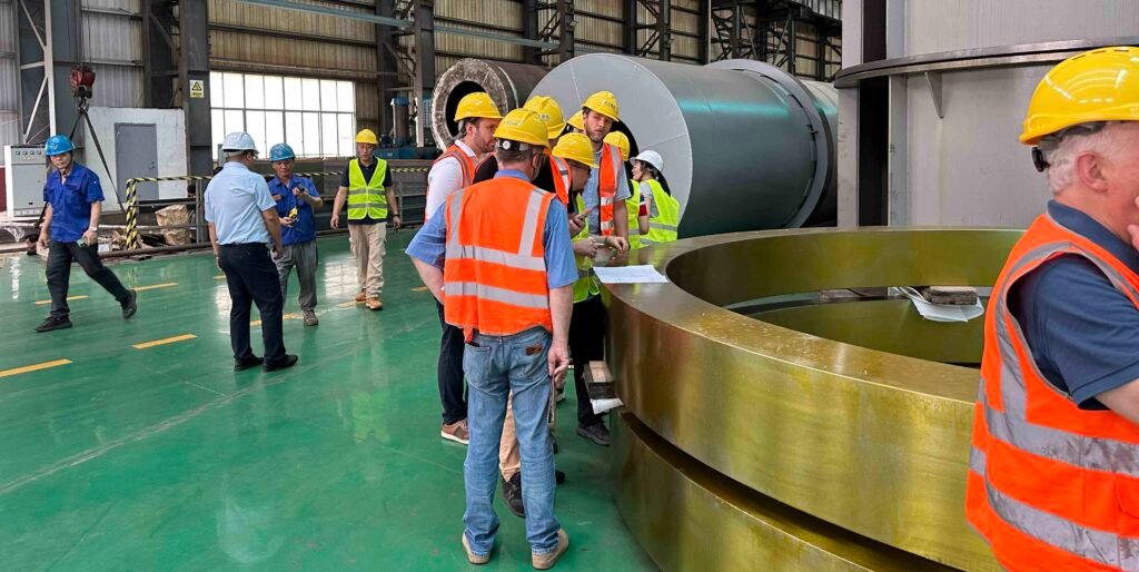
Rotary kilns, often over 100 meters in length, demand flawless fabrication of their cylindrical shells and mechanical couplings. Radiographic Testing is essential for:
- Inspecting full-penetration welds along the kiln shell’s longitudinal and girth joints, especially in the high-temperature burning zone.
- Evaluating girth gear weldments, where volumetric flaws could compromise torque transmission and alignment.
- Testing welds around tyre support rings and stiffener plates, where thermal cycling and mechanical expansion can induce fatigue cracking—RT ensures long-term shell reliability and prevents unplanned kiln shutdowns.
Ultrasonic Testing (UT)

Now we are going to introduce UT, which is probably the most common used inspection method in our factory. Ultrasonic testing is a technology that uses the propagation characteristics of high-frequency sound waves 0.5-25MHz in materials to achieve non-destructive testing. Sound waves are emitted to the equipment through a probe. When the sound waves encounter internal defects (such as cracks, pores) or interfaces, a reflected signal is generated. The defect location and nature can be determined through conversion analysis. High-frequency sound waves are used to detect and measure discontinuities in industrial components. In the cement industry, this technology is widely used in key equipment such as ball mills (to detect cracks in the welds between the hollow shaft and the cylinder, and loose liner bolts), vertical mills (to check fatigue cracks in the roller journal, and internal defects in the reducer gearbox), and rotary kilns (to detect contact fatigue cracks between the wheel belt and the supporting roller, and defects in the cylinder circumferential seam welding). It can accurately identify internal hidden dangers that affect operational safety without disassembling the equipment, thereby ensuring production continuity.
What are the primary focus of utrasonic testing?
- Thickness Measurement: By comparing ultrasonic echoes reflected from the equipment's surface and interior, the system accurately measures the wall thickness of key components such as ball mill cylinders and rotary kiln bodies. This system monitors thickness reduction caused by long-term wear and corrosion, preventing equipment leakage or structural failure due to insufficient wall thickness.
- Internal Defect Detection: Utilizing ultrasonic reflection signals at defect locations, the system identifies hidden defects such as cracks in ball mill hollow shaft welds, inclusions within vertical mill rollers, and fatigue cracks in rotary kiln tyres. If not detected promptly, these defects can expand under heavy loads and high temperatures, leading to equipment downtime or accidents.
- Stress Detection: The system measures the preload stress of bolted connections in cement machinery (such as the vertical mill liner fixing bolts) and residual stress in components (such as the internal stress after welding in rotary kiln cylinders). This ensures bolts are properly tightened, prevents deformation or fracture caused by stress concentration, and ensures stable equipment operation.
- Evaluate weld quality and detect defects such as incomplete penetration, lack of fusion, and weld overhangs in welded joints.
- Inspect the internal integrity of forgings and castings, identifying process defects such as forging folds and casting shrinkage cavities.
- Detect interfacial defects such as delamination and delamination between composite layers.
- Evaluate fatigue cracks or stress corrosion cracks in components such as bolts and shafts.
- Measure acoustic properties of materials (such as sound velocity and attenuation coefficient) to indirectly reflect changes in material properties.
- Evaluate the stress state of critical structures, such as residual stress and bolt preload.
- Verify the manufacturing process conformity of materials or components to ensure product compliance.
What are the adventages of ultrasonic flaw testing
- It can measure the thickness of components and has both detection and thickness monitoring functions, which RT and PT do not have.
- Safety: Unlike radiographic testing (RT), the ultrasonic waves used by UT are harmless to personnel in the detection area, do not require the use of radioactive sources, have no radiation hazards, are more friendly to detection personnel and the environment, and eliminate radiation safety hazards.
- Sensitivity: UT is highly sensitive to key defects that affect structural integrity (especially planar defects).
- It has a large detection depth and is suitable for thick-walled components (such as ball mill barrels and rotary kiln bodies in cement machinery), while PT can only detect surface opening defects and RT has low detection efficiency for thick parts.
- The equipment is highly portable, and the small UT probe can penetrate into complex structures (such as the narrow cavity of a vertical mill). RT equipment is bulky and PT is limited by surface accessibility.
- Versatility: UT can detect surface, near-surface and near-surface defects, and is suitable for a variety of applications.
- Portability: UT equipment is easy to carry and can be used for detection in various environments and locations.
- Speed: UT delivers rapid inspection results, supporting time-sensitive projects.
- Defect Assessment: Advanced UT technology helps inspectors determine defect size and severity, supporting informed decision-making.
- It has high sensitivity for detecting internal defects, particularly linear defects (such as cracks), and can precisely locate defect depth and planar dimensions.
- It is safe to operate, requiring no radioactive sources and no radiation hazards, making it more user- and environmentally friendly (RT poses radiation risks and requires strict safety precautions).
- It offers fast inspection speeds and real-time results, making it suitable for on-site, online testing (such as non-stop spot checks of equipment in cement production lines). RT requires film processing and is time-consuming.
- It is applicable to a wide range of materials, including metals, non-metals (such as wear-resistant ceramic liners in cement machinery), and composite materials. PT is only suitable for smooth, non-porous materials.
- It offers more accurate quantitative analysis of defects (such as calculating defect equivalents based on echo amplitude). PT only reveals surface traces of defects and is difficult to quantify.
What are the limitations of ultrasonic flaw detection
- High skill requirements for inspectors, who need to be proficient in interpreting waveform signals, and defect characterization (such as distinguishing cracks from inclusions) relies on experience, which is easy for novices to misjudge; PT/MT results are intuitive (visible color traces), and RT film can visually observe the defect morphology.
- Sensitive to surface roughness, rough surfaces will cause disordered sound wave reflection, and pretreatment (such as polishing) is required, otherwise the detection accuracy will be affected; although PT also requires surface cleaning, it has a higher tolerance for roughness.
- Complex geometry: It can be challenging to use ultrasonic testing (UT) to detect parts with irregular shapes or complex geometries.
- Requires coupling agent: A gel or liquid medium is required to provide an interface between the probe and the material, which can be a logistical challenge in some cases.
- The equipment cost is high, especially the high-precision digital UT instrument is significantly more expensive than the chemical reagents and tools of PT/MT; although RT equipment is more expensive, the cost-effectiveness of small UT equipment is still lower than that of basic PT/MT.
- It cannot provide an intuitive image record of defects, and needs to rely on waveform data and report descriptions. Traceability is not as clear as RT film or PT/MT defect photos.
- Material properties: Ultrasonic testing may be less effective for materials that scatter or absorb sound (such as concrete or stainless steel castings), or inelastic materials (such as rubber and soft plastics).
- Discontinuity direction: Discontinuities in certain directions may pose detection challenges and require testing using other methods.
- Training and experience: Ultrasonic testing requires a high level of expertise. Technicians need to be familiar with physics and have confidence in their ability to analyze data and interpret results. Therefore, ultrasonic training and certification are essential.
- It is difficult to detect blind spots in complex-shaped components, such as curved surfaces and corners, where sound waves are easily scattered and may be missed; RT can cover complex structures through multi-angle transillumination, and PT/MT is more adaptable to the detection of curved surface defects.
- The detection effect on non-metallic materials (such as rubber gaskets and plastic parts in cement machinery) is limited because these materials have large sound wave attenuation and weak signals; PT is still effective for non-porous non-metallic surface defects.
- It has low sensitivity for certain types of defects, such as tiny pores and loose volume defects, as their reflected signals are weak and easily overlooked. RT has higher sensitivity for detecting volume defects.
What is the working principle of ultrasonic testing?
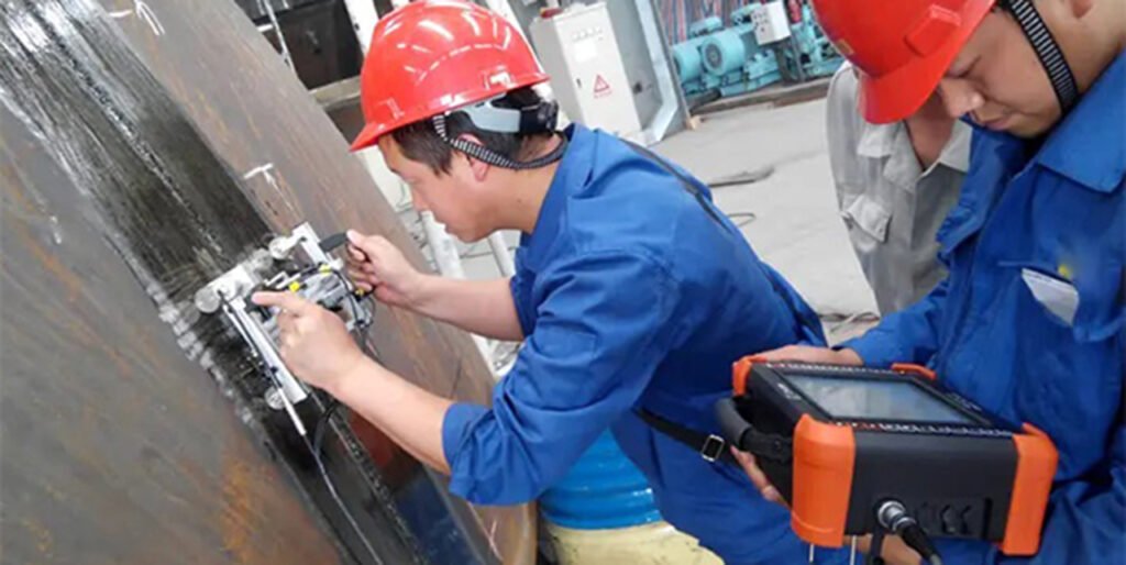
The working principle of ultrasonic testing (UT) is as follows: a probe converts electrical pulses into high-frequency ultrasonic waves, which are then transmitted through a coupling agent into the component being tested. When the sound waves encounter internal defects or material interfaces, they are reflected. The reflected waves are received by the probe and converted into electrical signals, which are displayed on the instrument. Technicians analyze the echo's duration (determining the defect's depth) and amplitude (determining the defect's size) to identify the defect type. Different wave types (such as longitudinal and shear waves) and probe types can meet different testing needs, allowing internal quality assessment to be completed without damaging the workpiece.
Principle of Sound Wave Interaction with Materials
The sound waves used in industrial ultrasonic testing (UT) are ultrasonic waves, whose frequency far exceeds the human hearing range (usually more than 1MHz), and the high-frequency characteristics ensure the accuracy of the detection. When ultrasonic waves penetrate the material, they interact with internal discontinuities (such as cracks, pores, inclusions) and reflect back to the transducer. Ultrasonic testing is based on the reflection, refraction and penetration principles of sound waves to achieve accurate positioning and identification of discontinuities inside the material.
Reflection
Similar to the principle of light reflection off a mirror, sound waves reflect when they encounter a material boundary (such as the interface between a workpiece surface and air) or an internal discontinuity. The strength of the reflection depends on the difference in acoustic impedance between the two media (acoustic impedance = density × speed of sound). The greater the difference, the stronger the reflected signal. For example, pores within metal produce distinct reflection echoes due to the significant difference in acoustic impedance with the metal, which is the core basis for defect detection in ultrasonic testing.
Refraction
Similar to the way a straw appears to bend in water, when a sound wave is not incident perpendicularly at the interface between two media, its propagation direction changes. This phenomenon is called refraction and is governed by Snell’s law: sinθ₁/sinθ₂ = c₁/c₂ (where θ₁ is the angle of incidence, θ₂ is the angle of refraction, and c₁ and c₂ are the speeds of sound in the two media, respectively). In industrial inspection, angled probes are often used to refract sound waves into shear waves, avoiding surface blind spots and more effectively detecting internal defects in structures such as welds.
Penetration
Similar to light penetrating glass, sound waves can penetrate materials and propagate inward, transferring energy to deeper layers of the medium. Penetration is primarily determined by the material's acoustic attenuation properties: the lower the material's absorption and scattering of sound waves (lower attenuation coefficient), the greater the sound wave's penetration depth. For example, steel exhibits low acoustic attenuation, allowing ultrasonic waves to penetrate workpieces tens of centimeters or even thicker. However, porous materials (such as certain composite materials) experience significant scattering, significantly limiting the effective penetration distance of sound waves.
What are the 4 Wave Modes in UT
Longitudinal waves (L-mode)
- Particle vibration aligns with the direction of wave propagation. These waves are the fastest propagating ultrasonic wave mode (e.g., approximately 5900 m/s in steel) and have the longest wavelength.
- They can propagate in solids, liquids, and gases, exhibiting slow energy decay. They are suitable for detecting internal defects in homogeneous materials such as plates and forgings (e.g., shrinkage cavities and inclusions in forgings), and are the most commonly used basic wave mode in industrial inspection.
Lamb waves
- Similar to surface waves, they primarily propagate in thin plates (thickness comparable to the wavelength) or composite laminates. The particle vibration patterns are complex (including both symmetric and asymmetric types).
- The long transmission distance (up to several meters) makes it suitable for detecting delamination and corrosion (such as thinning of boiler water-cooled wall tubes) of large-area thin plates or interlayer delamination of composite materials through "pitch-catch" technology, which is much more efficient than traditional point-by-point inspection.
Shear waves (T-mode)
- The vibration direction of the particles is perpendicular to the propagation direction of the wave, and the propagation speed is about 1/2 of the longitudinal wave (about 3200m/s in steel). It can only propagate in solids (liquids and gases cannot withstand shear force).
- It is extremely sensitive to linear defects (such as cracks and lack of fusion). After being refracted and excited by the oblique probe, it can avoid the blind area on the surface of the workpiece and is widely used in weld detection (such as the groove lack of fusion detection of the pipe girth weld).
Surface waves (Rayleigh Waves)
- The particles vibrate in an elliptical trajectory, and the energy is concentrated in a depth range of about one wavelength below the surface of the material, and only propagates along the surface.
- It has a very high detection rate for surface and near-surface defects (such as surface cracks of shaft parts and surface folding of forgings), and is suitable for detecting the surface quality of large components (such as the journal surface of the turbine rotor).
2 working modes of ultrasonic testing (UT Testing Modes)
Ultrasonic testing emits sound waves through a transducer (made of piezoelectric material that can convert electrical pulses into sound waves). The tester uses an ultrasonic instrument to trigger electrical pulses and transmit sound waves to the material through the transducer in two modes.
Pulse-Echo Mode
- Uses a single transducer to both transmit and receive sound waves: the transducer first emits an ultrasonic pulse, which propagates through the material. Upon encountering a defect or bottom surface, the sound wave is reflected. The reflected echo is received by the same transducer and converted into an electrical signal.
- Defects are identified by analyzing the echo's amplitude (which reflects defect size; higher amplitudes generally indicate more significant defects) and location (depth calculated based on propagation time). For example, a normal workpiece will show a bottom echo; an abnormal echo preceding the bottom echo indicates an internal defect.
- The advantage is that transducers are not required on both sides of the workpiece. This makes it suitable for applications where only one side is accessible (such as inspecting the inner wall of a pipe or the exterior of a large container). It is the most commonly used mode in industry.
Through-Transmission Mode
- Uses two transducers working together: one acts as a transmitter to transmit sound waves, and the other acts as a receiver to receive signals on the other side of the workpiece. When a defect exists within a material, the acoustic wave propagation path is blocked, causing the signal received by the receiving transducer to be partially attenuated (for smaller defects) or completely eliminated (for larger defects), thereby confirming the presence of a defect.
- This method is suitable for inspecting thin materials (such as thin plates and composite laminates) or components that are difficult to access from one side. However, it requires precise alignment of the transmitting and receiving transducers, and its defect location accuracy is lower than that of the pulse reflection method.
Three Ultrasonic Testing Data Display Methods (UT Data Display)
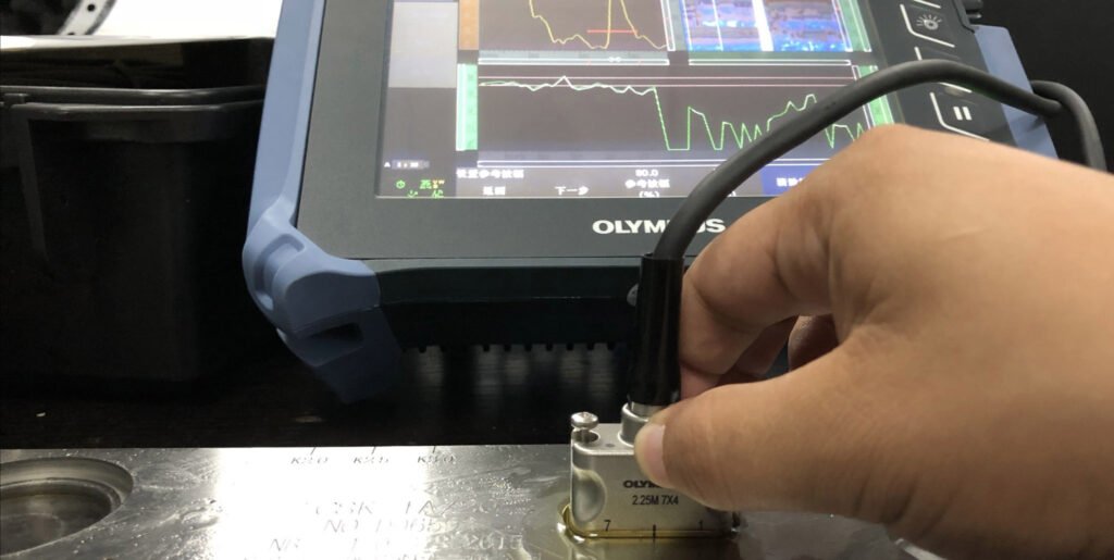
A-scan
Displays data in an X-Y coordinate graph: the horizontal axis represents the time of sound wave propagation and return (corresponding to the defect depth, based on the conversion of "depth = sound speed × time / 2"), and the vertical axis represents the echo energy (amplitude).
In the image, the baseline is the time axis, the echo of the bottom surface of the workpiece is usually the strongest signal (bottom wave), and the defect echo is the pulse signal before the bottom wave. Technicians judge the defect depth by the pulse position and evaluate the defect equivalent by the amplitude (such as comparison with the standard reflector). It is the most basic waveform display mode and is widely used for defect qualitative and quantitative analysis.
B-scan
Presents the detection results in a two-dimensional cross-sectional image: the horizontal axis is the probe movement distance (representing the surface position of the workpiece), the vertical axis is the sound wave propagation depth (corresponding to the time axis of the A-scan), and the echo intensity is reflected by grayscale or color differences. It can intuitively display the distribution of defects in the cross section of the workpiece (such as the length and depth extension range), help inspectors determine the three-dimensional contour of the defect (such as the inclination angle and extension direction of the crack), and is suitable for large-area scanning of plates and forgings to enhance the understanding of the spatial distribution of defects.
C-scan
Displays data in a top-down plan view: the horizontal and vertical axes represent the X and Y coordinates of the workpiece surface (corresponding to the plane position scanned by the probe), respectively, and the amplitude or time of the echo signal is encoded by color or grayscale to form an image consistent with the projection of the workpiece surface. It can accurately locate the projection position and plane size of the defect on the surface (such as the diameter of the pore and the length of the crack), and is often combined with the defect depth data to generate a three-dimensional model. It is suitable for scenes requiring precise positioning (such as precision detection of aerospace components), and is convenient for automated detection and data archiving of batch workpieces.
3 Common Ultrasonic Testing Techniques Used in NDT
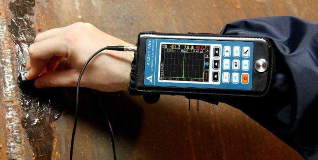
Ultrasonic testing (UT) uses a variety of technologies to detect and measure internal defects in materials. These technologies are classified according to the different methods of introducing sound waves, wave types and advanced methods. The core goal is to improve the efficiency of defect detection and measurement accuracy. The main technical application methods include the following three categories:
Air-Coupled Testing
- Using air as the coupling medium, a high-frequency transducer (usually 100kHz-2MHz) is used to transmit sound waves. No coupling agent is required, and it is a non-contact test.
- This method is suitable for materials that are not suitable for contact or immersion in water, such as porous materials (foam plastics), composite materials (carbon fiber laminates), paper, and textiles. It can detect interlayer delamination and delamination defects.
- Because air attenuates sound waves significantly (high-frequency attenuation is more pronounced), a lower frequency and optimized signal processing are required. While detection sensitivity is slightly lower than contact detection, it is more sensitive to rough or delicate materials.
Immersion Testing
- It is carried out in a water tank or water circulation system. The probe and the workpiece are not in direct contact. Water is used as a coupling medium to transmit sound waves (waterproof probe or focusing through an acoustic lens).
- It is suitable for automated inspection of batches of small parts (such as bolts, small forgings) or parts of complex shapes. The probe can be controlled by a robotic arm to scan at multiple angles to ensure inspection coverage.
- The advantage is that the acoustic wave coupling is stable (avoiding the influence of uneven contact pressure), which is suitable for materials with high surface accuracy requirements (such as aluminum alloy sheets for aerospace), but the equipment is large and limited by the size of the workpiece.
Contact Testing
- Straight Beam Testing: The probe directly contacts the surface of the material to be tested (conducting sound waves through coupling agents), and emits longitudinal waves vertically. It is suitable for detecting internal volume defects such as plates and forgings (such as pores and shrinkage holes). The integrity of the material can be judged by the attenuation of the bottom wave.
- Angle Beam Testing: The probe refracts the sound waves into transverse waves at a specific angle (commonly used 45°, 60°, 70°) through a wedge (such as a plexiglass wedge) to avoid the surface blind area. It is specially used for weld detection (such as pipeline girth welds, pressure vessel butt welds), which can effectively detect linear defects such as incomplete penetration and lack of fusion.
- Surface Wave Testing: Surface waves (Rayleigh waves) are excited by special probes and propagate along the surface of the material. They are highly sensitive to surface and near-surface cracks (such as fatigue cracks in shaft parts) and are suitable for detecting open defects on smooth surfaces.
UT application in cement machinery industry
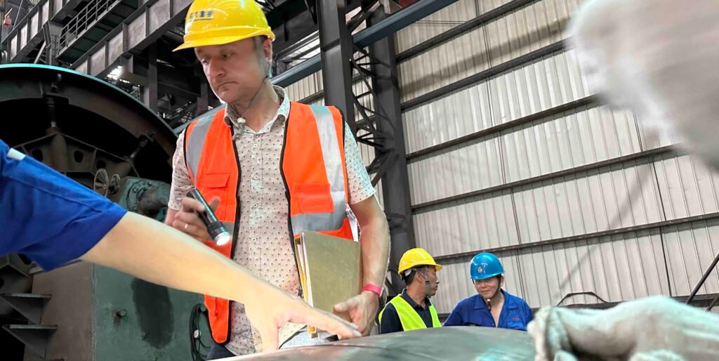
Rotary Kiln System ultradonic testing for flaw
- Riding Ring: Detect the curved surface area in contact with the pad, focusing on fatigue cracks under the surface quenching layer caused by long-term alternating stress. Phased array ultrasonic (PAUT) combined with TOFD technology can detect micro cracks ≥0.5mm deep through multi-angle scanning (0° longitudinal wave + 45°/60° transverse wave), and the plane distribution of cracks can be intuitively presented through C-scan imaging.
- Support Roller: Detect internal defects of the journal and rolling surface. Use high-frequency straight probe (5-10MHz) combined with surface wave technology to find 5-10mm deep peeling cracks under the surface. For metallurgical defects such as looseness and inclusions inside the support roller, water immersion UT is used for 100% volume detection to ensure that the material density meets the ASTM A438 standard.
- Shell: Monitor the thinning of the shell wall thickness in high-temperature areas (such as the firing zone) (due to high-temperature oxidation and material scouring). Use high-temperature coupling agent (resistant to 300℃) combined with electromagnetic ultrasonic (EMAT) technology to achieve real-time wall thickness measurement under operation, with a measurement error of ≤±0.1mm.
- Welds between wheel band and shell pad: Use dual crystal oblique probe to detect defects such as unfused welds and root cracks. By adjusting the refraction angle (such as K1.5-K2.5) to cover welds of different thicknesses, the detection sensitivity reaches φ2mm flat-bottom hole equivalent.
Vertical Roller Mill Ultrsonic testing parts
- Vertical mill Rocker Arm: Detect the hinged part where the rocker arm is connected to the grinding roller. Use a small diameter (6-8mm) high-frequency probe (10MHz) to detect fatigue cracks around the pin hole. Cracks with a depth of ≥1mm can be detected. For casting defects inside the swing arm (such as pores and slag inclusions), use the PAUT fan-shaped scanning mode to achieve three-dimensional positioning of defects.
- Grinding Roller: Detect the quality of the joint surface between the roller sleeve and the roller core, and detect debonding defects through air-coupled UT technology (frequency 200-500kHz), with a detection speed of 5m²/h. For the wear-resistant cladding layer on the surface of the roller sleeve, use an ultrasonic thickness gauge to measure the thickness of the cladding layer (accuracy ±0.05mm) to ensure uniform wear resistance.
- Shell Housing: Detect cracks in the flange connection of the housing (easy to produce due to thermal stress concentration), using surface wave combined with creeping wave technology, with a detection depth of 3-5mm. For the looseness of the liner bolts inside the housing, use ultrasonic guided wave detection technology (frequency 50-100kHz) to analyze the bolt echo energy attenuation rate to determine the tightening state.
- Reducer gearbox: Detect internal cracks of high-speed shafts and low-speed shafts, use ultrasonic thickness gauges to measure the wear of the journal, and combine TOFD technology to detect transverse cracks inside the shaft, with a detection sensitivity of 0.5% of the shaft diameter.
Ultrasonic testing method for Ball Mill System
- End Cover: Detect cracks around the bolt holes connecting the end cover and the cylinder. Use a special probe for small-diameter tubes (frequency 5MHz) for multi-angle scanning to find cracks extending along the hole wall. For casting defects inside the end cover, use the PAUT linear scanning mode to generate B/C scanning images of the defects to evaluate the defect size and location.
- Trunnion: Detect the transition fillet area where the hollow shaft neck is connected to the cylinder. Use a dual crystal straight probe (frequency 2.5MHz) to detect fatigue cracks 20-30mm deep below the surface. For cracks inside the hollow shaft, use TOFD technology combined with depth encoding imaging to accurately measure the crack height (error ≤±0.2mm).
- Liner: Detect the gap between the liner and the cylinder (caused by loose bolts or wear). Use an ultrasonic thickness gauge to measure the remaining thickness of the liner. At the same time, use the time domain analysis of the ultrasonic echo signal to determine the size of the gap (a gap ≥2mm can be detected).
- Inlet and outlet spiral drum: detect the welding quality of spiral blades and drum, use oblique probe to detect cracks at the root of weld, and adjust the probe angle (such as 70°) to ensure full coverage. For blockage inside the spiral drum, use ultrasonic guided wave technology to detect material stacking height, and the detection error is ≤±5%.
UT role in high pressure cement Roller Press System inspection
- Press Roll: detect the bonding quality of the wear-resistant cladding layer on the roller surface, use ultrasonic thickness gauge to measure the thickness of the cladding layer (range 8-15mm), and combine air-coupled UT to detect delamination defects between the cladding layer and the substrate. For cracks inside the roller core, use low-frequency straight probe (1MHz) combined with bottom wave attenuation method to detect, and internal defects ≥φ3mm equivalent can be detected.
- Bearing Housing: detect cracks around the bolt holes connecting the bearing housing and the frame, use surface wave technology to detect surface open cracks, and combine magnetic particle testing (MT) to verify the results. For casting defects inside the bearing housing, use PAUT sector scanning mode to evaluate the impact of defects on structural strength.
- Torsion support device: Detect the welding quality of the torsion bar and the support seat, use TOFD technology to measure the depth of the weld without fusion, and combine PAUT imaging technology to evaluate the direction of defect extension. For fatigue cracks inside the torsion bar, use an ultrasonic thickness gauge to monitor the crack growth rate (accuracy ±0.01mm/month).
Visual Testing (VT)
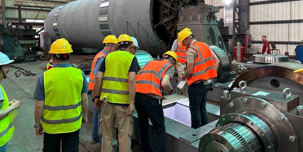
Visual inspection (VT) is the most basic and widely used nondestructive testing (NDT) method, detecting defects by directly observing the component surface. It is the simplest and most basic form of NDT and is often used as a preparatory step before more complex methods. Tools such as magnifiers, endoscopes, and industrial cameras can also be used to directly observe the surface condition of the object being inspected. Inspectors examine for visible anomalies such as cracks, dents, corrosion, deformation, and cosmetic weld defects to assess the surface quality and integrity of the material or component. It is easy to operate and low-cost, and is often used for routine equipment inspections and process inspections during the manufacturing process. Experienced non-destructive testing (NDT) experts will use their field experience and knowledge to select appropriate technologies and report the test results in a variety of report formats.
What are the adventgaes of visual testing?
- Highly flexible: Unrestricted by location or environment, it can be performed in laboratories, production lines, and outdoors. Comprehensive inspections of large equipment (such as storage tanks and bridges) can be achieved using auxiliary tools such as ladders and drones.
- Extremely broad applicability: VT can perform preliminary screening on materials ranging from metals and non-metals (plastics and ceramics) to composite materials, as well as complex shapes such as flat plates, curved surfaces, and pipes.
- Fast response: During emergency inspections (such as sudden equipment failures), testing can be initiated immediately without the need for complex equipment preparation, saving time for troubleshooting.
- Low barrier to entry and widespread adoption: The skill requirements are relatively basic (mastery is achieved through short training sessions), making it suitable for widespread adoption within the enterprise and particularly suitable for grassroots inspectors conducting routine inspections.
- Environmentally friendly: No consumables such as coupling agents or radioactive materials are required, resulting in no adverse effects on both inspectors and the environment, aligning with the concept of green testing.
What are the limitations of visual testing?
- Limited detection depth: It can only identify surface or near-surface defects, and cannot detect sub-surface defects such as internal cracks and slag inclusions like ultrasonic testing (UT) and radiographic testing (RT), and has limitations in judging the internal integrity of the material.
- Reliance on visibility: Direct visual contact is required. For the inner cavity, deep holes, and obstructed parts of complex structures, it is far less flexible than methods such as endoscopes (ET) and eddy current testing (ET). It often requires disassembly of components for detection, which increases the difficulty of operation.
- High environmental sensitivity: It has strict requirements on lighting conditions. Insufficient light or reflections will cover defects; and extreme environments (such as high temperature, radiation, and underwater) require special protective equipment. It has worse adaptability than magnetic particle testing (MT) and penetrant testing (PT).
- Strong subjectivity: The results depend on the experience and sense of responsibility of the test personnel. The same sample may draw different conclusions due to differences in personnel skills, and the accuracy is far less than that of UT, RT and other quantifiable data detection methods.
- The preliminary preparation is cumbersome: the surface must be thoroughly cleaned of oil, rust, coating and other interferences, otherwise it is easy to miss the detection. Penetrant testing (PT) has a higher tolerance for surface cleanliness, and ultrasonic testing (UT) does not require excessive pretreatment.
What is the process of performing a visual testing for a rotary kiln riding ring?
Preparation before testing
- Clear inspection standards: Based on the casting design drawings and industry specifications (such as those related to kiln equipment), determine the defect types (such as surface cracks, cold shuts, and shrinkage cavities), dimensional tolerances, and acceptance thresholds to focus on.
- Equipment and Tools: Equip a high-intensity flashlight, a magnifying glass (10-20x magnification), an endoscope (for use within casting cavities or grooves), a ruler/caliper (for measuring dimensions), recording tools (camera, record sheet), and, if necessary, a scaffold or lifting platform (for large rotary kiln castings).
- Casting Pretreatment: Remove surface dust, oil, and scale. High-pressure water jets and wire brushing can be used to expose the original surface and ensure that no defects are obscured.
Overall appearance inspection
- Macroscopic observation: Starting from the casting as a whole (such as kiln drum, wheel belt, support wheel, etc.), check whether there is obvious deformation, large-area corrosion, local bulge/depression, etc., and record the location and range of abnormal areas.
- Dimension review: Use calipers to measure key parts (such as diameter, wall thickness, assembly interface size), compare with drawings, and verify whether they meet the installation or operation requirements.
Detailed inspection of key areas
- Stress concentration areas: Focus on vulnerable areas such as welds (such as splicing), corners, and opening edges of castings, and use a magnifying glass or endoscope to check whether there are microcracks, undercuts, incomplete penetration and other defects.
- Wear and erosion area: For the inner surface in contact with the material during long-term operation of the rotary kiln, and the contact points between the support wheel and the wheel belt, observe whether there is uniform wear, local peeling or groove-shaped damage.
- Connection and sealing surface: Check the sealing of flanges and bolted connection parts, whether there are signs of leakage (such as dust accumulation, scaling) or loose or broken connectors.
Recording and determination
- Take photos of the defects found, mark the coordinates, and record the size (such as crack length, corrosion area), shape (such as linear, dot) and other information.
- Compare with the standard to determine whether the defects exceed the standard: minor defects (such as small scratches) can be marked and tracked for observation, and serious defects (such as through cracks, excessive deformation) need to be promptly fed back and further testing (such as ultrasonic testing to confirm the depth) is initiated.
Post-test processing
- Clean up the test site and perform protective treatment on the casting surface when necessary (such as reapplying anti-rust paint).
- Organize the test report, summarize the defect data and make repair or replacement suggestions to provide a basis for the maintenance plan of the rotary kiln.
What are the primary focus of visual testing?
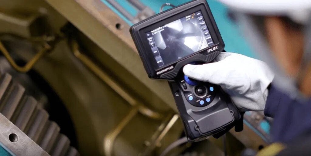
- Identify surface defects such as cracks, pores, corrosion, dents, peeling, etc., and directly determine the surface integrity of materials or components;
- Verify dimensional compliance, and ensure that the size and shape of parts meet the design standards through measuring tools (such as calipers, plug gauges) or visual comparison;
- Evaluate weld quality, check whether there are defects such as incomplete welding, weld bead, undercut, etc. on the appearance of the weld, and confirm whether the weld size (such as excess height, width) meets the standard;
- Assist other inspections, lock key areas through preliminary screening, provide direction for in-depth inspections such as ultrasonic (UT) and radiography (RT), and improve overall inspection efficiency;
- Verify assembly compliance, observe whether parts are installed in place and whether the connection is firm, and avoid problems such as wrong installation and missing installation;
- Evaluate surface finish, and determine whether processing textures, scratches, etc. meet process requirements, which is especially important for precision parts;
- Ensure operation safety, check obvious structural hazards (such as loose connectors) before inspection, and create a safe environment for other inspection methods.
- Record the initial state to provide benchmark data for the full life cycle management of the equipment, so as to facilitate the comparison of wear or deterioration in the later stage;
What are the tools used during the visual testing?
- Hardness tester: In the visual inspection (VT) of rotary kilns, although hardness testers are not traditional VT tools, they are often used as auxiliary means to verify the performance of castings. For key load-bearing castings such as the wheel belt and support roller of the rotary kiln, it is necessary to use a hardness tester (such as Rockwell hardness tester, Brinell hardness tester) to test whether the surface hardness meets the design standards - for example, if the surface hardness of the wheel belt is abnormally low, it may indicate that the material heat treatment is unqualified, and long-term operation is prone to excessive wear or deformation. Such performance defects are often associated with appearance defects such as surface cracks, which can assist VT in determining the cause of the defect. When testing, avoid obvious surface defect areas and choose flat parts for testing to ensure data representativeness.
- Mirrors: Mirrors are essential for inspecting hard-to-reach areas such as pipes, holes, castings, and corners. They are often used with a flashlight to reflect light into these areas.
- Magnifying Glasses: Available in a variety of configurations and optical intensities, these simple magnifying glasses help focus on areas of interest by magnifying identified discontinuities.
- Digital Calipers/Micrometers: Measure machined dimensions of castings (e.g., roller diameter, journal tolerances), wall thickness deviation, and verify conformance to drawings.
- Digital Indicators/Micrometers (with mounting brackets): Check casting flatness (e.g., flange surfaces) and cylindricity (e.g., roller outer diameters).
- Feeler Gauges: Check assembly clearances (e.g., clearance between tyres and retainers, misalignment in butt welds on cylinders).
- Laser Calipers: Quickly measure outer diameter deviation and ovality on large cylinders to assess machining accuracy.
- Optical Scopes and Probes: Essential for inspecting internal surfaces such as pipes and bends. They provide a close-up, magnified view, have a light source at the tip, and are often equipped with a camera for taking detailed photos and on-screen measurement software.
- Charge coupled device: Small TV cameras in the form of charge coupled devices or charge transfer devices can replace common fiber optic imaging systems.
- Finish tester (surface roughness tester): The finish of the rotary kiln's barrel butt weld, the contact surface between the support roller and the wheel belt, etc. directly affects the stability of equipment operation (for example, too rough a surface may aggravate wear or cause stress concentration). The surface finish tester can accurately measure the roughness parameters (such as Ra, Rz) of these key surfaces and quantitatively evaluate the surface processing quality or wear degree. For example, if the surface roughness of the support wheel suddenly increases, combined with the scratches and pits observed by VT, it can more accurately determine the wear rate and whether there is abnormal friction. This tool is particularly suitable for the inspection of the finished surface of castings, supplementing VT's subjective judgment of "surface smoothness" and providing a quantitative basis for equipment maintenance.
Working principle: Light Interaction with Materials in VT
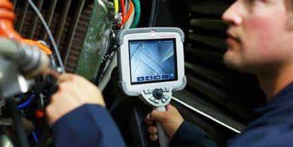
The accuracy of visual inspection (VT) is highly dependent on the visual observation and judgment ability of the inspector, and the use of light and the control of the observation angle are the key to identifying potential defects. During inspection, it is necessary to combine the characteristics of the inspected surface and understand the influence of light reflection law and observation method on defect identification:
Specular Reflection
When light hits a smooth surface (such as the finely machined rotary kiln roller journal and the chrome-plated surface of the vertical mill roller in cement equipment), it will reflect at a fixed angle (the incident angle is equal to the reflection angle). Such surfaces are prone to strong reflections, which may cover up minor defects (such as shallow scratches). During inspection, it is necessary to adjust the light source angle or use a polarized light filter to weaken the reflection to ensure that the defects are clearly visible.
Diffuse Reflection
Rough surfaces (such as the unfinished casting blank surface in cement equipment and the rusted surface of the rotary kiln cylinder) will scatter light in multiple directions. Surface defects (such as casting cold shuts and corrosion pits) are easier to identify due to the difference in reflection. During inspection, the diffuse reflection characteristics can be used to highlight the contrast between defects and the substrate through strong light irradiation at multiple angles.
Observation angle and distance
The standard requires that the distance between the inspector and the inspected surface should not exceed 600mm (24 inches), and the observation angle (the angle between the line of sight and the surface normal) should not be less than 30°. For example, when inspecting the flange surface of a cement ball mill's end cap, maintaining an appropriate distance and angle is crucial to avoid misidentifying dents or cracks due to a flat viewing angle. Observing from different angles can correct for visual deviations in defects. For example, observing the weld undercut on a vertical mill housing from the front can underestimate its depth, but shifting the angle to the side allows for a more accurate assessment of the defect size.
Peripheral Vision
When scanning the surfaces of large cement equipment (such as the entire exterior surface of a rotary kiln or the extrusion roller surface of a roller press), peripheral vision can quickly detect defects with high contrast against the background (such as obvious cracks or large areas of corrosion). This allows for the detection of anomalies even when not directly focused, improving the efficiency of large-area inspections.
2 common Visual Testing Techniques in NDT
Visual testing (VT) uses a variety of technical means to identify and evaluate discontinuous defects on the surface of materials. The classification of methods is based on the way the inspector observes the inspected surface. The specific selection needs to be combined with the accessibility and visibility of the inspection area. The core difference between direct visual testing and indirect visual testing lies in the directness of the observation path:
Direct Visual Testing (DVT)
The inspector directly observes the inspected surface with the naked eye or simple auxiliary tools. The observation angle can be adjusted with the help of a reflector, or a magnifying glass (usually 10-20 times) can be used to enhance the visibility of subtle defects. This method is suitable for scenes where the surface is easily accessible and unobstructed. It is easy to operate and has extremely low cost.
Application example of cement equipment: In the process of rotary kiln barrel segmentation, the inspector directly observes whether there are machining scratches and depressions on the flange sealing surface, or checks the casting sand holes and micro cracks on the surface of the wheel belt casting through a magnifying glass; for the butt weld of the vertical mill shell, directly check whether there are defects such as undercut and incomplete welding on the weld appearance.
Remote Visual Testing (RVT)
Use optical instruments such as endoscopes (rigid or flexible) and video endoscopes to observe inaccessible areas. Due to the reliance on professional equipment, the cost is higher than direct visual inspection, but it can break through space limitations.
Application example of cement equipment: For the inner wall of the deep hole bolt hole of the ball mill end cover, use a rigid endoscope to check whether there are casting shrinkage holes or machining burrs; for the inner cavity of the oil channel of the rotary kiln support wheel shaft, use a flexible video endoscope to observe the inner wall corrosion or foreign matter accumulation. Such areas cannot be directly observed due to the closed structure, and need to rely on remote equipment for comprehensive inspection.
Example: VT's application in Vertical roller mill steel casting part fabrication:
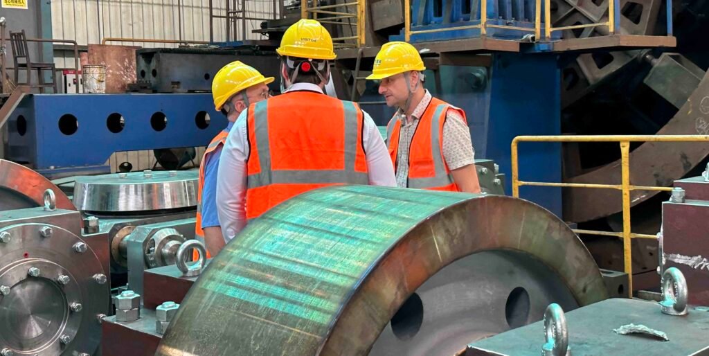
Taking the manufacturing process inspection of vertical cement mill rocker arm castings as an example:
Casting stage:
The inspector uses a 10x magnifying glass to check whether there are casting defects on the rocker arm surface through direct visual inspection (DVT) - such as shrinkage holes near the gate, cold shut cracks at the corners, and surface sand holes caused by residual molding sand; at the same time, observe whether the casting as a whole is deformed (such as bending, twisting) to ensure that the appearance meets the drawing benchmark.
Processing stage:
For the machining surface of the shaft hole connecting the rocker arm and the grinding roller, use a right-angle reflector to assist in observing whether there are burrs and scratches on the edge of the hole, and use a ruler to verify the flatness of the end face of the shaft hole; for the bolt mounting hole at the bottom of the rocker arm, use a strong flashlight to illuminate the inner wall of the hole to check whether there are machining defects such as broken teeth and missing teeth after tapping.
Verification before assembly:
When the rocker arm and the housing are pre-assembled, remote visual inspection (RVT) is used to insert a flexible endoscope into the connection gap between the two to observe whether there are foreign objects (such as iron filings) on the fitting surface or the integrity of the sealing groove to avoid oil leakage or abnormal vibration in the later operation due to defects in the assembly surface.
So above we have introduced the most common 6 type of NDT method, now if you want more NDT method we also listed some here for your reference.
Eddy Current Testing
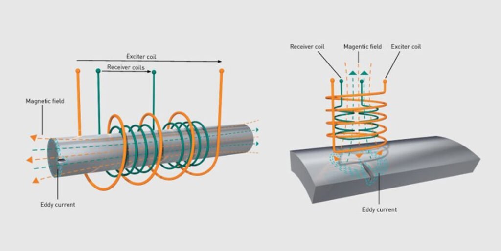
Eddy current testing (ECT) is a non-destructive testing (NDT) technique based on electromagnetic induction, specifically designed to detect surface and near-surface discontinuities (such as cracks, pits, and inclusions) in electrically conductive materials. Its working principle involves passing an alternating current through a probe coil, which generates an alternating magnetic field. When the probe is brought close to a conductive specimen, this magnetic field induces eddy currents within the material. Defects in the material disrupt the flow of these eddy currents, causing measurable changes in the probe coil’s impedance (resistance and reactance), which are analyzed by ECT instruments to identify flaw characteristics. We have covered this topic previously as well when we introduce electromagnetic flaw detection, but anyways let's get into more detail:
Core Advantages of eddy current testing in Practical Applications
- Minimal Surface Preparation: Unlike visual testing (VT) or ultrasonic testing (UT), ECT does not require removal of non-conductive surface coatings (e.g., paint, enamel) or heavy cleaning, as eddy currents can penetrate such layers. This makes it ideal for inspecting painted components like structural bolts in cement plant machinery or coated steel pipes.
- High Sensitivity and Portability: ECT equipment (including handheld probes and portable analyzers) is compact and robust, enabling on-site inspections of large or fixed assets. It can detect micro-cracks as small as a few micrometers in depth, critical for assessing fatigue damage in high-stress components.
- Real-Time Results: Instantaneous data processing allows for immediate flaw identification, supporting rapid decision-making in manufacturing or maintenance workflows—particularly valuable for time-sensitive production lines.
Key Applications Across Industries
- Surface and Near-Surface Flaw Detection: Widely used in aerospace (inspecting turbine blades for heat-induced cracks), rail (checking railhead surface defects), automotive (testing engine crankshafts for forging cracks), and manufacturing (evaluating welded joints in steel structures). In cement equipment production, ECT is applied to detect grinding cracks on the surface of rotary kiln rollers or near-surface inclusions in ball mill steel castings.
- Extended Capabilities: Beyond flaw detection, ECT can measure coating thickness (e.g., non-conductive paint on cement mixer drums), sort materials by conductivity (a proxy for alloy grade), and assess material hardness (via conductivity correlation with heat treatment status).
Specialized Application: Tube/shell Inspection
In industries like power generation and cement manufacturing, ECT is indispensable for inspecting heat exchanger tubes, condenser tubes, and boiler tubes. Using specialized probes (e.g., bobbin probes or array probes), it detects inner/outer wall corrosion, pitting, and wall-thickness reduction without disassembling the equipment. For thick-walled tubes, advanced techniques like remote field eddy current testing (RFECT) are employed to overcome signal attenuation. ECT’s non-hazardous nature (no radiation), adaptability to complex geometries, and compatibility with coated surfaces make it a versatile tool in ensuring the integrity of conductive components—from precision aerospace parts to heavy-duty cement machinery. Qualified inspectors (certified to PCN, ASNT, or EN479 standards) leverage its capabilities to deliver reliable results with minimal disruption to production processes.
Internal Rotary Inspection System (IRIS)
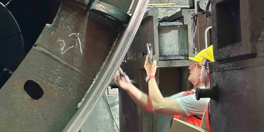
The Internal Rotary Inspection System (IRIS) is an advanced ultrasonic non-destructive testing (NDT) method specifically designed for evaluating the integrity of rotary kiln shell and tubes. Leveraging ultrasonic pulse-echo principles, it is widely recognized for its precision in detecting wall thinning, corrosion, and surface defects, making it a critical tool in industries where tube reliability directly impacts operational safety and efficiency—including cement, oil, gas, power generation, and chemical processing.
The working principle of IRIS
IRIS operates through a specialized probe inserted into the tube, which is flooded with water (serving as a coupling medium to transmit ultrasonic waves). The probe integrates a transducer that emits ultrasonic pulses parallel to the tube axis, and a rotating mirror that redirects these pulses perpendicularly into the tube wall. As the mirror rotates (driven by a turbine powered by water flow), the ultrasonic beam scans the inner and outer walls helically.
- Thickness Measurement: By calculating the time difference between echoes reflected from the inner diameter (ID) and outer diameter (OD) of the tube, IRIS precisely measures wall thickness—with accuracy often within ±0.01 mm.
- Defect Detection: Anomalies such as internal corrosion pits, external erosion, or localized wall loss disrupt the echo pattern, allowing the system to identify defect location, size, and severity.
Key Applications of IRIS
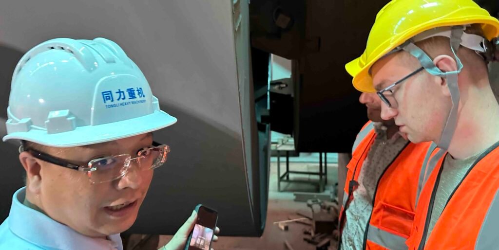
IRIS is particularly valuable for inspecting rotary kiln shell, incineration kiln shell, rotary dryer shell, heat exchanger tubes, boiler tubes, condenser tubes, and process pipes—components prone to degradation from fluid flow, temperature cycling, or chemical corrosion. In power plants, for example, it assesses steam generator tubes for thinning caused by flow-accelerated corrosion; in oil refineries, it detects pitting in hydrocarbon transport pipes. Its ability to inspect both ferrous (e.g., carbon steel) and non-ferrous (e.g., copper-nickel, titanium) tubes expands its utility across diverse material systems.
Core Advantages of IRIS
- 100% Coverage: The helical scan path ensures every point on the tube wall is inspected, eliminating blind spots—a critical improvement over partial-coverage methods like eddy current testing (ECT) for certain applications.
- Dual-Sided Sensitivity: Unlike some ultrasonic techniques, IRIS detects both internal (ID) and external (OD) defects, including subtle flaws like pinholes or circumferential cracks.
- Quantitative Data: Provides precise wall thickness measurements and defect sizing, supporting data-driven decisions on repair, replacement, or remaining service life.
- Complementary Role: Serves as a reliable backup to other tube inspection methods (e.g., remote field eddy current testing, magnetic flux leakage) when higher accuracy is required, especially for thick-walled or non-magnetic tubes.
Magnetic Flux Leakage (MFL) for Cement Equipment Inspection
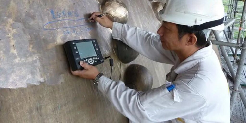
Magnetic Flux Leakage (MFL) is a reliable non-destructive testing (NDT) method used to detect corrosion, pitting, and wall loss in ferromagnetic steel components. While MFL is widely known for inspecting tank floors in the petrochemical industry, it also plays a critical role in the cement industry, particularly in inspecting large, load-bearing steel equipment that operates under extreme mechanical and thermal stresses.
Why MFL is Relevant to Cement Plant Equipment
Cement production machinery—such as rotary kilns, ball mills, vertical roller mills (VRMs), silos, and support structures—is exposed to high temperatures, vibration, and continuous mechanical loads. Over time, this environment can lead to hidden damage like:
- Wall thinning due to thermal cycling and erosion.
- Subsurface cracking in welded structures.
- Corrosion in areas exposed to moisture or chemical buildup.
These types of flaws are often not visible to the naked eye and cannot be fully evaluated with surface-only inspection methods like PT or MT. MFL, however, can detect both surface and near-subsurface discontinuities in ferromagnetic components without dismantling or extensive surface prep.
How MFL Works: its working principle
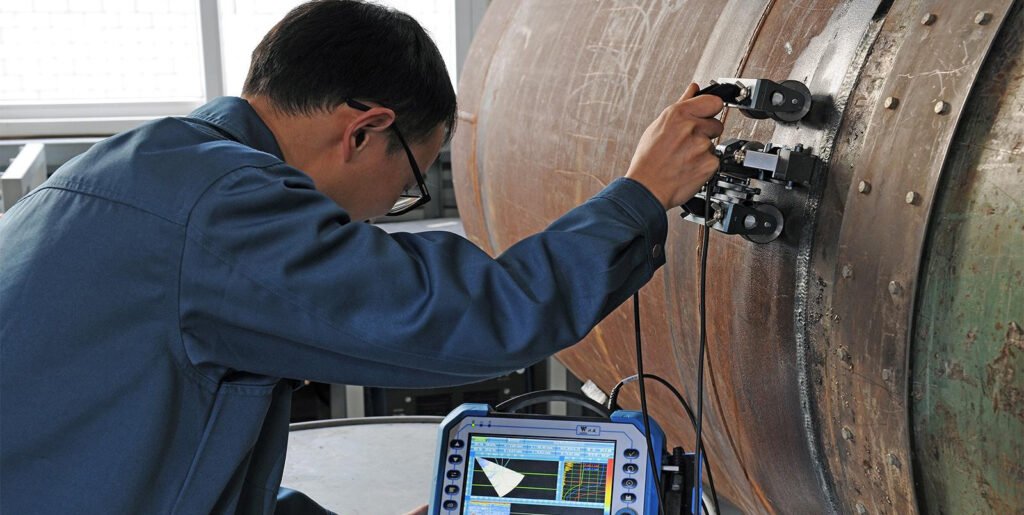
The MFL technique involves magnetizing the steel structure using a permanent or electromagnet. When the material is intact, the magnetic field flows through it uniformly. If there is metal loss, corrosion, or a defect, the magnetic field "leaks" out of the material at the damaged location. Sensitive sensors detect and quantify these leakage fields, producing a digital indication map that shows the location and relative severity of each flaw. This process is fast, non-invasive, and offers repeatable accuracy, even across large surface areas.
MFL Applications in Cement Manufacturing
MFL can be applied to several critical components across cement plants:
- Rotary Kilns: Inspection of kiln shells, especially in high-temperature zones or under tyre seats, where metal fatigue or wall thinning can cause structural compromise.
- Ball Mills & VRMs: Detection of flaws in shell plates, end welds, and pressure frame assemblies, where stress concentration may lead to failure.
- Clinker Silos & Bins: Evaluation of corrosion or wall loss in vertical silos storing abrasive and hot materials.
- Girth Gears and Support Rollers: MFL can detect cracks or corrosion at weld interfaces, gear teeth roots, and shaft couplings.
Micro and Macro Examinations
Micro and macro examinations are important non-destructive testing methods used to study the structure, quality, and properties of metal materials. These tests are helpful in cement equipment manufacturing, such as when producing or inspecting parts for rotary kilns, ball mills, vertical roller mills (VRMs), clinker coolers, and welded steel structures. They help detect issues before parts are used in harsh cement plant conditions. These examinations are done on small samples of material, taken from components or welded areas, and prepared carefully for inspection under low or high magnification.
Micro Examination – High Magnification Metal Testing
Micro examination looks closely at the inside structure (microstructure) of the material. It helps manufacturers and inspectors find issues that could affect equipment strength, safety, and lifespan. This method is useful for:
- Checking if heat treatment was done properly, which is important for parts like kiln shells or grinding rollers.
- Finding unwanted phases, inclusions, or segregation in castings used in ball mills or support bases.
- Identifying cracks, voids, or shrinkage in cast or forged parts such as trunnions or rocker arms.
- Detecting grain growth, which may weaken thick welded areas in VRM housings or kiln shells.
- Understanding how a material failed, for example, due to corrosion or fatigue cracking in high-temperature zones of a rotary kiln.
How it works:
- A small piece is cut from the part, mounted in resin, polished to a smooth finish, and treated with a chemical etchant.
- The sample is viewed under a metallurgical microscope at magnifications from 50x to over 1,000x.
- Intertek uses high-resolution cameras and microscopes to provide detailed images and analysis.
- For more advanced needs, Scanning Electron Microscopy (SEM) is also available.
Macro Examination – Low Magnification Weld Testing
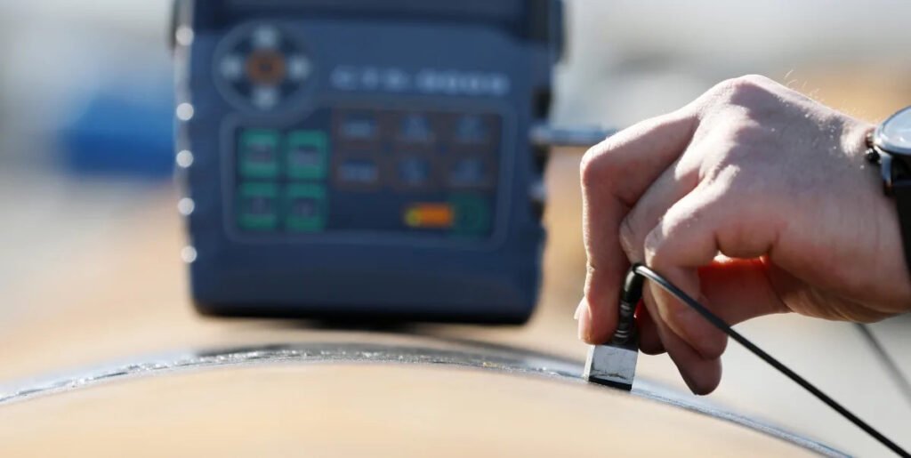
Macro examination is mainly used to check the quality of welds. It is commonly used in the cement industry for inspecting welds in kiln shells, VRM frames, ball mill sections, girth gears, and other heavy steel parts. This method is useful for:
- Checking for porosity, cracks, lack of penetration, and incomplete fusion in welded joints.
- Inspecting weld profiles to ensure compliance with welding standards used in heavy industry.
- Confirming quality according to standards such as BS EN ISO 5817, ASME IX, and AWS D1.1
How it works:
- A cross-section of the weld is taken, polished, and etched.
- The part is inspected under low magnification, usually less than 20x.
- Results help ensure that large cement equipment structures are built strong and defect-free.
What are types of not very often used non-destructive testing?
- Acoustic Emission (AE): Acoustic Emission testing listens for sound waves that come from a material when it is under stress. These sounds can mean that small cracks are forming or growing. It is used to check the health of structures like bridges, tanks, or pressure vessels while they are in use, without stopping operations.
- Infrared Testing (IR): Infrared testing uses special thermal cameras to see heat patterns on the surface of objects. If something is too hot or too cold compared to normal, it could mean there’s a problem. This method is useful for finding electrical faults, checking insulation in buildings, or spotting overheating parts in machines.
- Ground Penetrating Radar (GPR): GPR sends radar signals into the ground or other materials and measures how they bounce back. It helps to see what is below the surface without digging. GPR is used for locating pipes, cables, cracks, or hidden objects in concrete, soil, or roads. It's common in construction and archaeology.
- Guided Wave Testing (GW): This method sends low-frequency sound waves along long structures like pipelines. These waves can travel a long distance and help find problems like corrosion or cracks without needing to inspect every part directly. It saves time and is good for hard-to-reach places.
- Laser Methods (LM): Laser testing uses focused light beams to make very accurate measurements. It helps check surfaces for defects or shape changes. Some methods include laser shearography for finding hidden cracks, laser profilometry for measuring surface texture, and laser ultrasound for deeper inspections.
- Leak Testing (LT): Leak testing is used to find holes or cracks in systems that hold gas or liquid under pressure. Common methods include watching for bubbles in soapy water, using special gases to detect leaks, or measuring pressure drops. It’s important in industries like plumbing, automotive, and aerospace.
- Magnetic Flux Leakage (MFL): MFL testing checks for damage in steel, like corrosion or pits, by magnetizing the metal. If there’s a flaw, the magnetic field leaks out, and sensors can detect it. This is often used to inspect pipelines, storage tanks, and rail tracks quickly and effectively.
- Microwave Testing (MW): This method uses microwave energy to find changes inside materials. It can show problems like moisture, voids, or damage in plastics, rubber, or composite parts. Microwave testing is especially helpful for materials that don’t work well with other methods.
- Neutron Radiography (NR): Neutron radiography is like X-ray testing but uses neutrons instead of light or X-rays. Neutrons can pass through metals but show up soft materials like rubber or fuel inside. It is used in aircraft, nuclear, and defense industries to inspect sealed parts or fuel cells.
- Vibration Analysis (VA): Vibration analysis checks how machines shake or move while running. Unusual vibrations can mean problems like unbalanced parts, loose components, or worn bearings. It helps find issues early and is widely used for maintaining motors, pumps, and rotating equipment.
Below is a more detailed brief introduction, but not all of them
Phased Array Ultrasonic Testing (PAUT)
Phased Array is an advanced ultrasonic testing method that uses multiple elements in a probe to steer and focus sound waves electronically. This enables precise inspection of complex geometries, such as weld seams on curved components. In the cement industry, PAUT is ideal for detecting internal cracks and corrosion in pressure vessels, ball mill shells, and rotary kiln welds. It provides a high-resolution alternative to traditional UT, making it suitable for critical equipment with demanding performance requirements.
Time of Flight Diffraction (ToFD)
ToFD is an ultrasonic method that measures the time it takes for diffracted sound waves to travel from a flaw to receivers. It’s particularly effective for sizing and characterizing weld defects like lack of fusion or porosity. ToFD is often used in tandem with PAUT in rotary kiln and vertical roller mill fabrication, offering full volumetric coverage and high accuracy in flaw depth assessment, which is critical for assessing structural integrity in thick-walled components.
Magnetic Flux Leakage Testing (MFL)
MFL is used to detect corrosion, pitting, and material loss in ferromagnetic components by identifying disruptions in magnetic fields. In the cement industry, MFL is especially valuable for inspecting conveyor belts, ball mill liners, and rotary kiln tires where traditional UT may not be feasible. The technique is fast, covers large areas, and is often automated, improving efficiency during shutdown inspections.
Guided Wave Testing (GW)
Guided Wave Testing uses low-frequency ultrasonic waves that travel along the length of a structure, such as pipes or shafts, detecting wall loss or defects over long distances. While more common in the oil and gas industry, its potential use in long cement plant pipelines and ducts makes it valuable, especially in difficult-to-access locations like over-head ducting or preheater risers.
Ground Penetrating Radar (GPR)
GPR uses radar pulses to image subsurface structures. In the cement industry, GPR is most applicable during civil construction—such as foundations for grinding stations, silos, or storage domes. It can detect voids, rebar, or degraded concrete, ensuring structural reliability before heavy mechanical installation.
Acoustic Emission Testing (AE)
AE detects stress waves emitted from micro-crack growth or material deformation in real time. It's particularly useful for monitoring rotary kiln shells, mill bearings, and gearboxes under load. AE can be used continuously during operation, offering a predictive maintenance tool that alerts operators before catastrophic failures occur.
Thermal/Infrared Testing (IR)
IR thermography detects heat patterns on equipment surfaces, identifying hotspots, thermal anomalies, or insulation failures. In cement plants, IR is widely used to monitor rotary kiln refractory lining, electrical panels, and bearings. It allows technicians to spot overheating before it leads to equipment failure, improving safety and energy efficiency.
Microwave Testing
Microwave testing is a niche method that uses microwave energy to detect changes in dielectric properties. It can be applied to composite materials or cement-based products, particularly in R&D or in detecting moisture ingress in refractory bricks or thermal insulation systems.
Laser Testing (Shearography or Holography)
Laser-based NDT techniques like shearography detect surface strain caused by subsurface defects under stress. Though less common in cement, it can be used for critical component fatigue studies—such as evaluating the integrity of welded joints in heavy equipment frames or large-diameter kiln tires.
Leak Testing (LT)
Leak testing detects the presence and location of leaks in pressurized systems. In the cement industry, it applies to compressed air lines, cooling systems, and pneumatic conveying lines. Techniques include pressure decay, soap bubble, and helium leak testing. Preventing leaks improves plant efficiency and energy use.
Drone Testing (UAV-based Inspection)
Unmanned Aerial Vehicles (UAVs) equipped with cameras or thermal sensors are increasingly used to inspect tall or difficult-to-reach equipment such as preheater towers, stack linings, silo roofs, and rotary kilns. Drones drastically reduce the need for scaffolding or rope access, enabling safer and faster inspections, particularly during shutdowns or routine maintenance.
Types of materials you can test with NDT
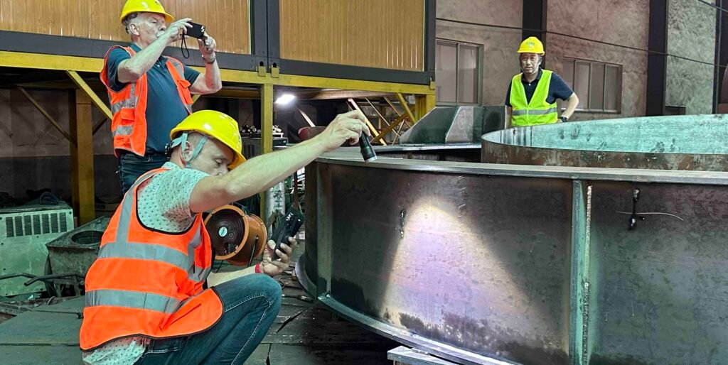
Non-destructive testing (NDT) is a valuable quality control and inspection tool that can be applied to a broad spectrum of materials across various industries. Becasue there are too many so we only list some of the materials.
Metallic materials
metallic materials, including ferrous and non-ferrous metals such as carbon steel, stainless steel, cast iron, aluminum, copper, titanium, and their alloys. These are widely used in construction, manufacturing, pressure vessels, pipelines, aerospace, automotive, cement equipment, and power generation. NDT techniques like ultrasonic testing (UT), radiographic testing (RT), and magnetic particle testing (MT) are frequently used to detect weld defects, fatigue cracks, corrosion, porosity, and material degradation in these metals without altering their integrity.
Composites
Composites are another class of materials increasingly tested using NDT. These include carbon fiber reinforced polymers (CFRP), glass fiber reinforced polymers (GFRP), aramid fiber composites, and hybrid laminates, which are used in aerospace, automotive, wind energy, and high-performance sports equipment. Due to their layered structure and anisotropic properties, specialized NDT techniques such as ultrasonic phased array, shearography, acoustic emission, and thermography are employed to detect delaminations, fiber misalignment, voids, and impact damage.
Polymers and plastics
Polymers and plastics, including thermoplastics like polyethylene (PE), polypropylene (PP), and PVC, as well as thermosetting resins such as epoxy and phenolic resins, are also subject to NDT, particularly in applications like storage tanks, pipeline linings, insulation systems, and molded parts. NDT can help identify internal voids, cracks, inhomogeneities, or poor bonding within these components using methods like radiography, visual inspection, and thermal imaging.
Ceramics and refractories
Ceramics and refractories used in high-temperature and abrasive environments—such as kiln linings, furnace bricks, and ceramic coatings—can also be evaluated through NDT methods. Ultrasonic pulse velocity testing, impact echo, and acoustic methods can detect internal cracking, shrinkage defects, and material degradation over time.
Concrete and cement-based materials
Concrete and cement-based materials, including reinforced concrete structures, pre-stressed members, and cementitious composites, are regularly inspected using ultrasonic testing, ground penetrating radar (GPR), rebound hammer, and acoustic emission techniques. These allow detection of voids, honeycombing, rebar placement, delamination, cracks, and overall structural integrity without damaging the structure.
Rubbers and elastomers
Rubbers and elastomers, used in vibration isolation, seals, gaskets, and expansion joints, can also be tested for internal defects, voids, and aging using ultrasonic testing and visual inspection techniques. These materials are often tested in the aerospace, automotive, and industrial machinery sectors.
wood and timber
Wood and timber, particularly in historical structures, bridges, or load-bearing frameworks, can be assessed with NDT using resistance drilling, ultrasound, and infrared thermography to detect rot, insect damage, or internal voids without cutting into the structure.
Other Nondestructive testing (NDT) is applicable materials, including metals, alloys, plastics, ceramics, composites, concrete, coatings, wood, glass, fiberglass, rubber, electronic components, as well as welds, pipes, castings and forgings, and can comprehensively evaluate the integrity and defects of different materials and products.
NDT Regulations,Codes and International Standards
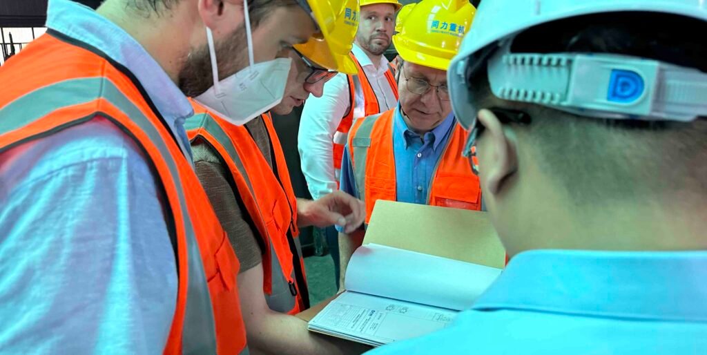
NDT techniques play a big role in the inspection and maintenance of cement plant equipment, including rotary kilns, ball mills, vertical roller mills, pressure vessels, and ducting systems. These heavy-duty assets operate under high temperatures, loads, and dynamic stresses, making them susceptible to fatigue, cracks, wear, and material degradation over time. The main regulatory standards for NDT testing include: ANSI/ASNT CP-105, Recommended Practice No. SNT-TC-1A, ISO 9712, EN 473 The above standards provide guidelines for the qualification, certification, and performance of NDT personnel, as well as the proper use of different NDT techniques and interpretation of the results.
To ensure reliability and operational safety, most cement equipment inspections must comply with recognized NDT codes and standards. Depending on the asset type and regional regulations, these may include ASME Section V (Non-Destructive Examination), ISO 9712 (Qualification and Certification of NDT personnel), EN 13445 (Unfired Pressure Vessels), or industry-specific guidelines such as those provided by FLSmidth, DIN, or national cement associations.
Inspections are often required to be performed at regular intervals during planned shutdowns or overhauls, following detailed inspection procedures tailored to each machine component. For example, rotary kiln shell welds and roller press housings may undergo ultrasonic testing (UT) and magnetic particle testing (MT) to detect internal or surface cracks, while ball mill trunnions and VRM gear housings may be inspected using radiographic testing (RT) or penetrant testing (PT) for early-stage defect detection.
In many cases, inspections must be conducted by certified NDT personnel (e.g., Level II or III per ISO 9712 or ASNT SNT-TC-1A), and results may require verification by a third-party inspection body—especially when the equipment is governed by pressure or structural safety codes. This structured approach ensures the integrity and long-term performance of key cement production assets, while meeting both legal and industry-specific compliance requirements.
NDT regulation code different region and country
| Country/Region | Regulatory Bodies | Standards & Certification Organizations | Industry Relevance |
| USA | - OSHA (Occupational Safety and Health Administration) - PHMSA (Pipeline and Hazardous Materials Safety Administration) - EPA (Environmental Protection Agency) - DOE (Department of Energy) | - ASME (American Society of Mechanical Engineers) - API (American Petroleum Institute) - ASTM International - ASNT (American Society for Nondestructive Testing) | Cement kilns, pressure vessels, piping systems, high-temperature furnaces |
| Canada | - CCOHS (Canadian Centre for Occupational Health and Safety) - NRCan (Natural Resources Canada) - CNSC (Canadian Nuclear Safety Commission) | - CSA Group - CGSB (Canadian General Standards Board) - CWB (Canadian Welding Bureau) | Cement plants, fertilizer vessels, pressure piping systems |
| United Kingdom | - HSE (Health and Safety Executive) - BEIS (Dept. for Business, Energy & Industrial Strategy) | - BINDT (British Institute of NDT) - EEMUA - BSI (British Standards Institution) | Mechanical equipment inspection, cement mills, high-pressure vessels |
| Germany | - BAuA (Federal Institute for Occupational Safety and Health) - BMWK (Federal Ministry for Economic Affairs and Climate Action) | - BAM (Federal Institute for Materials Research and Testing) - DGZfP (German Society for NDT) - DAkkS (German Accreditation Body) | Rotary kilns, ball mills, steel shells, weld inspections |
| France | - ASN (Nuclear Safety Authority) - Ministry of Labor - DGCCRF | - COFREND (French Committee for NDT) - AFNOR - COFRAC | Structural integrity testing for calcination units, chemical handling systems |
| Switzerland | - FOEN (Federal Office for the Environment) - FOCA - FOPH | - SVTI - SAS (Swiss Accreditation Service) | Mechanical integrity in fertilizer process vessels, kiln shells |
| India | - PESO (Petroleum & Explosives Safety Organization) - BIS (Bureau of Indian Standards) - DGFASLI (Directorate General, Factory Advice Service & Labour Institutes) | - ISNT (Indian Society for NDT) - IBR (Indian Boiler Regulations) - BIS | Pressure vessels in fertilizer and cement, welding inspection of heavy equipment |
| China | - AQSIQ (General Administration of Quality Supervision) - MIIT (Ministry of Industry and Information Technology) | - SAC (Standardization Administration of China) - CNAS (China National Accreditation Service) - NDT Society of China | Kilns, VRMs, heavy rotary equipment, pressure and hydraulic equipment |
| Japan | - METI (Ministry of Economy, Trade and Industry) - JIS (Japanese Industrial Standards) | - JSNDI (Japanese Society for NDT) - JIS - JSME (Japan Society of Mechanical Engineers) | Cement grinding plants, fertilizer processing units, pressure & heat exchangers |
| ISO & Global | – | - ISO 9712 (Personnel Certification) - ISO 17638 (Magnetic Testing of Welds) - ISO 5817 (Welding Quality) - ISO 13588 (Ultrasonic Testing of Welds) |
More NDT regulation code
- ISO (International Organization for Standardization): Develops global NDT standards such as ISO 9712 (Personnel Certification), ISO 17636 (Radiographic Testing), ISO 17640 (Ultrasonic Testing), and ISO 17638 (Magnetic Testing). Widely adopted across industries worldwide.
- EN (European Norms): European standards harmonized with ISO, including EN 473 and EN ISO 9712 for NDT personnel certification, and EN 1330 covering terminology and general principles.
- DIN (Deutsches Institut für Normung): Germany’s national standards body; issues DIN EN ISO 9712 and other technical standards important for mechanical engineering and heavy industry.
- BINDT (British Institute of Non-Destructive Testing): UK-based professional body responsible for certifying NDT personnel and promoting best practices aligned with ISO and European standards.
- JIS (Japanese Industrial Standards): Japan’s official standards covering NDT methods like ultrasonic, radiographic, and magnetic testing, crucial for Japanese manufacturing sectors.
- ISNT (Indian Society for Non-Destructive Testing): Indian organization that certifies NDT technicians and promotes standards consistent with ASNT and ISO, widely used in Indian heavy industries.
- COFREND (French Committee for Non-Destructive Testing Studies): Governs French NDT standards and certifications, offering industry-specific guidelines especially in nuclear, chemical, and manufacturing sectors.
- ASME BPVC Section V: Part of the Boiler and Pressure Vessel Code specifying mandatory NDT requirements for weld inspections and material testing, important for cement plant pressure vessels and rotary kilns.
- AWS (American Welding Society): Provides welding and NDT standards, such as AWS D1.1, that set acceptance criteria for weld quality in structural and manufacturing applications.
- NACE International: Focuses on corrosion prevention and standards, including NDT methods for corrosion detection and monitoring—critical for cement equipment exposed to harsh environments.
- SAFed (Safety Assessment Federation, UK): UK-based organization that sets inspection and maintenance guidelines for lifting, pressure, and mechanical equipment, relevant to cement plant infrastructure.
- TWI (The Welding Institute): A global research and certification body offering guidance on welding and NDT, widely respected in heavy equipment manufacturing.
- IEC (International Electrotechnical Commission): Develops standards for electrical and electronic inspection methods, often complementing NDT techniques in automated and remote inspections.
- API (American Petroleum Institute)
- ASME (American Society for Mechanical Engineers)
- ASTM (American Society for Testing and Materials)
- ASNT (American Society For Nondestructive Testing)
- COFREND (French Committee for Non-destructive Testing Studies)
- CSA Group (Canadian Standards Association)
- CGSB (Canadian General Standards Board)
What is the Importance of Non-Destructive Testing in Cement equipment manufacturing industry?
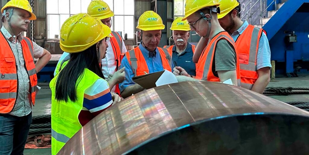
In cement plants, equipment operates under extreme conditions: high temperatures, high mechanical loads, constant vibration, and exposure to abrasive materials. Any undetected defect in critical components—such as welds on a rotary kiln shell, gear teeth on a ball mill, or cast housings of a VRM—can result in unexpected failure, extended downtime, and serious safety risks. To prevent such outcomes, manufacturers and plant operators use advanced NDT methods like ultrasonic testing (UT) to detect internal cracks or inclusions in forged parts, radiographic testing (RT) for weld seam quality, and magnetic particle testing (MT) to identify surface defects in castings and rotating parts. These techniques allow for thorough inspection without damaging or altering the equipment, which is especially important before assembly, during maintenance shutdowns, or prior to commissioning. Regular NDT inspections are not just best practice—they are often mandated by international standards such as ASME Section V, EN ISO 17638, or national welding regulations. Compliance with these standards helps ensure that cement production systems operate safely and efficiently over decades of heavy use.
Moreover, early detection of flaws—such as fatigue cracks in kiln riding rings or corrosion in pressure pipelines—can significantly reduce the risk of catastrophic failure. Avoiding unscheduled shutdowns is critical: even one day of halted clinker production due to equipment failure can result in tens of thousands of dollars in losses.
In short, NDT provides the cement equipment industry with a reliable, cost-effective means to balance quality assurance, regulatory compliance, and long-term operational performance—from manufacturing to daily plant operations.
When Is NDT Testing Required in cement industry?
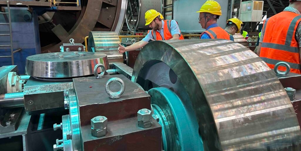
In the cement industry, the demand for nondestructive testing (NDT) is closely linked to risk control throughout the equipment lifecycle, particularly for core equipment such as ball mills, vertical mills, and rotary kilns. Specific scenarios are as follows:
During the manufacturing and acceptance phase of new equipment:
The ball mill end cap casting undergoes ultrasonic testing (UT) to detect internal metallurgical defects such as shrinkage cavities and inclusions to prevent stress concentration fractures during operation. The welded joints between the vertical mill rocker arm and the housing undergo radiographic testing (RT) to verify the presence of incomplete fusion and air holes, ensuring weld strength under heavy loads. The rolled butt welds of the rotary kiln shell undergo penetrant testing (PT) to inspect for surface cracks to prevent leakage during initial production.
During the installation and commissioning phase:
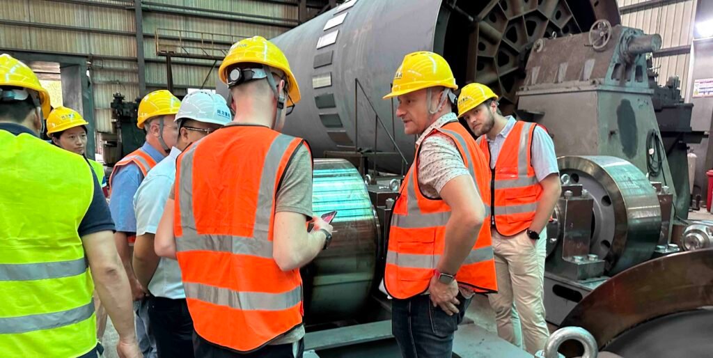
The contact surfaces between the rotary kiln roller and tyre undergo magnetic particle testing (MT) to inspect for microcracks caused by installation stress. The interference fit between the vertical mill roller shaft and the bearing seat undergoes ultrasonic thickness measurement to confirm assembly accuracy to prevent vibration caused by abnormal clearance during operation. The bolts connecting the ball mill hollow shaft and the end cap undergo ultrasonic testing to assess thread root fatigue risk and ensure overall tightness. During regular preventive maintenance, the ball mill's liner bolts undergo magnetic particle testing every 10,000 hours of operation to prevent loosening and wear of the cylinder. Ultrasonic testing is used to measure the remaining thickness of the vertical mill roller weld overlay to predict replacement intervals. Phased array ultrasonic testing (PAUT) is used every six months to detect fatigue crack growth in the contact area between the rotary kiln tyre and the backing plate to prevent kiln instability.
During equipment abnormalities and overhauls
When the ball mill experiences unusual noise, ultrasonic testing is performed to locate hidden cracks in the welds connecting the end cap and the cylinder. When vertical mill vibration exceeds the specified limit, an endoscope (ET) is used to inspect the rocker arm bearing for internal wear or roller cracks. During rotary kiln overhauls, ultrasonic testing of the roller journal is performed to assess the remaining strength after wear to prevent sudden fracture. During the life extension assessment phase for older equipment, rotary kilns over 10 years old undergo comprehensive ultrasonic thickness measurement of their cylinders to assess wall thinning trends. Ball mill frame castings undergo radiographic testing to identify internal cracks under long-term loads. This provides data support for equipment life extension and prevents safety incidents caused by material degradation.
What Is the Difference Between Destructive Testing and Non-Destructive Testing?
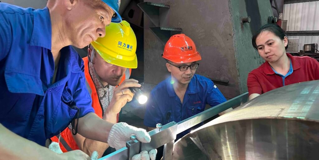
The core difference between nondestructive testing (NDT) and destructive testing (DT) lies in their impact on the material being tested. NDT, while preserving the integrity of the material, uses techniques such as ultrasound, radiography, and magnetic particle analysis to assess internal or surface defects. DT, on the other hand, destroys the material to obtain performance data, requiring the application of extreme conditions (such as high temperature and overload) until failure. NDT focuses on the material's current state and defect detection, while DT focuses on the material's ultimate performance and failure mechanisms. For example, tensile testing (DT) of cement equipment steel involves stretching the specimen until fracture to determine the tensile strength and yield point. A three-point bend test involves bending a specimen of vertical mill roller material to assess its toughness. Macrosectioning involves cutting and etching weld seam samples to observe the weld microstructure. This DT data provides a basis for material selection and design, complementing NDT.
Exmaples of destructive testing:
- Impact testing: Standard specimens made of alloy steel used in vertical mills are subjected to impact loading at low temperatures, causing them to fracture. The absorbed energy is used to assess the material's impact toughness, ensuring that the grinding rollers are resistant to sudden load breakage.
- Brinell hardness testing: A carbide ball is used to apply pressure to the surface of a rotary kiln roller, creating an indentation and measuring its diameter. Although this indentation is tiny (and destructive), it can quickly determine whether the material's hardness meets the standard.
- Corrosion testing: Coated specimens used in cement equipment are placed in a corrosive solution. After a period of time, the coating is observed for peeling and rust to assess its protective performance. This type of testing directly damages the coating's integrity.
Destructive testing vs non-destrutive testing comparison table:
| Comparison Dimension | Non-Destructive Testing (NDT) | Destructive Testing (DT) |
| Core Characteristics | Does not damage the tested material/component; integrity remains intact. Allows for repeated testing on the same item. | Requires damaging or consuming the specimen; tested material/component cannot be reused after testing. |
| Typical Application Scenarios | Used throughout equipment lifecycle stages: manufacturing, installation, operation, maintenance, and failure analysis. Ideal for detecting in-service defects and performance degradation. | Used primarily for material selection, process validation, and determining ultimate material properties. Commonly applied during new product development or incoming raw material inspection. |
| Examples in Cement Industry | 1. Ultrasonic Testing (UT) to detect incomplete fusion in rotary kiln shell welds. 2. Magnetic Particle Testing (MT) to identify surface cracks on ball mill liner bolts. 3. Endoscopic Inspection (ET) to observe wear inside vertical roller mill grinding rollers. | 1. Tensile testing on vertical roller mill arm steel to determine yield strength. 2. Impact testing of rotary kiln riding ring castings to evaluate low-temperature toughness. 3. Burst pressure testing on cement piping samples to establish pressure limits. |
| Common Methods | Ultrasonic Testing (UT), Radiographic Testing (RT), Magnetic Particle Testing (MT), Penetrant Testing (PT), Eddy Current Testing (ECT), Visual Testing (VT), Eddy Current Array (ECA), Phased Array Ultrasonic Testing (PAUT). | Tensile Test, Bend Test, Impact Test (Charpy/Izod), Hardness Testing (Brinell/Rockwell/Vickers), Metallographic Analysis, Corrosion Immersion Tests. |
| Typical Test Outcomes | Focuses on defect detection: location, size, and current material condition. Provides data for safety assessment, maintenance planning, and remaining life evaluation. | Emphasizes ultimate material properties (e.g., tensile strength, impact energy), microstructure, and fracture characteristics. Data supports design validation, process improvement, and quality control. |
What is Welding NDT?
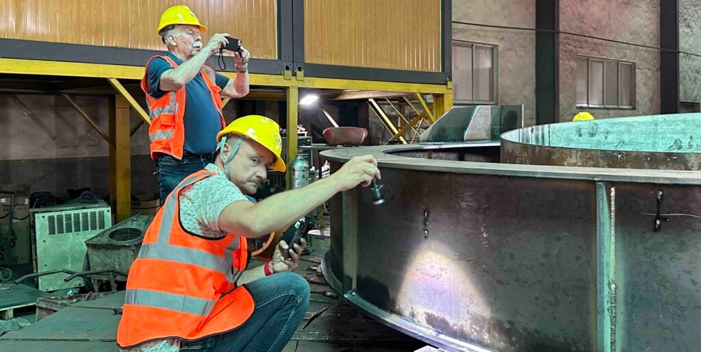
Welding NDT is performed by inspectors who are certified in accordance with ISO and SNT-TC-1A standards to evaluate the quality and integrity of welded joints without causing any damage to the weld or the base materials.
What are the Benefits of our Non-Destructive Weld Testing?
- Ensure regulatory compliance: Strictly comply with local government safety regulations and equipment inspection requirements for the cement industry (such as the Cement Plant Design Specifications) to mitigate production license risks caused by equipment noncompliance.
- Align with standards and technical specifications: Testing processes and results are fully aligned with industry standards (such as GB/T 30574 "Rotary Kiln" and JB/T 1090 "Vertical Mill for Cement Industry") to ensure the manufacturing and maintenance accuracy of core equipment such as ball mills and rotary kilns.
- Strengthen quality control throughout the entire process: Through regular nondestructive testing (such as monitoring the thickness of the vertical mill roller overlay layer and flaw detection of ball mill liner bolts), quality standards are embedded throughout the entire production chain to prevent unqualified parts from entering the next process.
- Efficient on-site process testing: Given the large-scale nature of cement equipment, rapid testing can be performed in the manufacturing workshop or installation site (such as real-time UT monitoring during rotary kiln shell welding), reducing process wait times. Closed-loop defect handling before shipment: Defects (such as undercuts on vertical mill shell welds and microcracks on rotary kiln tyres) are located and repaired on-site using VT and MT before equipment leaves the factory, avoiding the surge in post-sales rework costs.
- Systematic inspection process planning: Incorporating the structural characteristics of cement equipment (such as the complex casting structure of the ball mill end cap), a standardized process covering inspection points, tool selection, and judgment criteria is developed to ensure no blind spots in inspection.
- Digital record traceability: Inspection data (such as weld UT maps and rotary kiln wall thickness measurements) is digitally archived to support full lifecycle traceability and provide data support for equipment maintenance and overhaul.
- Reducing corporate safety liability risks: Documented inspection records and safety standards (such as tyre fatigue crack inspection reports) clarify equipment status, enable accountability in the event of anomalies, and mitigate legal disputes. Accurately identify weld root defects: For key welds in cement equipment (such as the circumferential seam of the rotary kiln shell and the weld connecting the rocker arm and the base of the vertical mill), UT or RT can be used to accurately detect hidden defects such as root corrosion and lack of fusion, thus preventing major accidents caused by weld failure during operation.
What is the best NDT welding inspection method?
When it comes to welding inspection, no single non-destructive testing (NDT) method is the all time "best". The ideal technique depends on the weld type, material, and expected defects. However, ultrasonic testing (UT) and radiographic testing (RT) are the 2 most widely used for detecting internal flaws like lack of fusion, porosity, or inclusions in critical welded joints. UT is preferred for its ability to detect precise defect locations without radiation, especially in thick or critical components such as pressure vessels and structural welds. Radiographic testing, on the other hand, is excellent for volumetric inspection and visualizing internal imperfections, though it requires strict radiation safety protocols. Surface-level inspections often begin with visual testing (VT), followed by magnetic particle testing (MT) or liquid penetrant testing (PT) to detect cracks or surface discontinuities. Advanced methods like Phased Array Ultrasonic Testing (PAUT) and Time of Flight Diffraction (ToFD) offer higher resolution and data-rich results, making them ideal for critical weld evaluation in industries such as cement equipment manufacturing, pipelines, and pressure systems.
What Company offer NDT for cement machinery?
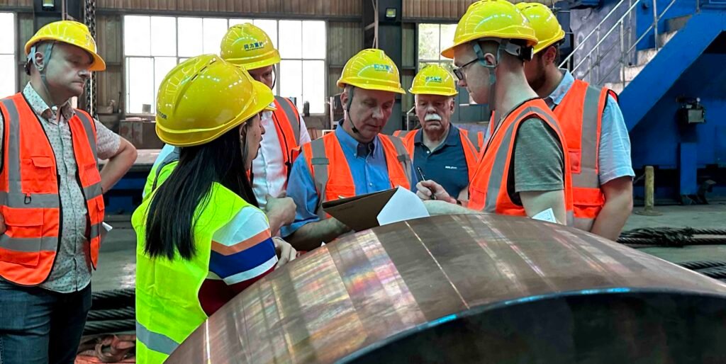
So previously we have covered ASNT and Intertek, then what are the other company that offer similar service? Below is the answer by Gemini
SGS
SGS is a Swiss multinational company, established in 1878, and stands as the world's leading inspection, verification, testing, and certification company. They offer a comprehensive range of NDT services, both traditional and advanced, to industries such as oil & gas, power generation, manufacturing, and construction. SGS's NDT solutions are integrated with their broader asset integrity management services, providing clients with data and insights throughout the entire lifecycle of their assets, from design and procurement to installation and operation, with a strong emphasis on ensuring reliability, safety, and regulatory compliance through their vast global network of laboratories and highly certified personnel.
Bureau Veritas
Bureau Veritas is a French company, founded in 1828, specializing in testing, inspection, and certification (TIC) services. They provide a wide array of NDT services to ensure the quality, safety, and performance of industrial assets, components, and structures across diverse sectors including marine and offshore, oil and gas, power, and infrastructure. Bureau Veritas leverages its global presence and extensive technical expertise to offer both conventional and advanced NDT methods, helping clients identify defects, assess material integrity, and ensure compliance with international standards and specific project requirements, ultimately contributing to risk mitigation and improved operational efficiency.
TÜV Rheinland
TÜV Rheinland is a German multinational corporation, established in 1872, and is a world-renowned independent service provider for quality and safety. They offer an extensive portfolio of Non-Destructive Testing (NDT) services, both conventional and advanced, to a wide range of industries including industrial components, energy, infrastructure, and transportation. TÜV Rheinland's NDT expertise helps clients ensure the integrity and safety of their materials, components, and structures throughout their entire lifecycle, from manufacturing and commissioning to in-service inspections and decommissioning. Through their global network of laboratories and highly qualified NDT personnel, they provide essential data for asset integrity management, helping to reduce risks, prevent failures, and ensure compliance with international standards and regulations.
Conclusion:
So in this article, we have covered almost all of the key NDT methods commonly applied in cement equipment manufacturing and maintenance, including visual inspection (VT), ultrasonic testing (UT), radiographic testing (RT), magnetic particle testing (MT), liquid penetrant testing (PT), eddy-current testing (ET), and advanced techniques like phased array (PA) and time-of-flight diffraction (ToFD). Each method offers specific advantages depending on the material, geometry, and inspection goals—whether it’s detecting surface cracks on ball mill shell welds, identifying internal flaws in rotary kiln girth gears, or assessing structural integrity of vertical roller mill components. As cement production lines operate under high loads, thermal cycles, and abrasive environments, implementing the right NDT strategy is not only essential for quality assurance during fabrication but also for predictive maintenance and extending equipment life. Choosing the appropriate combination of techniques—guided by industry codes, risk levels, and equipment criticality—helps manufacturers and plant operators minimize failures, meet compliance standards, and ensure safe, efficient operation.