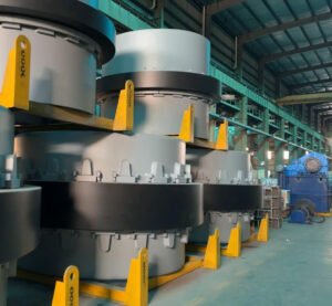
Tongli ball mill big gear(aka girth gear/large gear), as the core transmission component of the ball mill, is made of high-quality cast steel materials such as ZG42CrMo. It is carefully smelted in TONGLI foundry three-phase electric furnace, and the liquid metal is perfectly formed in the alkaline phenolic resin sand mold to create a solid and stable structure. After casting, it undergoes high-temperature normalizing at 850℃, air-cooled quenching at 600℃, and then tempered at 500-600℃. The complex heat treatment process allows the gear hardness to reach above HB170, with both high strength and excellent toughness, and can easily cope with harsh working conditions. The large gear is cleverly combined in two halves(for gear diameter over 3m), which is convenient for installation and later maintenance. After assembly, the tooth surface accuracy reaches the micron level, the meshing is precise, the transmission efficiency exceeds 98%, and the operation is smooth and smooth. Advanced CNC hobbing technology carves the tooth shape, and the tooth surface roughness Ra≤3.2μm, which reduces friction loss, reduces energy waste, and has a significant energy-saving effect. At the same time, it strictly follows the UT/MT/PT flaw detection standards, and ultrasonic flaw detection is performed to ensure that there are no defects such as cracks and pores inside, and the quality is fully guaranteed. Common module tooth numbers cover a wide range, from Φ900 - Φ6200 ball mills can be adapted, and support personalized customization to meet your diverse needs. Choose Tongli ball mill large gear to inject strong power into efficient and stable production.


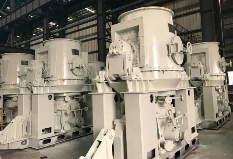
We are the manufacturer
TONGLI-Ball Mill Accessories Expert
TONGLI using advanced CNC gear hobbing technology, the tooth surface roughness is controlled at Ra≤3.2μm, which greatly reduces the friction coefficient during gear meshing, and the wear rate is reduced by more than 30% compared with ordinary processing technology, extending the service life.
The large gear of Tongli ball mill adopts advanced CNC machining equipment and implements strict machining standards. The large gear of the two-half design has excellent closing accuracy after each processing is completed. Through high-precision positioning tooling and CNC testing equipment, the radial deviation of the two semicircles at the joint is controlled within ±0.08mm, and the axial deviation does not exceed ±0.1mm. When machining the tooth surface, the grinding process is used, and the cumulative error of the tooth pitch is controlled within ±0.05mm, and the tooth shape error is within the range of ±0.03mm, which makes the gear meshing contact more closely and evenly, effectively improves the transmission efficiency, reduces the operating noise, reduces wear, and extends the overall service life of the gear and the ball mill, providing a solid guarantee for the stable operation of production.
Tongli ball mill large gears show industry-leading precision in hole processing. We use advanced five-axis linkage machining centers and professionally customized high-precision drills to perform fine operations on key holes used to connect the ball mill. Through intelligent programming and precise control of the CNC system, the positioning accuracy of the hole can reach ±0.05mm, and the hole diameter tolerance is strictly controlled at ±0.03mm. Whether it is a regular order for mass production or customized requirements, the hole positions of each batch of large gears can maintain a high degree of consistency. This means that whenever you purchase a Tongli ball mill large gear, it can be seamlessly connected with various types of ball mills that have been sold, and the installation can be easily completed to ensure a stable connection and smooth transmission, greatly reducing on-site assembly and debugging time, and effectively improving production efficiency.
The large gear of Tongli ball mill is made of high-quality alloy cast steel material, and strict control is carried out in the heat treatment link. First, high-temperature normalizing treatment is carried out, heated to 860-880℃, and kept warm for 2-3 hours to evenly refine the grains and eliminate casting stress. Then quenching, rapid cooling in oil cooling medium, so that the tooth surface obtains high hardness martensitic structure. Finally, tempering is carried out at 550-600℃ to eliminate quenching internal stress and improve toughness. After this process, the hardness of the tooth surface reaches HRC45-50, and the core maintains good toughness with a hardness of HB220-250. This ideal hardness gradient distribution greatly improves the wear resistance, fatigue resistance and load-bearing capacity of the gear. Under long-term heavy-load conditions, the wear rate is reduced by more than 40% compared with ordinary heat-treated gears, providing a reliable core transmission component for the stable operation of the ball mill.
| Ball Mill Specifications (Diameter × Length mm) | Large Gear Diameter (mm) | Large Gear Module | Large Gear Weight (kg) |
| Φ1500×3000 | 2500 | 22 | 2785.6 |
| Φ2100×4500 | 3200 | 25 | 4482.3 |
| Φ2400×5000 | 3600 | 28 | 6217.9 |
| Φ3000×6000 | 4500 | 32 | 9376.4 |
| Φ3600×6000 | 5200 | 36 | 12895.7 |
| Φ4200×7000 | 5800 | 40 | 18654.3 |
| Φ4800×7500 | 6500 | 45 | 25348.6 |
| Φ5500×8500 | 7200 | 50 | 34762.9 |
| Φ6200×9500 | 8000 | 55 | 46893.2 |
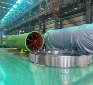
The girth gear of the ball mill is the "heart" of the ball mill transmission. It is a large-diameter ring-shaped metal casting part with gear teeth evenly distributed along the circumference. It varies according to the specifications of the ball mill and is often split for easy transportation and installation. When working, it meshes with the small gear, which is connected to the motor or the output shaft of the reducer. The motor drives the small gear, which drives the large gear to rotate the ball mill cylinder. The grinding media and materials in the cylinder are lifted and dropped by centrifugal force and friction under the rotation of the cylinder, smashing the materials to achieve powder grinding. Its material is mostly high-quality alloy steel or medium carbon steel such as 45 steel and 40Cr. After quenching, carburizing and other treatments, the tooth surface is hard and wear-resistant, and the core has good toughness, which can resist huge loads and friction and avoid breakage.
One piece ball mill large girth gear:
1. Forging: Integral large gears are usually produced by forging. First, the blank is heated to a suitable forging temperature range, generally around 1100-1200℃, and then large forging equipment, such as hydraulic presses or air hammers, is used to improve the internal structure of the metal through multiple upsetting and drawing processes, making it more dense and uniform, and improving the comprehensive mechanical properties of the gear. For example, for an integral large gear with a diameter of 2-3 meters, the forging ratio may be between 3-5.
2. Machining: The gear blank after forging needs to be machined, including tooth profile processing, inner hole processing, end face processing, etc. Tooth profile processing often uses processes such as hobbing and gear shaping, and the processing accuracy can reach level 6-7 in the GB/T 10095-2008 standard. Taking hobbing as an example, the speed of the hob depends on the module and accuracy requirements of the gear, generally between 50-200 rpm.
3. Strength and stability: The integral gear has a solid structure, high strength, and can withstand large loads. Since it is an integral part, there is no joint gap, and it has good stability at high-speed rotation, and the vibration and noise are relatively small. For example, in some large ball mills, when the mill speed is 20-30 rpm, the integral gear can ensure the smoothness of the transmission, and the vibration amplitude is generally between 0.05-0.1mm.
4. Transmission accuracy: The integral gear has high processing accuracy, small tooth shape error and tooth direction error, which can ensure good meshing with the pinion, thereby improving transmission efficiency and transmission accuracy. Under normal working conditions, its transmission efficiency can reach 98%-99%.
Split gear
1. Casting: Split gears are mostly made by casting. First, a mold is made, and then the molten metal liquid, such as cast iron or cast steel, is poured into the mold for molding. For large split gears, some special casting processes, such as lost foam casting or precision casting, may be used to ensure the quality of the casting. During the casting process, the pouring temperature and speed must be strictly controlled. For example, for large gears made of cast steel, the pouring temperature is generally 1500-1550℃.
2. Splicing and assembly: After the two half gears are machined, they need to be spliced and assembled. During the splicing process, it is necessary to ensure that the mating surfaces of the two half gears are tightly fitted, and usually dowel pins and high-strength bolts are used for connection. There are strict requirements for the tightening torque of the bolts. For example, for M30 bolts, the tightening torque may be between 1000-1200N・m to ensure that the half-type large gear can withstand a large torque during operation.
3. Convenience of transportation and installation: The biggest advantage of the half-type large gear is that it is easy to transport and install. Because it is divided into two half gears, for some large gears that are large in size and difficult to transport, it can be more convenient to transport them to the site by road, rail and other transportation methods after splitting. During installation, no large lifting equipment is required for overall lifting, which reduces the difficulty and cost of installation. For example, for large gears with a diameter of more than 4 meters, the half-gear structure can control the weight of each half gear to about 10-15 tons, which is convenient for transportation and installation.
4. Maintenance: If a part of the half-gear is damaged, such as tooth surface wear or partial fracture, the damaged half gear can be removed for repair or replacement without replacing the entire large gear, thereby reducing maintenance costs and downtime.
1. Medium carbon steel #45 steel: It is a medium carbon steel with certain strength and hardness. After appropriate heat treatment, it can obtain good comprehensive mechanical properties and meet the use requirements of general ball mill gears. It is often used in small ball mills or those with low performance requirements. Its tensile strength can reach more than 600MPa, and its hardness is generally between HB170-217.
2. Alloy structural steel 40Cr: It is a typical alloy structural steel with high strength, toughness and wear resistance. Compared with 45 steel, 40Cr steel has higher tooth surface hardness and better core toughness after quenching and surface quenching. It can withstand greater loads and impacts and is suitable for medium and large ball mills. Its tensile strength is usually above 980MPa, and its tooth surface hardness can reach HRC50-55.
2.1 Alloy structural steel 35CrMo: This alloy steel has good comprehensive mechanical properties, especially it can still maintain high strength and toughness at high temperature, and has good fatigue resistance and wear resistance. It is often used in large ball mills or places with harsh working conditions and high requirements for gear performance. Its tensile strength is generally above 900MPa, and after heat treatment, the tooth surface hardness can reach HRC40-45.
3. Cast steel ZG310-570: It is a medium carbon cast steel with good strength and toughness, good casting performance, and can be made into large gears with complex shapes. It is suitable for some ball mills with special requirements for gear size and shape. Its yield strength is 310MPa and its tensile strength is 570MPa. After proper heat treatment, its hardness and wear resistance can be improved.
3.1 Cast steelZG42CrMo: It is a high-alloy cast steel with high strength, toughness and fatigue resistance, and can withstand the huge impact and load of the ball mill during operation. It is often used in the manufacture of large gears for large and heavy-loaded ball mills. Its tensile strength can reach over 1080MPa. After tempering and surface quenching treatment, the tooth surface hardness can reach HRC50 - 55.
1. Consider the specifications and power of the ball mill
Mill diameter: Large ball mills have large diameters and heavy cylinders, so they need large modulus, large diameter and large gears to transmit power and bear large loads; small ball mills use small modulus and small size gears. For example, for a large ball mill with a diameter of 3-5 meters, the diameter of the large gear may be 2-3 meters, and the modulus is 20-30; for a small ball mill with a diameter of 1-2 meters, the diameter of the large gear is 0.5-1 meter, and the modulus is 8-12.
Mill power: A ball mill with high power needs a large gear to transmit greater torque. For a ball mill with a power of 500-1000kW, the large gear must have sufficient strength and tooth surface hardness, and the material can be selected from alloy structural steels such as 40Cr and 35CrMo; for a small ball mill with a power of less than 200kW, ordinary medium carbon steel large gears such as 45 steel can be used.
2. Consider working conditions
Material properties: When processing hard and abrasive materials, such as quartz and iron ore, the large gear needs to be made of a material with good wear resistance, such as ZG42CrMo cast steel; when processing softer materials, such as limestone and gypsum, the wear resistance requirement is lower, and ZG310-570 cast steel can be used.
Working environment: In a humid or corrosive medium environment, the large gear needs to be corrosion-resistant, and the gear surface can be treated with anti-corrosion treatment, such as hard chrome plating, spraying anti-corrosion coating, or stainless steel.
3. Consider transmission requirements
Transmission ratio: Determine the transmission ratio according to the speed of the ball mill and the speed of the motor, and select the large and small gears with the appropriate gear ratio to ensure that the ball mill reaches the required speed and achieve efficient grinding. For example, if the ball mill requires a speed of 20-30 rpm and the motor speed is 1450 rpm, the number of teeth of the large and small gears can be determined by calculating the transmission ratio.
Transmission accuracy: For ball mills with high grinding accuracy requirements, large gears with high transmission accuracy are required. Large gears with high processing accuracy are selected, such as the 6-level accuracy in the GB/T 10095-2008 standard, to ensure the uniformity of material grinding.
4. Consider materials and manufacturing processes
Material selection: Select materials according to the working conditions and performance requirements of the ball mill. For large ball mills that bear heavy loads and impacts, high-strength and high-toughness 40Cr, 35CrMo alloy structural steel or ZG42CrMo cast steel are selected; for small ball mills under general working conditions, 45 steel or ZG310-570 cast steel can meet the requirements.
Manufacturing process: Integral large gears have high strength and good stability, but are difficult to transport and install, and are suitable for small ball mills or occasions with large installation space; split large gears are easy to transport, install and maintain, and are suitable for large ball mills or occasions with limited installation and maintenance conditions.
5. Consider cost and cost performance
Initial cost: The cost of large gears with different materials and manufacturing processes is different. The cost of large gears made of alloy structural steel and cast steel and processed with high precision is high, while the cost of large gears made of ordinary medium carbon steel and processed with lower precision is low. Under the premise of meeting the working requirements of the ball mill, select the appropriate large gear according to the budget.
Operating cost: Although the initial cost of large gears with good wear resistance and long service life is high, they can reduce the number of repairs and replacements, reduce operating costs and downtime, and have a high overall cost performance. For example, although the purchase cost of large gears made of ZG42CrMo is higher than that of 45 steel, it has a long service life under harsh working conditions and the overall cost may be lower.
6. Consider brand and after-sales service
Brand reputation: Choosing a large gear manufacturer with a well-known brand like TONGLI and good reputation will ensure product quality and performance. The brand reputation of the manufacturer can be understood through market research, user evaluation, and industry recommendations.
After-sales service: Good after-sales service is very important, including installation guidance, commissioning, maintenance, and spare parts supply. TONGNLI can provide after-sales service in a timely manner, which can reduce the downtime of ball mill failures and ensure normal production.
1. Raw material preparation
Cast steel gear: usually scrap steel, pig iron, etc. are used as the main raw materials. According to the composition of the required steel, appropriate amounts of alloy elements (such as chromium, molybdenum, manganese, etc.) are added for batching. These raw materials are smelted in an electric furnace or converter, and molten steel that meets the requirements is obtained by strictly controlling the smelting temperature, time and chemical composition.
Forged gear: generally high-quality steel billets that have been rolled or forged are used as raw materials, and common ones are medium carbon steel or alloy structural steel. The quality of the billet is crucial to the performance of the forged gear, so it must be strictly inspected, including chemical composition analysis, flaw detection, etc., to ensure that there are no defects.
2. Forming process
Cast steel gear: The molten steel is poured into the pre-made casting mold. Under the action of gravity, the steel fills the casting mold cavity. After it cools and solidifies, a gear blank with the same shape as the casting mold is formed. The casting mold is usually made by sand casting or precision casting. Sand casting has a low cost and is suitable for large gears, but its dimensional accuracy and surface quality are relatively poor; precision casting can achieve higher dimensional accuracy and surface quality, and is suitable for some small cast steel gears with high precision requirements.
Forging large gears: It is to apply external force to the steel billet heated to a certain temperature to make it plastically deform, so as to obtain the required gear shape and internal structure. The forging process usually adopts free forging or die forging. Free forging is suitable for the production of small batches and large gears. The upper and lower anvils of the forging equipment are used to perform multiple upsetting and drawing operations on the billet to improve the internal structure of the steel and improve its mechanical properties, but the dimensional accuracy is low; die forging is to put the billet into a fixed mold and fill the mold cavity under the action of the press, so as to obtain a gear blank with high dimensional accuracy and good surface quality, which is suitable for mass production.
3. Heat treatment process
Cast steel large gears: Since some casting defects (such as pores, shrinkage, etc.) and coarse grain structure will be formed inside the gear during the casting process, heat treatment is usually required to improve its performance. Common heat treatment processes include normalizing, tempering, quenching and tempering. Normalizing can refine the grains and improve strength and hardness; tempering is used to eliminate the internal stress after normalizing or quenching and reduce the brittleness of the material; quenching and tempering can significantly improve the comprehensive mechanical properties of the gear to meet the requirements of use.
Forged large gear: The internal structure of the gear blank after forging has been significantly improved, but its performance still needs to be further improved through heat treatment. The common heat treatment processes for forged gears are similar to those for cast steel gears, such as tempering, surface quenching, etc. Tempering can make the heart of the gear obtain good comprehensive mechanical properties, while surface quenching can improve the hardness and wear resistance of the gear tooth surface while maintaining the toughness of the heart, thereby improving the bearing capacity and service life of the gear.
4. Machining process
Cast steel large gear: After heat treatment, the cast steel gear blank needs to be machined to achieve the design size and accuracy. The machining process includes rough machining, semi-finishing and finishing processes. First, rough machining is performed to remove most of the excess and leave a certain amount of machining allowance for subsequent finishing; then semi-finishing is performed to further improve the dimensional accuracy and surface quality of the gear; finally, finishing is performed, such as tooth profile processing (using methods such as hobbing and gear shaping), tooth surface grinding, etc., to obtain high-precision tooth profile and low-roughness tooth surface.
Forged large gears: The machining process of forged gears is similar to that of cast steel gears, but because the dimensional accuracy and surface quality of forged gears are relatively high, the machining allowance can be appropriately reduced during the machining process to improve the machining efficiency. In terms of tooth profile processing, forged gears usually use high-precision hobbing or grinding technology to ensure the transmission accuracy and load-bearing capacity of the gears.
5. Quality inspection
Cast steel large gears: Quality inspection includes appearance inspection, dimensional accuracy measurement, chemical composition analysis, mechanical properties testing, and non-destructive testing. The appearance inspection mainly checks whether there are defects such as sand holes, pores, cracks, etc. on the surface of the gear; the dimensional accuracy measurement uses measuring tools (such as calipers, micrometers, three-dimensional measuring machines, etc.) to detect the various dimensions of the gear to ensure that it meets the design requirements; the chemical composition analysis uses equipment such as spectrometers to detect the chemical composition of the gear to ensure that the composition meets the standards; mechanical property tests include tensile tests, impact tests, hardness tests, etc. to evaluate the strength, toughness and hardness of the gear; non-destructive testing uses ultrasonic flaw detection, magnetic particle flaw detection and other methods to detect whether there are defects such as cracks inside and on the surface of the gear.
Forged large gears: The quality inspection content is similar to that of cast steel gears, but due to the characteristics of the forging process, forged gears have stricter requirements in terms of mechanical properties and internal quality. In terms of non-destructive testing, forged gears usually require more stringent flaw detection to ensure that there are no tiny cracks or defects caused by the forging process inside. In addition, for some high-precision forged gears, the gear accuracy level needs to be tested. According to relevant standards (such as GB/T 10095-2008), the gear tooth profile error, tooth direction error, pitch cumulative error and other indicators should be tested to ensure the transmission accuracy and stability of the gear.
1. Tooth profile optimization: Traditional ball mill large gears mostly use involute tooth profiles. Although they are widely used, they are not the optimal solution under certain working conditions. At present, innovative designs such as modified involute tooth profiles and double arc tooth profiles are emerging. The modified involute tooth profile can effectively compensate for gear manufacturing and installation errors by slightly trimming the standard involute, reducing meshing impact and vibration, making operation smoother, and improving transmission efficiency by 3%-5%. The double arc tooth profile has a unique concave and convex tooth profile. Compared with the involute tooth profile, the contact stress is reduced by 20%-30%, the tooth surface wear is greatly reduced, and the gear service life is significantly extended, which shows its advantages in heavy-duty ball mills. In terms of tooth profile parameter optimization, a reasonable increase in the overlap is very effective. Through precise calculation and simulation analysis, the tooth width can be increased moderately and the modulus can be reduced, which can increase the overlap from the conventional 1.5-1.7 to 1.8-2.0, increase the number of teeth participating in the meshing at the same time, distribute the load evenly, reduce the force on a single tooth, and greatly improve the transmission stability and carrying capacity.
2. Structural optimization:
From the perspective of the overall structural layout, it is crucial to reasonably adjust the number and shape of spokes. Finite element analysis shows that compared with the traditional straight spoke structure, the stiffness of the large gear can be increased by 15%-20% by using curved spokes or variable cross-section spokes. Curved spokes can better disperse the load transmitted by the cylinder and avoid stress concentration; variable cross-section spokes increase the material thickness at key locations according to the force distribution to improve the structural strength. In the design of the hub, it is of great significance to optimize the connection method between the hub and the cylinder. Abandoning simple bolt connections, using interference fit and key connections, or welding integrated structures, can enhance connection reliability and reduce the risk of loosening. Interference fit and key connection, with the fit accuracy controlled at H7/js6, can withstand greater torque; the welded integrated structure eliminates the connection gap, allowing load transmission to be smoother and increasing the load-bearing capacity by more than 30%. Lightweight design of large gears reduces weight while ensuring strength, which not only reduces material costs, but also reduces startup and operation energy consumption. Using topological optimization technology, non-critical parts of materials are accurately removed, while maintaining stiffness and strength, achieving a weight reduction of 10%-15%, helping the ball mill to save energy and increase efficiency.
3. Material optimization
Select high-performance alloy steel: In some occasions where the performance requirements of ball mill large gears are high, high-performance alloy steel containing alloy elements such as chromium, nickel, and molybdenum can be selected. These alloy elements can improve the strength, toughness and wear resistance of steel. For example, 35CrMo steel has good strength and toughness, and is suitable for large gears of ball mills that bear large impact loads; 42CrMo steel has better comprehensive performance, with a tensile strength of more than 1080MPa and a yield strength of not less than 930MPa, and is often used for large gears of large and heavy-loaded ball mills.
Surface strengthening treatment: Carburizing, nitriding and other surface strengthening processes can form a hardened layer with high hardness and good wear resistance on the surface of large gears. Taking carburizing treatment as an example, the depth of the carburizing layer is generally controlled at 0.8-1.2mm, and the surface hardness can reach HRC58-62, which can significantly improve the wear resistance, anti-bonding ability and contact fatigue strength of the tooth surface. At the same time, the gears after nitriding treatment have high bite resistance and corrosion resistance, and can maintain good performance in harsh working environments.
4. Manufacturing process optimization
Precision processing and quality control: Use advanced processing equipment and processes, such as high-precision CNC gear hobbing machines, gear grinding machines, etc. to improve the processing accuracy of gears. For ball mill gears, the tooth profile accuracy is usually required to reach IT6-IT7 level, and the tooth direction accuracy is required to reach IT7-IT8 level. At the same time, strengthen the quality inspection link, use three-coordinate measuring instruments and other precision measuring equipment to strictly inspect the various parameters of the gear to ensure the processing accuracy and quality stability of the gear.
Optimize the heat treatment process: In addition to conventional heat treatment processes such as tempering and quenching, some advanced heat treatment technologies such as induction quenching and vacuum quenching can be used. Induction quenching has the advantages of fast heating speed, good quenching quality, and high production efficiency. It can accurately control the depth and hardness of the quenching layer and improve the wear resistance and fatigue resistance of the gear. Vacuum quenching can be quenched without oxidation and decarburization, effectively improving the surface quality and mechanical properties of the gear.
5. Lubrication and sealing optimization
Select suitable lubricants: According to the working conditions of the ball mill gears, select lubricants with good lubrication and wear resistance. For high-speed, heavy-loaded ball mill gears, extreme pressure gear oil can be used. It contains extreme pressure additives such as sulfur and phosphorus, which can form a firm oil film under high temperature and high pressure, effectively reduce the friction coefficient of the tooth surface, and reduce wear. At the same time, regularly inspect and replace lubricants to ensure that their performance meets the requirements.
Improve the sealing structure: Use effective sealing devices to prevent lubricant leakage and external impurities from entering the gear pair. Common sealing methods include labyrinth seals and mechanical seals. Labyrinth seals increase leakage resistance and reduce lubricant leakage by setting multiple tortuous channels; mechanical seals have the advantages of good sealing performance and long service life, which can effectively ensure the sealing of the gearbox and improve the working reliability of the gear.
6. Dynamic performance optimization
Balance design: Perform dynamic and static balance tests on the ball mill gears, and control the imbalance within the allowable range by adding or removing counterweights on the gears. Generally speaking, for ball mill gears with higher speeds, the dynamic balance accuracy is required to reach G2.5 or higher to reduce vibration and noise and improve the transmission efficiency and service life of the gears.
Modal analysis and optimization: Use modal analysis technology to study the natural frequency and vibration mode of the large gear to avoid resonance during operation. By optimizing the structural parameters of the gear, such as adjusting the thickness of the spokes and changing the shape of the hub, the natural frequency of the large gear can be kept away from the operating frequency range of the ball mill, thereby improving its dynamic stability.
1. Selection of transmission ratio
Determined according to the working requirements of the ball mill
The speed of the ball mill is usually determined by factors such as the properties of the grinding material, the particle size requirements and the production capacity. Generally speaking, the critical speed of the ball mill is 𝑛𝑐=42.3/𝐷 nc =42.3/ D (where D is the diameter of the ball mill cylinder, unit m), and the actual working speed is usually 𝑛=(0.76−0.88) 𝑛𝑐 n=(0.76−0.88)nc.
The pinion is usually driven by a motor through a reducer, and the speed of the motor is generally constant (such as the common asynchronous motor speed is 960 r/min or 1450 r/min). In order to make the ball mill reach the appropriate working speed, it is necessary to determine the transmission ratio 𝑖 of the large and small gears according to the motor speed 𝑛, the ball mill working speed and the transmission ratio 𝑖 of the reducer. The calculation formula is 𝑖=(𝑛motor/𝑛ball mill)×𝑖reducer i=(n motor/n ball mill)×i reducer.
For example, the cylinder diameter of a ball mill is 𝐷=3𝑚, and its critical speed is 𝑛𝑐=42.3/3≈24.4𝑟/𝑚𝑖𝑛 nc=42.3/ 3≈24.4r/min. If the actual working speed is 0.8𝑛𝑐, then 𝑛=0.8×24.4=
19.52𝑟/𝑚𝑖𝑛 n=0.8×24.4=19.52r/min. Assuming the motor speed 𝑛motor=1450/𝑚𝑖𝑛 nmotor=1450r/min, and the reducer transmission ratio 𝑖reducer=10i reducer=10, then the transmission ratio of the large and small gears 𝑖=(1450/19.52)×(1/10)≈7.43 i=(1450/19.52)×(1/10)≈7.43.
Considering transmission efficiency and torque transmission
A transmission ratio that is too large or too small will affect the performance of the ball mill. If the transmission ratio is too large, the pinion speed will be too high, which will increase gear wear and may overload the motor; if the transmission ratio is too small, the ball mill speed will not meet the requirements, affecting production efficiency. Generally speaking, the transmission ratio of the large and small gears of the ball mill is more common between 4 and 10, but the specific value needs to be optimized according to the actual situation.
When selecting the transmission ratio, the torque transmission requirements must also be considered to ensure that the pinion can effectively transmit the torque of the motor to the large gear to drive the ball mill barrel to rotate. According to the torque calculation formula 𝑇=9550(𝑃/𝑛) T=9550(P/n) (where T is torque, unit 𝑁⋅𝑚, P is power, unit kW, 𝑛 is speed, unit r/min), when the motor power and the working speed of the ball mill are known, the required torque can be calculated, and the transmission ratio can be determined based on the gear module, number of teeth and other parameters to ensure that the gear transmission meets the torque transmission requirements.
1. Matching of material: The material of the large and small gears of the ball mill should be selected according to its working conditions. Generally speaking, due to the high speed and frequent force of the small gear, it is necessary to use materials with high strength, good toughness and strong wear resistance, such as 40Cr, 42CrMo and other alloy steels. After proper heat treatment, these alloy steels have high yield strength and tensile strength, and can withstand large impact loads and tooth surface contact stress. Large gears are usually made of cast steel materials such as ZG35CrMo and ZG42CrMo. Cast steel has good casting properties and can be made into larger gears. After heat treatment, it can also meet the strength and wear resistance requirements of the large gears of the ball mill.
For some large and heavy-loaded ball mills, in order to improve the service life of the gears, large gears made of forged steel, such as 34CrNi3Mo, can also be used. The internal structure of the forged steel gears is dense and the mechanical properties are more excellent. Hardness matching: The hardness difference between large and small gears has an important influence on the transmission performance and service life of the gears.
2. Matching of hardness:
Generally speaking, the hardness of the small gear should be higher than that of the large gear (30 - 50HB) (Brinell hardness). This is because the pinion has a high rotation speed and a large number of tooth surface contact stress cycles. Higher hardness can improve its wear resistance and fatigue resistance. For example, the pinion is made of 40Cr steel, and the hardness after quenching and tempering is (250 - 280HB), and the hardness after surface quenching can reach (50 - 55HRC) (Rockwell hardness); the large gear is made of ZG35CrMo cast steel, and the hardness after quenching and tempering is (220 - 250HB). Such hardness matching can make the wear of large and small gears more uniform and extend the service life of the gear pair. At the same time, in actual production, the hardness needs to be appropriately adjusted according to the specific working conditions, material characteristics and other factors of the ball mill. For example, when the hardness of the ground material is high, the hardness of the pinion can be appropriately increased to enhance its wear resistance.
1. Preparation before installation
Foundation inspection: Check whether the flatness, levelness and dimensions of each part of the ball mill foundation meet the design requirements. The foundation surface should be free of cracks, honeycombs, pitting and other defects. Use a level to measure the levelness of the foundation, and its deviation should be within the specified range (generally not more than 0.1mm/m).
Parts inspection: Conduct a comprehensive inspection of the large gear and its related parts, including whether the tooth surface of the gear is damaged or cracked, whether the keyway is intact, and whether all connecting bolts and nuts are complete and meet the requirements. Measure the main dimensions of the gear, such as outer diameter, inner diameter, tooth thickness, etc., which should be consistent with the design dimensions and the tolerance is within the allowable range.
Installation tool preparation: Prepare the tools required for installation, such as crane, jack, wrench, vernier caliper, feeler gauge, dial indicator, magnetic base, etc., to ensure that the tools are intact and the accuracy meets the requirements.
2. Installation of large gear
Gear in place: Use a crane to smoothly lift the large gear to the installation position near the end of the ball mill cylinder, and then use a jack or other auxiliary tools to fine-tune it so that the center of the large gear is basically aligned with the center of the ball mill cylinder. During the positioning process, care should be taken to avoid collision between the gear and the cylinder or other parts, which may damage the tooth surface or other parts.
Key installation: Clean the keyway and key to ensure that there are no debris or burrs. Install the key correctly in the keyway. The fit between the key and the keyway should meet the design requirements. Generally, an interference fit or a transition fit is used. During installation, a copper rod or other soft tool can be used to gently tap the key so that it is completely embedded in the keyway. There should be no looseness or jamming.
Gear fixing: Put the large gear on the shaft at the end of the ball mill cylinder so that the key and the keyway are fully matched. Then, use the connecting bolts to tighten the large gear to the flange or other connecting parts at the end of the cylinder. When tightening the bolts, the operation should be carried out in a certain order and torque requirements. Generally, the bolts are tightened step by step in a symmetrical and cross manner to ensure that the tightening torque of each bolt is uniform. The tightening torque of the bolt can be determined by calculation or reference to relevant standards based on factors such as the size, material and connection requirements of the gear. It is usually between several hundred Newton meters and several thousand Newton meters.
3. Installation accuracy adjustment
Inspection of radial runout and end face runout: After the large gear is installed and fixed, use a dial gauge and a magnetic gauge seat to measure the radial runout and end face runout of the large gear. Fix the magnetic gauge seat on the body of the ball mill, make the contacts of the dial gauge contact the outer cylindrical surface and end face of the large gear respectively, then slowly rotate the large gear and observe the change in the reading of the dial gauge. The allowable deviation of radial runout and end face runout is generally determined according to the accuracy grade and diameter size of the gear. For general ball mill large gears, the radial runout deviation should be controlled between 0.05-0.1mm, and the end face runout deviation should be controlled between 0.03-0.08mm. If the runout value exceeds the allowable range, it is necessary to correct it by adjusting the installation position of the gear or checking the stability of the foundation.
Adjustment of tooth side clearance: Use a feeler gauge to measure the tooth side clearance between the large gear and the small gear. Measure at different tooth positions, generally measure several evenly distributed teeth to ensure the uniformity of the tooth side clearance. The size of the tooth side clearance should be determined according to the gear module, accuracy level and working conditions, usually between 0.1 - 0.3mm. If the tooth side clearance is too large or too small, the appropriate clearance value can be achieved by adjusting the position of the small gear or making slight adjustments to the large gear. When adjusting, pay attention to keeping the center distance of the gear unchanged to avoid affecting the transmission accuracy.
1. Installation accuracy check
Center distance check: Use a caliper or special measuring tool to measure the center distance of the large and small gears to ensure that it meets the design requirements. Generally speaking, the deviation of the center distance should be controlled within ±0.05mm.
Horizontal and vertical inspection: Use a level to check the installation plane of the large gear. The horizontal deviation should not exceed 0.1mm per meter. At the same time, use a square or other measuring tool to check whether the axes of the large and small gears are perpendicular to each other. The vertical deviation should not exceed 0.05mm/m.
2. Tooth side clearance adjustment
Measure the clearance: Use a feeler gauge to measure between the teeth at different positions of the large and small gears. Generally, 5-8 teeth evenly distributed are selected for measurement to obtain accurate tooth side clearance data. Normal tooth side clearance is usually between 0.15-0.4mm, and the specific value depends on the module and accuracy grade of the gear.
Adjustment method: If the tooth side clearance is too large or too small, it can be corrected by adjusting the position of the small gear. Loosen the fixing bolts of the pinion, use the adjustment shim or other adjustment device to slightly move the pinion so that the tooth side clearance reaches the appropriate range. After adjustment, measure the tooth side clearance again to ensure its uniformity. The clearance deviation of each measuring point should not exceed ±0.05mm of the average clearance.
3. Tooth surface contact accuracy adjustment
Coloring inspection: Apply a thin layer of red lead powder or other coloring agent evenly on the tooth surface of the large gear, and then manually turn the ball mill to make the large and small gears mesh with each other for several turns. Observe the contact marks on the tooth surface of the pinion to determine the tooth surface contact accuracy.
Contact requirements: The ideal tooth surface contact should be no less than 70% in the tooth length direction and no less than 40% in the tooth height direction. If the contact area does not meet the requirements, it is necessary to analyze the reasons and make adjustments. It may be a problem with the installation accuracy of the gear, such as non-parallel axes, inaccurate center distance, etc., or it may be a machining error of the gear itself. According to different reasons, take corresponding adjustment measures, such as re-adjusting the installation position of the gear, trimming the gear, etc.
4. Lubrication system debugging
Adjustment of lubricating oil quantity: According to the lubrication requirements of the large and small gears of the ball mill, adjust the oil supply of the lubrication system. Generally, the amount of lubricating oil is controlled by adjusting the injection pressure and injection time of the oil nozzle. During the trial operation, observe the lubrication of the gear tooth surface to ensure that the lubricating oil can evenly cover the tooth surface and form a good oil film. At the same time, check the liquid level of the lubricating oil to ensure that there is enough lubricating oil in the oil tank, and the liquid level should be kept within the normal scale range of the oil level gauge.
Lubrication effect inspection: During the operation of the ball mill, regularly check the lubrication effect of the gear. Observe whether there are abnormal phenomena such as wear and scratches on the tooth surface, and check whether the temperature and viscosity of the lubricating oil are normal. If the tooth surface is found to be worn or poorly lubricated, the lubrication system should be adjusted in time, such as increasing the amount of lubricating oil, changing the type of lubricating oil, etc.
The large gear of the ball mill is subjected to a large load and friction during operation, so it is necessary to select a suitable lubricant to ensure its normal operation and extend its service life.
1. Considerations
1. Load bearing capacity: The large gear of the ball mill is subjected to a high load during operation, and the lubricant needs to have good extreme pressure and anti-wear properties, and be able to form a solid oil film under high pressure to prevent direct contact between the gear surfaces and reduce wear. Generally speaking, for ball mills with large loads, lubricants with high extreme pressure additive content should be selected, and their load-bearing capacity index (such as the PB value of the four-ball machine test) should not be less than 500N.
2. Viscosity: Appropriate viscosity is the key to ensuring that the lubricant forms a good oil film on the gear surface. If the viscosity is too low, the oil film is easy to break and cannot effectively protect the gear; if the viscosity is too high, the transmission resistance will increase, resulting in energy loss and increased oil temperature. The viscosity of the lubricant for the large gear of the ball mill is usually selected according to the gear speed, load and operating temperature. Under normal temperature conditions, it is generally recommended to select a lubricant with a kinematic viscosity of 100 - 460mm²/s (at 40°C). For example, for a ball mill with a low speed and a large load, a lubricant with a higher viscosity, such as 460mm²/s, can be selected; while for a ball mill with a high speed, a lubricant with a slightly lower viscosity, such as 150 - 220mm²/s, can be selected.
3. Antioxidation performance: During the long-term operation of the ball mill gear, the lubricant will come into contact with the air and be heated, and oxidation reactions are likely to occur. Therefore, it is necessary to select a lubricant with good antioxidation performance to prevent the oil from oxidizing and deteriorating and extend the service life. High-quality ball mill gear lubricants should have a long oxidation induction period. Generally, the oxidation induction period is required to be no less than 200min in the rotating oxygen bomb test.
4. Anti-emulsification performance: In the working environment of the ball mill, there may be water intrusion, so the lubricant needs to have good anti-emulsification performance, which can quickly separate the water to avoid the emulsification of the lubricant and reduce the lubrication performance. The anti-emulsification performance is usually measured by the emulsion separation time. Generally, it is required that the emulsion separation time does not exceed 30min under the specified test conditions.
5. Rust prevention performance: In order to prevent rust on the gear surface, the lubricant should have good rust prevention performance and be able to form a protective film on the gear surface to isolate air and moisture and prevent corrosion. The rust prevention performance of the lubricant can be evaluated by rust prevention tests. For example, under the specified test conditions, after the steel sheet is immersed in the lubricant for a certain period of time, there should be no obvious rust phenomenon.
2. Lubricant type recommendation
Medium-load industrial gear oil: It has good extreme pressure anti-wear and antioxidant properties and is suitable for large gears of ball mills with general loads and speeds. For example, the L-CKC series of medium-load industrial gear oils have a variety of choices according to the viscosity grade, such as 100, 150, 220, 320, 460, etc., which can be matched according to the specific working conditions of the ball mill.
Heavy-load industrial gear oil: It contains more extreme pressure anti-wear additives and has stronger load-bearing capacity. It is suitable for large gears of ball mills with high loads and low speeds. For example, the L-CKD series of heavy-load industrial gear oils have a viscosity grade similar to that of medium-load industrial gear oils. The appropriate viscosity can be selected according to actual needs.
Synthetic gear oil: It has excellent low-temperature fluidity, anti-oxidation and anti-wear properties, and can maintain good lubrication performance in a wide temperature range. For ball mills with large changes in working environment temperature or high requirements for lubricant performance, synthetic gear oil, such as poly-α-olefin (PAO) synthetic gear oil, can be used. Although the price of synthetic gear oil is relatively high, it has a long service life and good comprehensive economic benefits.
1. Manual lubrication
Operation method: This is a relatively simple and primitive lubrication method. The staff regularly uses a brush or oil gun to evenly apply the lubricating oil to the tooth surface of the large gear.
Applicable scenarios: Suitable for small ball mills or temporary lubrication during equipment commissioning and maintenance. For example, some small ball mills used in laboratories are more convenient to lubricate manually due to their small workload and discontinuous running time.
Advantages and disadvantages: The advantages are simple operation, low cost, and no need for complex equipment. The disadvantages are uneven lubrication, easy to leak, and the frequency of application is difficult to accurately control, which may lead to insufficient or excessive lubrication, and unstable lubrication effect.
2. Oil bath lubrication
Operation method: Immerse part of the large gear in the oil tank filled with lubricating oil. When the gear rotates, the tooth surface will bring up the lubricating oil to achieve lubrication. The oil tank is equipped with a heating and cooling device to maintain the oil temperature in a suitable range.
Applicable scenarios: Suitable for large gears of ball mills with low speed and heavy load. For example, in some mineral processing plants, the ball mills with large processing capacity usually have slow speeds of large gears, but they bear a large load. Oil bath lubrication can provide sufficient
lubricating oil to ensure good lubrication effect.
Advantages and disadvantages: The advantage is that the lubrication effect is good, and it can provide continuous and uniform lubrication for the gears. At the same time, the lubricating oil can also play a certain cooling role. The disadvantage is that the equipment is large in size, occupies a lot of space, and the oil tank needs to be cleaned and replaced regularly, and the maintenance cost is high.
3. Oil spray lubrication
Operation method: Through a special oil spray device, the lubricating oil is sprayed to the meshing part of the gear at a certain pressure and flow rate. The position and angle of the oil spray nozzle are precisely designed to ensure that the lubricating oil can be accurately sprayed to the tooth surface and meshing area.
Applicable scenarios: Widely used in ball mills of various types and specifications, especially high-speed and heavy-load ball mills. For example, in the cement production industry, large ball mills have high speeds and strict requirements for gear lubrication. Oil spray lubrication can meet its lubrication needs during high-speed operation.
Advantages and Disadvantages: The advantage is that the lubrication effect is good, and the injection amount and injection position of the lubricating oil can be accurately controlled to achieve efficient lubrication. At the same time, oil injection lubrication also has good cooling performance, which can take away the heat generated by gear meshing in time. The disadvantage is that a special oil injection system is required, including oil pump, oil tank, filter, oil nozzle, etc., and the equipment investment and maintenance costs are high.
4. Oil dripping lubrication
Operation method: Use an oil dripper to make the lubricating oil drip drop by drop onto the tooth surface of the large gear. The speed of oil dripping can be controlled by adjusting the valve of the oil dripper.
Applicable scenarios: Suitable for large gears of ball mills with small loads and moderate speeds. For example, some ball mills used for grinding fine chemical raw materials have relatively small working loads. The use of oil dripping lubrication can meet the lubrication requirements and avoid waste of lubricating oil.
Advantages and Disadvantages: The advantage is that the lubrication is relatively uniform, and the amount of lubricating oil can be accurately controlled according to needs to avoid over-lubrication. The disadvantage is that the oil dripping device needs to be regularly inspected and maintained to ensure the stability and accuracy of the oil dripping. If the oil dripping device fails, insufficient lubrication may result.
1. Clean the gear surface: Regularly use a clean cloth or brush to remove dust, oil and debris from the surface of the large gear. These impurities may accelerate the wear of the gear or affect the performance of the lubricant. For stubborn oil stains, you can use a special detergent to clean it, but be careful to avoid corrosion of the gear by detergent residue.
2. Check the lubrication system: Check the oil level of the lubricant every day to ensure that the oil level is within the normal range. A low oil level will lead to insufficient lubrication and increase gear wear; a high oil level may cause excessive oil temperature and oil splashing. At the same time, regularly check the quality of the lubricant and observe whether the color, odor and viscosity of the oil have abnormal changes. If the oil is found to be deteriorated or seriously contaminated, the lubricant should be replaced in time. In addition, check whether the lubricating parts such as the oil nozzle or oil cup are blocked to ensure that the lubricating oil can be evenly supplied to the gear surface.
3. Monitor gear wear: Regularly check the wear of the tooth surface of the large gear by observation or using professional measuring tools such as calipers, tooth thickness gauges, etc. Focus on the contact parts of the tooth top, tooth root and tooth surface to check for defects such as wear, cracks, and peeling. If the gear wear exceeds the specified range, timely measures should be taken, such as adjusting the gear meshing clearance, repairing or replacing the gear.
4. Tighten the connecting parts: Check whether the bolts of the large gear and the shaft, hub and other connecting parts are loose. During the operation of the ball mill, vibration may cause the bolts to loosen, which will affect the transmission accuracy and stability of the gear and even cause safety accidents. Use a torque wrench to tighten the bolts according to the specified torque value to ensure that the connection is firm and reliable.
5. Check the gear meshing: Observe the meshing state of the large gear and the small gear to ensure that the gear meshes well without eccentric load, gnawing teeth and other phenomena. The meshing clearance should meet the technical requirements of the equipment. Too large or too small a clearance will affect the transmission efficiency and service life of the gear. If the meshing is abnormal, the installation position of the gear should be adjusted or repaired in time.
6. Control the operating parameters: Strictly control the operating parameters of the ball mill, such as speed, load, temperature, etc., to avoid the large gear from running under harsh conditions such as overload, overspeed or high temperature. Overload and overspeed will increase the load and wear of the gear, and high temperature will reduce the performance of the lubricating oil and accelerate the aging of the gear.
7. Regular maintenance: Develop a detailed maintenance plan and conduct regular comprehensive inspection and maintenance of the gears. In addition to daily inspection items, it should also include flaw detection of gears, cleaning and maintenance of lubrication systems, etc. At the same time, record the operating status, maintenance content and fault conditions of the gears, so as to analyze the use of the gears and develop more reasonable maintenance measures.
1. Gear wear
Reason: After long-term operation, the gear tooth surface will wear due to friction, fatigue, etc., resulting in changes in tooth shape and reduced meshing accuracy, which will cause abnormal noise.
Solution: Check the gear wear regularly, and use professional measuring tools such as tooth thickness calipers. For minor wear, it can be alleviated by adjusting the gear meshing clearance, optimizing lubrication, etc.; when the wear is serious, the gear needs to be replaced in time.
2. Gear meshing problem
Reason: Insufficient installation accuracy will make the axes of the two gears non-parallel and the center distance inaccurate, resulting in poor meshing and abnormal noise. In addition, the gear may also change its meshing state when it is impacted by external forces during operation.
Solution: Recheck and adjust the installation accuracy of the gear to ensure that the axis parallelism and center distance meet the requirements. Use tools such as dial indicators for precise measurement and adjustment. At the same time, avoid large impact loads on the ball mill during operation.
3. Poor lubrication
Reason: Insufficient lubricating oil, poor oil quality or improper lubrication method will increase the friction between the gear meshing surfaces and produce abnormal noise. For example, if the lubricating oil has not been replaced for a long time, impurities will increase and lubrication performance will decrease.
Solution: Check the oil level and quality of the lubricating oil regularly, and replenish or replace the lubricating oil in time. Choose the appropriate lubrication method and lubricating oil, such as selecting extreme pressure lubricating oil with good anti-wear performance according to the working conditions of the ball mill. At the same time, ensure that the lubrication system works normally and the nozzle and other parts are not blocked.
4. Gear cracks or fractures
Cause: Poor quality of gear materials, improper heat treatment or long-term excessive load may cause cracks or even fractures in the gears, causing abnormal noise.
Solution: Perform flaw detection on the gears, such as ultrasonic flaw detection or magnetic particle flaw detection, to detect cracks in time. For gears that have cracks, decide whether to repair or replace them according to the severity of the cracks. During the design and use process, it is necessary to reasonably select gear materials, ensure the quality of heat treatment, and avoid overloaded operation of gears.
5. Bearing damage
Cause: If the bearing of the large gear of the ball mill is damaged, the running accuracy of the gear will decrease, causing vibration and abnormal noise. Bearing damage may be caused by insufficient lubrication, fatigue wear, improper installation, etc.
Solution: Check the lubrication and wear of the bearings. If damaged, replace the bearings in time. When installing bearings, ensure the installation accuracy to avoid bearing deflection or over-tightening or over-loosening. At the same time, strengthen the daily maintenance of bearings and add grease regularly.
6. Loose foundation or uneven settlement
Cause: The foundation of the ball mill is loose or unevenly settled, which will change the installation position of the large gear, causing the gear meshing state to change and produce abnormal noise.
Solution: Check whether the fixing bolts of the foundation are loose, and tighten the loose bolts. For uneven settlement of the foundation, the foundation needs to be reinforced or repaired to restore the large gear to the correct installation position. If necessary, use instruments such as a level to measure and adjust the level of the foundation.
1. Gear wear or damage
Reason: After long-term use, the gear tooth surface may be damaged by wear, pitting, peeling or cracking, resulting in reduced gear meshing accuracy and vibration.
Solution: Check the wear of the gear regularly and use professional tools such as tooth thickness calipers and hardness testers for detection. For minor wear, it can be handled by adjusting the gear meshing clearance and repairing the tooth surface; for gears that are severely worn or have cracks, peeling and other damage, new gears should be replaced in time.
2. Installation accuracy problem
Reason: When installing the large gear, if the axis is not parallel to the mill axis, the center distance deviation is too large or the gear is not installed firmly, the gear will be unevenly stressed during operation and vibration will occur.
Solution: Recheck and adjust the installation accuracy of the large gear. Use tools such as dial indicators and feeler gauges to ensure that the parallelism of the gear axis and the mill axis is within the specified range and the center distance meets the design requirements. At the same time, tighten the mounting bolts of the gear to prevent the gear from loosening during operation.
3. Lubrication system failure
Cause: Insufficient lubrication, deterioration of lubricating oil or blockage of lubrication system will increase the friction between gear meshing surfaces, causing vibration and noise.
Solution: Check the oil level, oil quality and working condition of lubricating oil. Refill or replace lubricating oil in time to ensure that the performance of lubricating oil meets the requirements. Clean the blockage in the lubrication system to ensure that lubricating oil can be evenly supplied to the gear meshing surface. If necessary, the lubrication system can be cleaned and maintained.
4. Bearing problem
Cause: Wear, damage or poor lubrication of the bearing supporting the large gear will cause the gear's running accuracy to decrease and cause vibration.
Solution: Check the wear of the bearing. If there is wear or damage, the bearing should be replaced in time. At the same time, ensure that the bearing is well lubricated and regularly replenish or replace the grease. When installing the bearing, pay attention to the installation accuracy to avoid over-tightening or over-loosening the bearing.
5. Abnormal mill operating parameters
Cause: The speed of the ball mill is too high, the load is too large or the material particle size is uneven, which will make the load on the large gear unstable, causing vibration.
Solution: Reasonably adjust the operating parameters of the ball mill. According to the specifications of the mill and the characteristics of the material, select the appropriate speed and load. Ensure that the material particle size is uniform and avoid too large or too small particles entering the mill. At the same time, during the operation of the mill, pay close attention to the changes in various parameters and make timely adjustments.
6. Foundation problem
Cause: The loose, cracked or unevenly settled foundation of the ball mill will affect the installation accuracy and stability of the large gear and cause vibration.
Solution: Check the condition of the foundation, tighten the loose foundation bolts, and repair the cracked foundation. For unevenly settled foundations, reinforcement measures such as grouting reinforcement are required to restore the stability of the foundation. After the foundation is repaired, recheck the installation accuracy of the large gear to ensure that it is in normal condition.
1. Tooth surface friction gear meshing: During the operation of the ball mill, the large gear and the small gear mesh with each other to transmit power. Due to the relative sliding between the tooth surfaces, friction will be generated at the contact point, which will cause tooth surface wear under long-term action. Load influence: The ball mill is under a large load when working, which increases the positive pressure between the gear meshing surfaces. According to the friction formula (F = μN) (where F is the friction force, (μ) is the friction coefficient, and N is the positive pressure), the positive pressure increases and the friction increases, which aggravates the wear of the tooth surface.
2. Lubrication problem Insufficient oil film thickness: If the viscosity of the lubricating oil is not appropriate or the oil supply is insufficient, it is impossible to form an oil film of sufficient thickness between the tooth surfaces, then the metal direct contact area between the tooth surfaces will increase and the wear will be aggravated. Oil contamination: During the use of the lubricating oil, dust, impurities, moisture and other pollutants may be mixed into the lubricating oil. These impurities will play a grinding role between the tooth surfaces and accelerate wear. At the same time, moisture will emulsify the oil and reduce the lubrication performance. Materials and manufacturing
3. process Material quality: The performance of gear materials has an important influence on wear. If the hardness and strength of the material are insufficient, the wear resistance is poor, and wear is prone to occur. For example, the presence of inclusions, pores and other defects inside the material will reduce the density of the material, making it easy for the tooth surface to crack and expand when subjected to force, thereby causing wear. Manufacturing precision: The manufacturing precision of the gear is not high, such as large tooth profile error and pitch deviation, which will cause poor contact when the gear meshes, excessive local force, and thus accelerate wear. In addition, improper heat treatment process, such as uneven quenching hardness and insufficient tempering, will make the organizational structure of the gear uneven, affecting its wear resistance.
4. Operating speed and load: If the speed of the ball mill is too high or the load fluctuation is large, the impact load on the gear will increase. Under the impact load, the tooth surface is more prone to fatigue wear and peeling. Working environment: Ball mills usually work in harsh environments, such as dusty and humid. Dust easily enters the gear meshing area and increases wear; high humidity may cause the gear to rust, reduce the smoothness of the tooth surface, and then affect the meshing performance and accelerate wear. Installation and maintenance Installation precision: If the axis of the gear is not parallel and the center distance is inaccurate during installation, the gear meshing will be skewed, causing serious local wear on the tooth surface. Maintenance: Improper daily maintenance, such as failure to clean impurities on the gear surface in time, failure to regularly check and adjust the gear meshing clearance, etc., will also lead to increased gear wear.
1. Overlay repair
Principle: The filler metal is melted and deposited on the worn tooth surface through welding equipment to restore the shape and size of the tooth surface.
Operation process: First, clean the worn tooth surface to remove oil, impurities and oxide scale. Then select appropriate welding materials and welding process parameters according to the material and wear of the tooth surface. Automatic or semi-automatic welding equipment is used for overlay welding. During the overlay welding process, parameters such as welding speed, current and voltage should be controlled to ensure the quality of the overlay layer. Heat treatment is required after overlay welding to eliminate welding stress and improve the hardness and wear resistance of the overlay layer. Finally, the tooth surface after overlay welding is machined, such as grinding and milling, to meet the specified size and precision requirements.
Applicable scenarios: It is suitable for situations where the tooth surface is severely worn and the wear amount is large, and the size and shape of the tooth surface can be restored to a large extent.
2. Electrobrush plating repair
Principle: Using the electrochemical principle, a layer of metal is plated on the worn tooth surface through the electrobrush plating equipment to improve the hardness and wear resistance of the tooth surface and restore the size of the tooth surface.
Operation process: First, pre-treat the tooth surface, including degreasing, rust removal and activation. Then pour the special brush plating solution into the plating tank, use the workpiece as the cathode and the plating pen as the anode, and use the DC power supply to reduce and deposit the metal ions in the plating solution on the cathode of the tooth surface to form a coating. During the brush plating process, the temperature, pH value and current density of the plating solution should be controlled to ensure the quality of the coating. After plating, the tooth surface can be polished and other treatments can be performed as needed to improve the finish of the tooth surface.
Applicable scenarios: It is suitable for situations where the wear of the tooth surface is small and the repair accuracy is required to be high. It can be repaired locally without disassembling the gear.
3. Thermal spray repair
Principle: Heat the spraying material such as metal or ceramic to a molten or semi-molten state, and spray it onto the tooth surface through a high-speed airflow to form a firm coating to improve the wear resistance and corrosion resistance of the tooth surface.
Operation process: First, pre-treat the tooth surface, such as sandblasting, to improve the roughness and cleanliness of the tooth surface and enhance the bonding strength between the coating and the substrate. Then select the appropriate spraying material and spraying equipment, and adjust the spraying parameters according to the requirements of the tooth surface, such as spraying distance, spraying angle and spray gun moving speed. During the spraying process, pay attention to controlling the spraying temperature and coating thickness to avoid defects such as cracks and pores in the coating. After spraying, the coating can be post-processed as needed, such as heat treatment or grinding, to improve the performance and precision of the coating.
Applicable scenarios: Suitable for situations where the hardness, wear resistance and corrosion resistance of the tooth surface need to be improved. Different spraying materials can be selected to meet different work requirements.
4. Polymer composite repair
Principle: Using the adhesion and wear resistance of polymer composite materials, apply them to the worn tooth surface, and after curing, form a repair layer with certain strength and wear resistance to restore the shape and function of the tooth surface.
Operation process: First, clean and polish the tooth surface to remove oil, impurities and loose metal chips, etc., to roughen the tooth surface to increase the adhesion between the composite material and the tooth surface. Then, according to the wear of the tooth surface, select a suitable polymer composite material and mix the materials evenly according to the prescribed proportion. Apply the mixed composite material on the tooth surface, use special tools to scrape and compact it to make it fully fit the tooth surface. During the application process, pay attention to controlling the thickness and shape of the material, and try to restore the original contour of the tooth surface. After the application is completed, the material is cured according to the curing requirements, which generally requires curing under certain temperature and time conditions. After curing, the repair layer can be properly trimmed and polished to achieve the required size and accuracy.
Applicable scenarios: Suitable for various types of tooth surface wear, especially for some irregular shapes of wear or local small areas of wear, with good repair effect. At the same time, this method is simple to operate, with low repair cost, and can be quickly repaired on site.
In order to effectively prevent the wear of the large gear of the ball mill, extend its service life, and ensure the stable operation of the ball mill, we can start from the correct selection of gear materials, optimization of installation and commissioning, strengthening of lubrication management, control of operating conditions, and daily maintenance. The specific measures are as follows:
1. Select appropriate materials and manufacturing processes
Material selection: According to the working conditions of the ball mill, select high-quality gear materials, such as medium carbon steel or medium carbon alloy steel, and perform appropriate heat treatment to improve the hardness, strength and wear resistance of the gear.
Improve manufacturing accuracy: Ensure the manufacturing accuracy of the gear, strictly control indicators such as tooth profile error and pitch deviation, so that the gear meshes well and reduces local stress concentration.
2. Ensure the quality of installation and commissioning
Precise installation: During installation, strictly control the axis parallelism, center distance and tooth surface contact accuracy of the large gear and the small gear to ensure uniform gear meshing clearance.
Solid foundation: The foundation of the ball mill must be firm to prevent vibration and displacement during operation, so as not to affect the normal meshing of the gear and accelerate gear wear.
Strengthen lubrication management
Reasonable oil selection: According to the working conditions of the ball mill and the load, speed and other parameters of the gear, select the appropriate lubricant to ensure that it has good lubrication, wear resistance and oxidation resistance.
Regular oil change and filtration: Regularly replace the lubricant and filter the lubricant to prevent impurities, dust and other pollutants from entering the lubrication system, so as to prevent these impurities from grinding between the tooth surfaces and accelerating wear.
Ensure sufficient oil supply: Set up a reasonable lubrication system to ensure that the gear meshing parts are fully lubricated, form a good oil film, reduce the friction coefficient between the tooth surfaces, and reduce wear.
3. Control operating conditions
Stabilize the load: Avoid sudden load changes or overloads during the operation of the ball mill, formulate a reasonable production plan, and make the ball mill run stably within the rated load range.
Optimize the speed: According to the specifications and material characteristics of the ball mill, select the appropriate speed to avoid excessive centrifugal force and impact force on the gears due to excessive speed, which will aggravate wear.
Improve the environment: Keep the working environment clean and reduce the pollution of dust and impurities to the gears. For environments with high humidity, moisture-proof measures should be taken to prevent the gears from rusting.
4. Strengthen daily maintenance and monitoring
Regular inspection: Regularly inspect the large gear of the ball mill to observe the wear of the tooth surface, meshing state, and the tightness of the gear, etc., to promptly identify problems and take corresponding measures.
Timely adjustment: According to the inspection results, timely adjust the meshing clearance, center distance and other parameters of the gear to ensure that the gear is in good working condition.
Non-destructive testing: Use non-destructive testing technology, such as ultrasonic testing, magnetic particle testing, etc., to regularly perform flaw detection inspections on the gears, and promptly identify defects such as cracks on the tooth surface and inside, so as to take effective repair measures.
Stop crack holes are a repair measure taken for the tooth surface crack problem in the repair of the tooth surface of the ball mill gear. The following is a detailed introduction to the stop crack hole:
1. Principle
Drill a hole of a certain diameter at the end of the crack to eliminate the stress concentration at the end of the crack and prevent the crack from further expanding. When the crack encounters the stop crack hole during the expansion process, the existence of the hole changes the stress field distribution at the crack tip, so that the energy of crack expansion is dispersed, thereby achieving the purpose of stopping the crack.
2. Operation process
Crack detection: First, non-destructive testing methods such as magnetic particle testing and penetration testing are required to accurately find out the location, length and direction of the tooth surface crack.
Determine the location and number of stop crack holes: According to the specific situation of the crack, the stop crack holes are reasonably arranged at the end of the crack and the direction of possible expansion. Generally speaking, the stop crack hole should be as close to the crack tip as possible, and the center of the hole should be perpendicular to the crack direction. For longer or more complex cracks, multiple stop crack holes may need to be set.
Drilling: Use a suitable drill bit to drill holes according to the hole diameter and depth required by the design. During the drilling process, attention should be paid to controlling the accuracy of the drilling to ensure that the hole wall is smooth and free of obvious burrs and defects. At the same time, new cracks or other damage to the tooth surface should be prevented during the drilling process.
Hole treatment: After the drilling is completed, the stop hole needs to be cleaned to remove the iron filings and debris in the hole. If necessary, the hole wall can be properly treated, such as surface hardening or coating with a protective coating, to improve the strength and corrosion resistance of the hole wall.
3. Applicable scenarios
The stop hole is mainly suitable for situations where the crack length of the tooth surface is short and the depth is shallow. For some small cracks discovered early, the stop hole can be set to effectively prevent the crack from expanding, avoid further development of the crack and cause serious damage to the tooth surface, thereby extending the service life of the gear. However, for cracks that are longer, deeper, or have shown a clear expansion trend, the stop hole alone may not be able to completely solve the problem, and it is necessary to combine other repair methods, such as surfacing, tooth inserts, etc. for comprehensive repair.
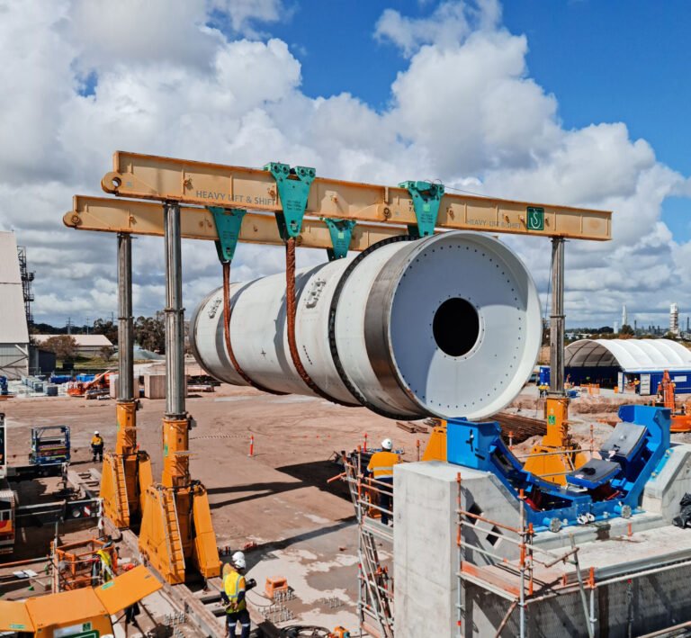


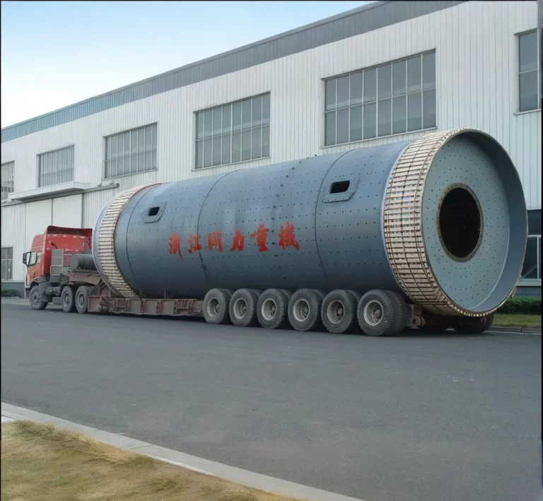

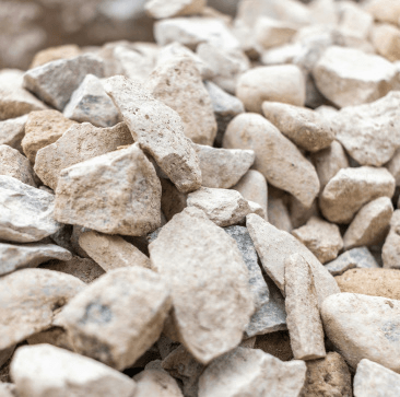
Mainly used for grinding finished products and raw materials in cement plants, and also suitable for grinding various ores and other grindable materials in metallurgy, chemical industry, power and other industrial and mining enterprises. It is one of the key equipment in the cement production process. By grinding the cement raw materials to achieve a certain fineness and uniformity, it provides qualified raw materials for the subsequent cement production process.

In cement production, rotary kiln is one of the key equipment, used to calcine cement clinker. The large gear of the ball mill can be used in the transmission system of the rotary kiln to help drive the kiln body to rotate, so that the material can be evenly heated in the kiln, a series of physical and chemical reactions occur, and finally high-quality cement clinker is formed.
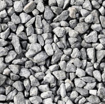
generally suitable for product trial production and intermittent small-batch production, mainly used for material mixing and grinding, which can make the product fineness uniform and save power. It is suitable for the mixing and grinding of ordinary and special materials. Its structure is divided into integral type and independent type, with the characteristics of low investment, energy saving and power saving, simple operation, stable and reliable performance.

Mainly used to calcine limestone to produce lime. Similar to cement rotary kiln, the ball mill gear can be used as a transmission component to provide stable power for the lime rotary kiln, ensuring that the kiln body rotates at a certain speed, so that the limestone can decompose and react at a suitable temperature and atmosphere to produce lime products that meet the requirements.
Commonly used to dry various wet materials, such as coal, ore, clay, etc. The ball mill gear can be installed on the cylinder of the rotary dryer. By driving the cylinder to rotate, the material can be continuously rolled in the cylinder and fully contacted with the hot air flow, thereby achieving efficient drying, improving the dryness of the material, and meeting the requirements of subsequent production processes.

Generally used to cool high-temperature materials. The ball mill gear can be used as the transmission device of the drum cooler to drive the cooler drum to rotate, so that the high-temperature material moves slowly in the drum, and at the same time exchanges heat with the cold air or other cooling media to achieve rapid cooling of the material, which is convenient for subsequent storage, transportation and processing.
With the improvement of environmental protection requirements, waste incineration treatment has received more and more attention. The garbage incineration rotary kiln is used to incinerate urban garbage and other wastes. The large gear of the ball mill can be used as its transmission component to drive the kiln body to rotate, so that the garbage can be fully burned in the kiln to achieve harmless and reduced treatment. At the same time, the heat generated can be used for power generation or heating.
During the ore processing, it is used to roast the ore to change the physical and chemical properties of the ore, which is convenient for subsequent mineral processing and smelting. The ball mill gear can be used in the transmission system of the ore roasting furnace to drive the furnace body to rotate, so that the ore is evenly heated in the furnace, a roasting reaction occurs, and the selectivity and smelting efficiency of the ore are improved.
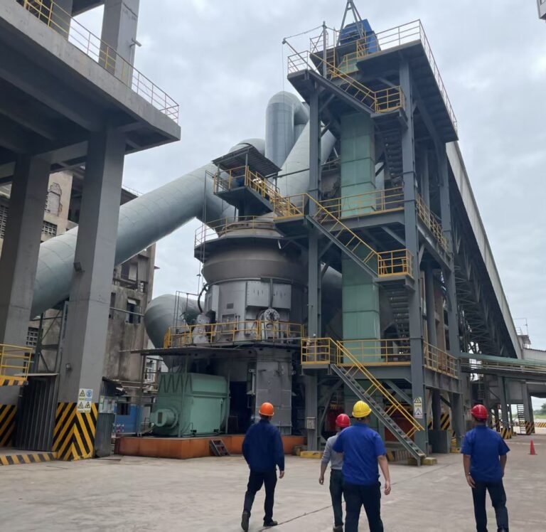
Raw Milling For Cement Meal and Clinker Grinding Plant: Ball mill Vs Vertical roller mill
Advanced mill technology for the grinding of cement raw meal and cement clinker for use in high-grade building materials.
February 19, 2025
Maerz Vertical Calcination Lime Kiln Double Chamber Shaft HPS Operation
Discover the Maerz Vertical Calcination Lime Kiln with double chamber shaft and HPS operation. Efficient, high-performance lime production.
March 08, 2025

Understanding GGBS Production Lines: Essential Equipment, Benefits and Investment Insights
A GGBFS production line transforms blast furnace slag, a byproduct of steel production, into finely ground granulated slag.
February 07, 2025
You can get in touch with us through the following contact information
AddressNo. 2289 Huancheng South Road, Tongxiang, Jiaxing, Zhejiang Province, China. Zip code:314500
Please fill in the sales inquiry form and our sales representatives will be in touch shortly.