


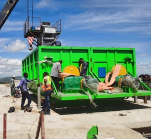


How to replace the vertical roller mill grinding tyre
Vertical roller mill grinding roller replacement is carried out by sequential mechanical disassembly and hydraulic extraction of the roller assembly and roller tyre. The operation starts from the mill inspection door, where hydraulic cylinders and lifting devices are installed to support and control the roller movement. The connection bolts between the grinding roller and rocker arm are then loosened and removed, allowing the roller to be turned out to the maintenance position. After the roller is positioned outside the mill, the clamping blocks and fastening bolts connecting the roller tyre to the roller hub are dismantled. Dedicated grinding roller dismantling tools are installed, and hydraulic force is applied to push the roller tyre off the hub. Depending on inspection results, the roller hub and bearings are either overhauled or replaced. Once bearing installation and hub assembly are completed, the roller is reinstalled onto the roller seat. The new roller tyre is then mounted and secured according to specified tightening torque and assembly clearances. All components are aligned and fixed in the prescribed order to ensure proper load distribution and operational reliability. So in this article we will walk you through step by step how to replace the grinding roller liner.
Flsmidth OK Mill Veritcal Raw mill grinding roller segmented liner replacement video:
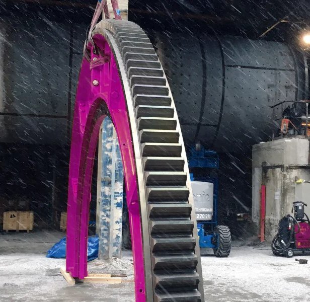
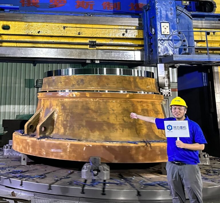
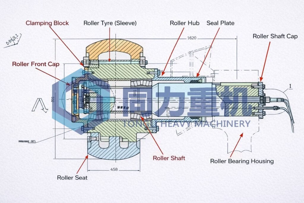
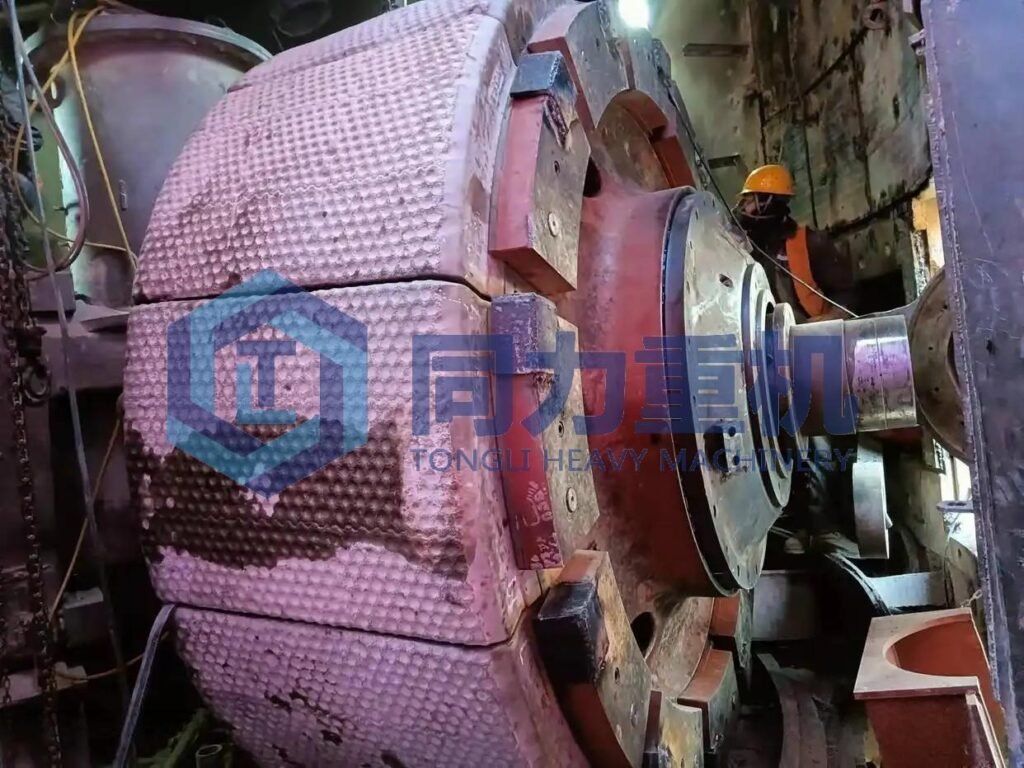
The structure of the veritcal roller mill grinding roller
Disassembling the inspection door and installing the hydraulic cylinder:
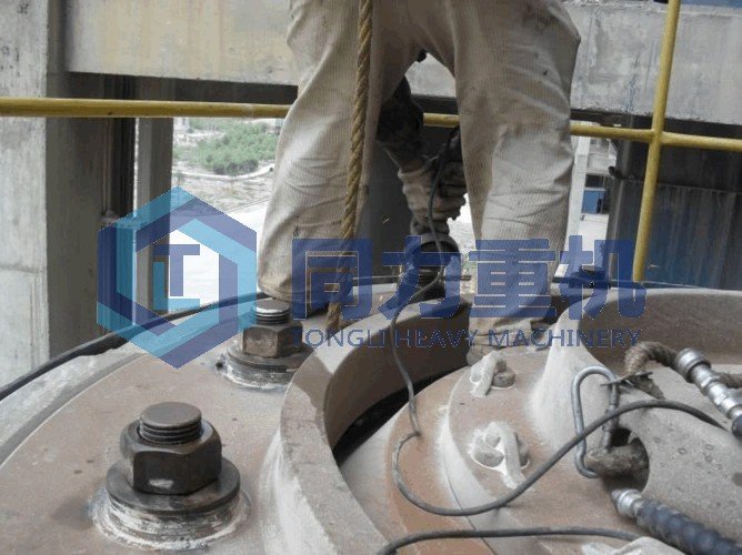
Step 1: Disassembly of the access door and installation of the hydraulic cylinder:
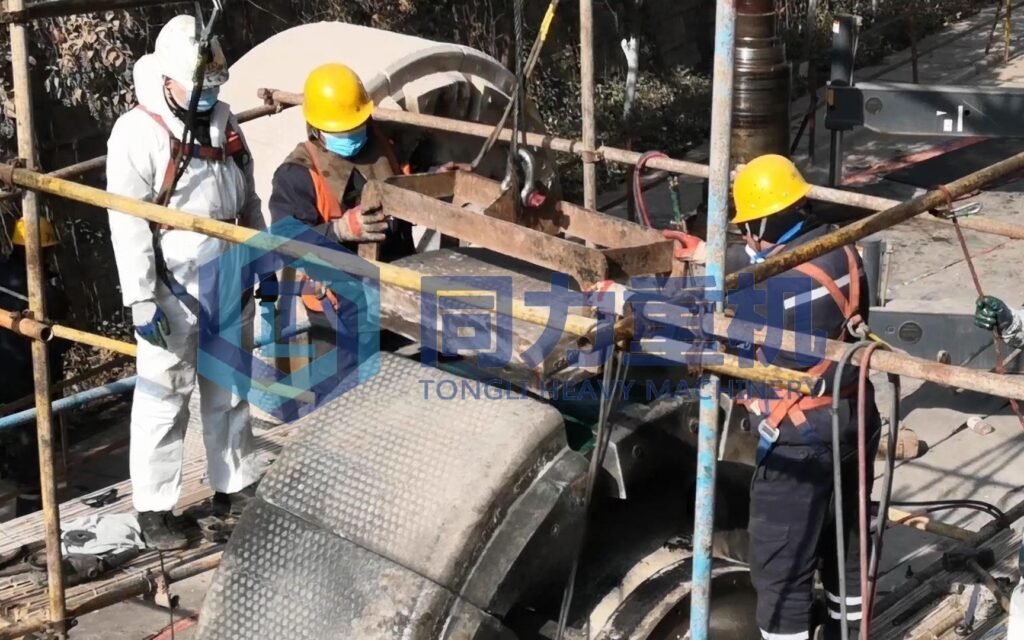
Use an electric impact wrench to remove the bolts of the grinding roller inspection door. During removal, two 1-ton manual chain hoists shall be used to secure the inspection door and the VRM mill casing to prevent the door from suddenly falling out when released. A 25-ton mobile crane, together with φ10 mm steel wire rope and shackles, shall then be used to lift and remove the inspection door.
- Remove the pin shaft of the hydraulic cylinder spherical (articulated) bearing. With the assistance of a 25-ton crane, install the lower articulated bearing pin of the hydraulic cylinder.
- Afterwards, connect and start the hydraulic power unit (HPU), slowly extend the hydraulic piston rod, align it with the upper hydraulic pull-rod bracket, and install the articulated bearing pin.
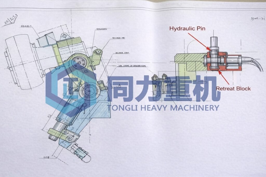
Step 2: Removal of the Connection Bolts Between the Grinding Roller and Rocker Arm
Fabricate a T-shaped special tool and use two 50-ton hydraulic jacks to extract the taper pins and withdrawal sleeves connecting the grinding roller to the rocker arm on both sides.
After one taper pin has been removed, the remaining taper pins and withdrawal sleeves may be loosened and removed by auxiliary knocking using a φ60 × 2500 mm steel pipe and sledgehammer.
Heating methods may also be applied as an auxiliary measure to facilitate disassembly if required.
Step 3: Swinging (Tilting) the Grinding Rollers Out of the Mill
By operating the hydraulic power unit, swing two diagonally positioned grinding rollers out of the mill housing. Carefully control the roller tilting speed to prevent excessive movement, which could otherwise cause damage to the hydraulic cylinders.
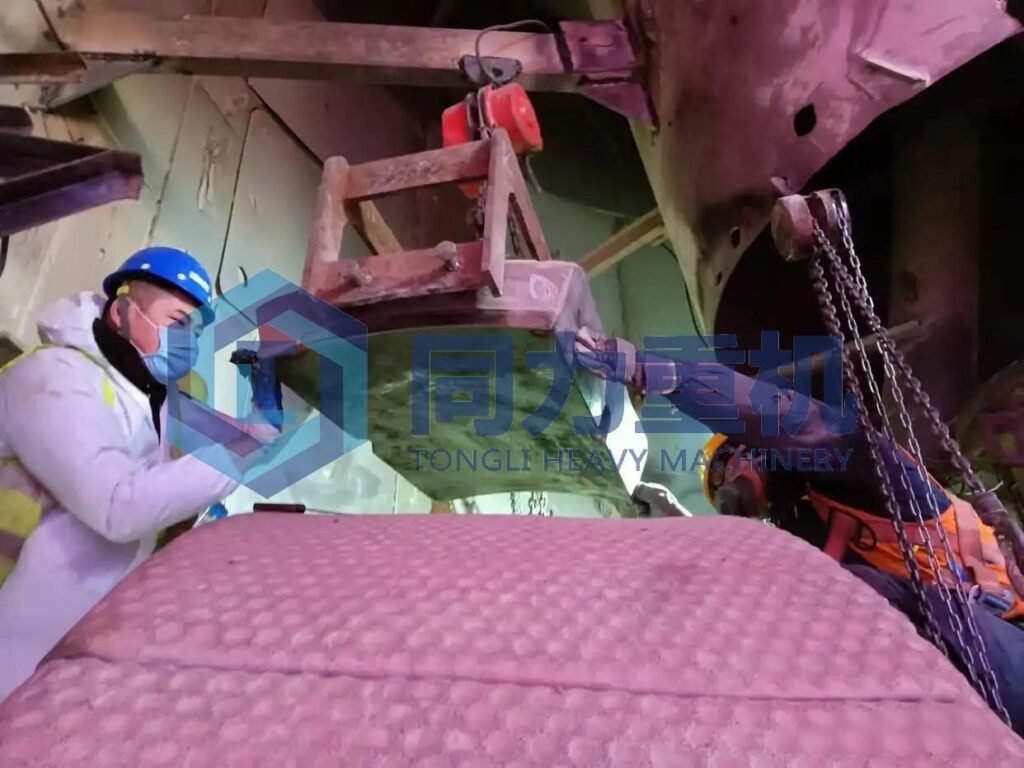
Step 4: Removal of Clamping Blocks and Bolts Connecting the Roller Tyre to the Roller Hub
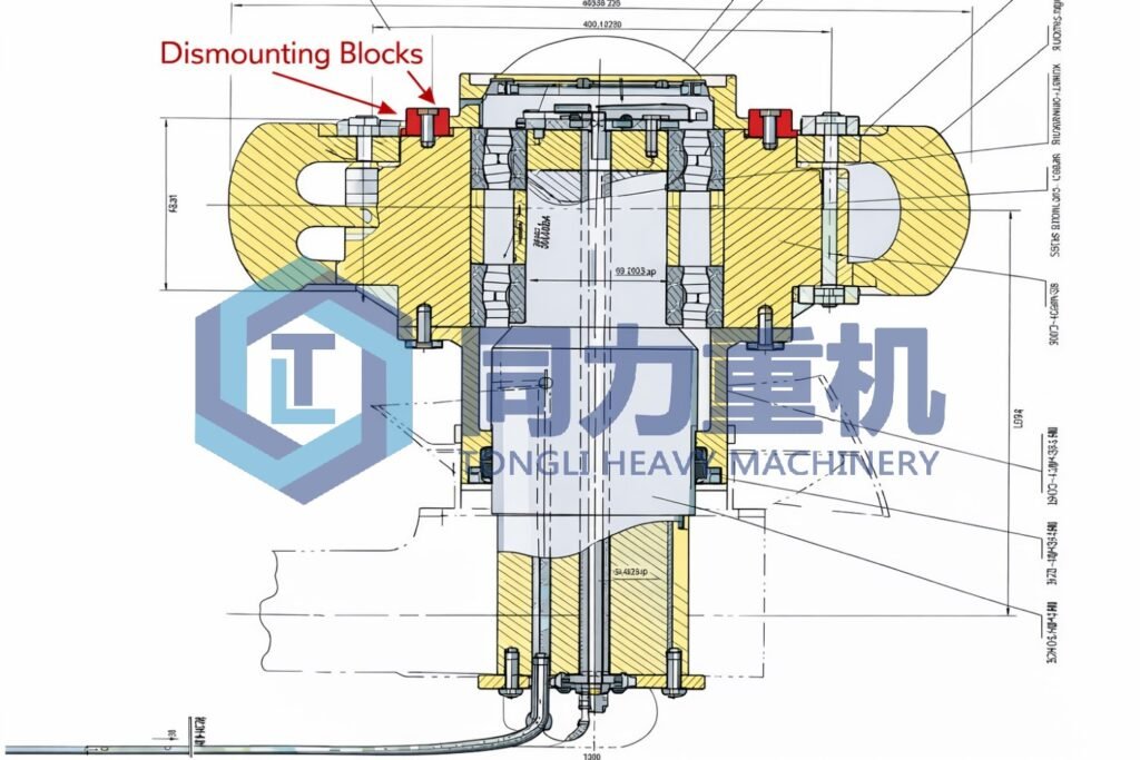
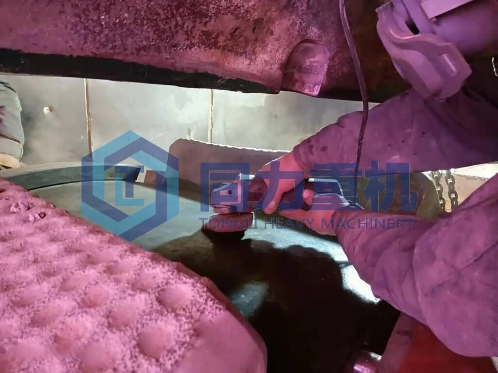
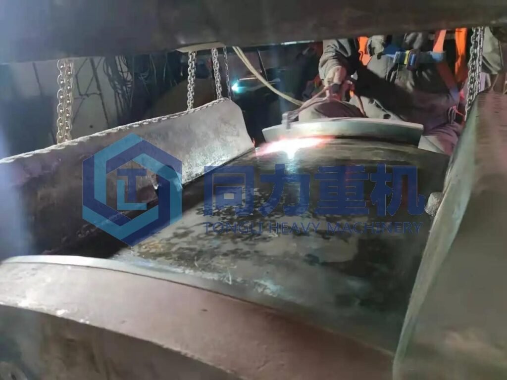
Use a 100-type oxy-fuel cutting torch to cut off the bolts connecting the roller tyre (sleeve) to the roller hub (roller core). Fabricate a T-shaped special tool and use two 50-ton screw jacks, together with sledgehammer impact, while a crane assists in removing the roller tyre clamping blocks. Before removal, the clamping blocks shall be clearly marked in sequence to avoid incorrect reassembly, which could lead to misalignment or bolt-hole mismatch during installation.
Step 5: Installation of Grinding Roller Dismantling Tools
Erect the required scaffolding, and fabricate a roller tyre dismantling platform using 30 mm thick steel plate. The dismantling platform shall be directly welded to the sealing grooves on both sides of the grinding roller. The distance between the dismantling platform and the roller tyre shall correspond to the working height of the 100-ton hydraulic jacks. At ground level, a φ120 mm steel pipe shall be used to directly support the bottom of the dismantling platform.
Step 6: Jacking Out the Roller Tyre
Install two 100-ton hydraulic jacks between the dismantling platform and the roller tyre.
Start the hydraulic jack power unit and apply pressure; when the pressure reaches approximately 120 MPa, the roller tyre can be pushed off. If separation is difficult, localized heating of the roller tyre may be applied as an auxiliary method. After removal, fabricate four roller tyre lifting hooks (note: the inner curvature of the hooks must match the outer curvature of the roller tyre). Use a 25-ton crane to lift down the worn roller tyre (approximate weight: 4 tons).
Step 7: Disassembly and Installation of Roller Core and Bearings:
- Disassemble the grinding roller shaft and the rear end cover of the roller seat, disassemble the front end cover of the grinding roller, the inner ring cover of the bearing, and the internal lubrication pipe of the roller core;
- Install two 50T thin oil jacks on the disassembly platform, pull the roller core, bearings, and grinding roller shaft out of the grinding roller seat as a whole, and lower them using a 25T crane;
- Disassemble the roller core, bearings, and grinding roller shaft: Remove the outer ring covers of the bearings at both ends of the roller core, vertically lift the grinding roller shaft, and the roller shaft with bearings can be separated from the roller core (the bearings and roller core are clearance fit), then make tools and oil jacks to pull out the grinding roller bearings;
- Assemble the roller core, bearings, and grinding roller shaft: Clean the grinding roller shaft, then install the two sets of grinding roller bearings onto the grinding roller shaft; install the outer ring end cover of the outer bearing of the roller core onto the roller core, place the roller hub horizontally, vertically lift the grinding roller shaft with bearings and place it into the roller core, then install the outer ring end cover of the inner bearing. Before installation, the clearance, inner and outer ring dimensions, inner ring of the roller hub, and diameter of the roller shaft of the new bearing should be measured; if the interference fit is too large, it should be installed by heat fitting(shrink on) method.
Step 8: Install the grinding roller onto the roller holder:
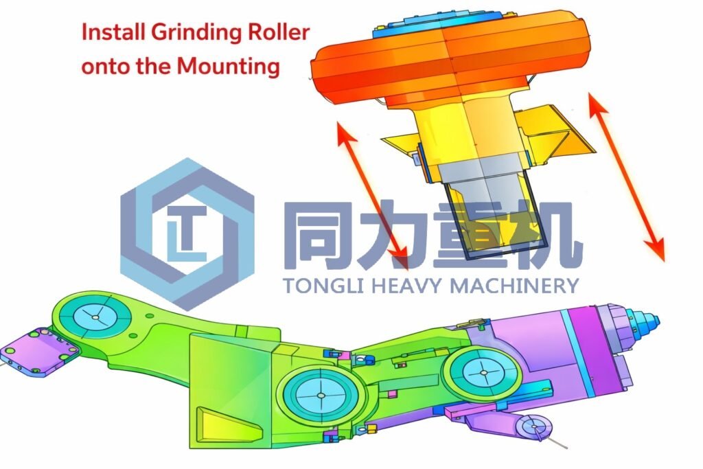
Use a 25T crane to vertically lift the grinding roller and slowly place it into the roller holder (the grinding roller shaft and roller holder are keyed together). Install the rear end cap of the grinding roller shaft and tighten the grinding roller shaft.
Step 9: Install the new roller sleeve:
Use a 25T crane to lift the new roller sleeve (5T) horizontally and place it inside the roller core. Then, use two 16T auger jacks to level the roller sleeve. Install the roller sleeve clamping block by striking it with a sledgehammer and tightening the roller sleeve bolts. The clamping block should be flush with the surface of the roller core.
Step 10: Disassemble the roller sleeve, disassemble the platform, and install other components:
Step 11: Turn the grinding roller back and disassemble the hydraulic cylinder.
Step 12: Close the grinding door and test the machine.
Another option would be rebuilding the grinding roller instead of replacing the tyre and that applies to the steel casting + hard facing grinding roller, and this is usually done inside of the grinding chamber instead taken the whole assembly out, it is called In Situ On-site Hardfacing Service.
Is the installation process for segmented ceramic grinding roller liners the same as for a one-piece roller tyre?
No, the most fundamental difference lies in how the wear parts are mounted onto the roller core. A segmented ceramic grinding roller liner is installed piece by piece, with each individual segment positioned, aligned, and mechanically fixed. In contrast, a one-piece roller tyre is installed as a single unit and relies on high-temperature hot fitting, where thermal expansion allows the tyre to slide onto the roller core before cooling and locking in place.
How is a one-piece grinding roller tire installed, and why is high-temperature anti-seize compound required?
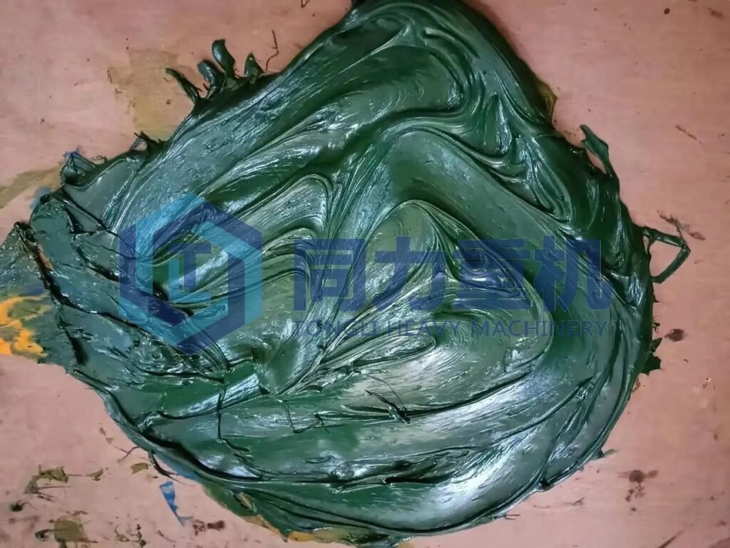
A one-piece roller tyre requires the tyre to be heated typically to 150–300 °C to achieve sufficient thermal expansion for installation. During this process, a high-temperature anti-seize or assembly compound is applied to the contact surfaces between the tyre and the roller core. This compound prevents metal-to-metal adhesion, galling, or seizure during heating, sliding, and cooling, and it also facilitates future disassembly. Without this compound, the The tire may bond to the roller core, making removal extremely difficult and increasing the risk of damage.
How are segmented ceramic grinding roller liners installed step by step?
Installation begins with surface preparation of the roller core, followed by the placement of the first reference segment. Each ceramic liner segment is then installed individually, with careful control of axial position, radial alignment, and segment-to-segment gaps. Temporary tightening is used initially, allowing fine adjustment before final torque is applied. This piece-by-piece process continues circumferentially until the full roller surface is covered.
Why is installation accuracy more critical for segmented ceramic liners?
Because segmented ceramic liners are rigid and highly wear-resistant, they cannot self-correct under load. Any misalignment between segments—such as uneven height, incorrect curvature matching, or inconsistent gap spacing—will cause localized stress concentration. Unlike a one-piece tyre, which forms a continuous grinding surface after cooling, segmented liners depend entirely on installation precision to ensure uniform load distribution during mill operation.
How are segmented ceramic liners fixed and secured after positioning?
Once all segments are correctly positioned, the mechanical fixing system is tightened in a specified sequence and in multiple stages. Final tightening is performed using calibrated torque tools to ensure uniform clamping force. This controlled tightening process is essential to prevent liner cracking, bolt loosening, or segment movement during operation.
How does this installation difference affect maintenance and future replacement?
One-piece roller tyres, due to hot fitting and metal bonding, often require reheating and heavy equipment for removal. In contrast, segmented ceramic liners can be replaced locally, allowing individual worn or damaged segments to be removed without dismantling the entire roller. This reduces maintenance time, lowers labor intensity, and minimizes mill downtime—provided the original installation was done correctly.
In summary, the installation difference can be distilled into two core points: segmented ceramic liners are installed piece by piece without high-temperature anti-seize compounds, while one-piece roller tyres require hot fitting with high-temperature assembly compounds. These differences define not only the installation process, but also the precision requirements, maintenance strategy, and long-term operational reliability of the vertical roller mill.
High-Temperature Anti-Seize Compound for Segmented VRM Grinding Roller Liners
Before installing segmented (split-type) grinding roller liners / tyres in a vertical roller mill (VRM), it is mandatory to apply a high-temperature anti-seize assembly compound to the contact surfaces between the liner segments and the roller core. This compound plays a critical role in ensuring safe installation, stable operation, and future dismantling of the grinding roller assembly under high load, high temperature, and vibration conditions.
Problems Addressed by Anti-Seize Application
Without proper anti-seize treatment, segmented roller liners are prone to the following failures:
- Seizure and galling caused by high contact pressure and thermal expansion
- Fretting wear at the liner–core interface due to micro-movements during mill operation
- Corrosion bonding between mating surfaces in high-humidity or dusty environments
- Difficult or destructive disassembly, often resulting in damage to the roller core during liner replacement
The use of anti-seize compound effectively eliminates these risks.
Typical Composition and Performance Requirements
A VRM-grade anti-seize compound typically consists of:
- Solid lubricants: copper-, nickel-, or molybdenum-disulfide (MoS₂)-based particles
- High-temperature carrier: synthetic or mineral oil designed to resist evaporation
- Anti-oxidation and anti-corrosion additives
Recommended performance characteristics:
| Parameter | Typical Requirement |
| Continuous temperature resistance | ≥ 1,000°C |
| Load-carrying capacity | Suitable for heavy static interference fits |
| Resistance to fretting wear | Excellent |
| Chemical stability | Non-carbonizing, non-hardening |
| Compatibility | Safe for steel–steel contact |
Application Areas on Segmented Roller Liners
Anti-seize compound must be applied only to specific mating surfaces, as shown below:
| Application Location | Function |
| Inner arc surface of liner segments | Prevent seizure during thermal expansion |
| Roller core outer surface | Reduce friction during assembly |
| Segment-to-segment contact faces | Minimize fretting and vibration wear |
| Locating keys and keyways | Prevent key seizure |
| Non-threaded bolt contact surfaces | Corrosion protection |
Application Method and Thickness Control
Correct application is as important as selecting the compound itself:
- Clean all contact surfaces to Sa 2.5 standard before application
- Apply a thin, uniform layer (typically 20–50 μm) using a brush or roller
- Avoid excessive coating thickness, which may affect liner fit-up and concentricity
- Assemble liners immediately after application to prevent contamination
VRM Grinding Table Liner Maintenance Procedure
Step 1: Removal of Inner Ring Liner Clamping Blocks
Fabricate a T-shaped special tool and use two 50-ton hydraulic jacks, with auxiliary sledgehammer impact, to remove the inner ring liner clamping blocks.
Step: 2 Gouging Around the Liner Plate
Use carbon arc air gouging to gouge around the perimeter of the grinding table liner plate in order to reduce the bonding force between the liner plate and the grinding table (grinding disc).
Additionally, gouge notches on both sides of the liner plate to facilitate subsequent removal.
Step 3: Removal of the Liner Plate
Fabricate an S-shaped special tool. Hook one end onto the liner plate and install a 50-ton hydraulic jack on the opposite side to push the liner plate out. For the remaining liner plates, apply the same method with the assistance of two 1000-mm pry bars to complete removal.
Step 4: Cleaning of New Liner Plates and Grinding Table
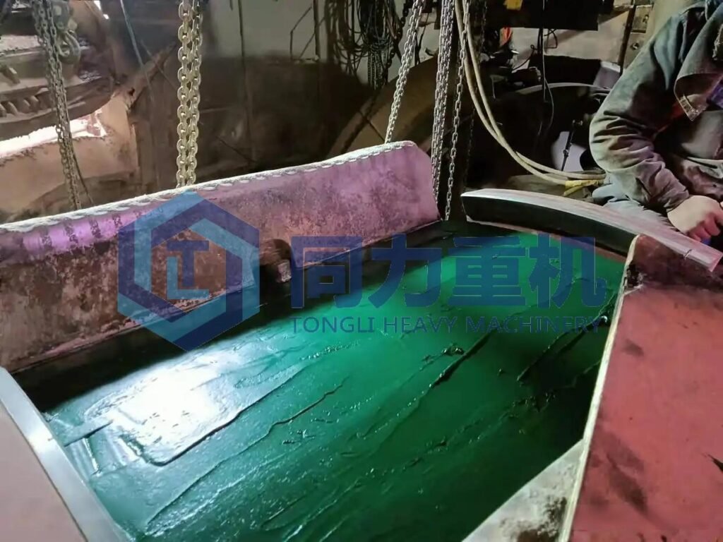
Use a grinding/polishing machine to remove burrs from the bottom surface of the new liner plates, and measure and record the height on both sides of each liner plate. Clean burrs and residual material from the grinding table surface using a polishing machine to ensure proper seating.
Step 5: Installation of New Liner Plates
Use a 25-ton mobile crane and lifting slings to hoist each new liner plate into the mill and install them sequentially according to the recorded height measurements:
- The height difference between adjacent liner plates shall not exceed 5 mm.
- The height at the contact surfaces of two adjacent liner plates shall transition from higher to lower in accordance with the rotation direction of the grinding table.
- The gaps between liner plates shall be uniform and consistent.
- The outer ring of the liner plates shall be tightly fitted against the outer edge of the grinding table. After installation, there shall be no looseness or rocking.
- The gaps between liner plates, between liner plates and the grinding table, and between clamping blocks shall be tightly packed with oil-impregnated asbestos packing.
Step 6: Installation of Liner Clamping Blocks
Tighten the liner clamping block bolts, using a sledgehammer for auxiliary seating if necessary. After installation, the height of the clamping blocks shall not exceed the height of the liner plates.
FAQ: What are the commonly asked question about Vertical Roller Mill tyre replacement and maintenance?
Yes, in some VRM models, grinding roller tyres can be replaced without removing the whole roller. This is only possible when the mill uses a split-type tyre or a hydraulic clamping design and there is enough clearance between the tyre and roller core. Before replacement, the interference fit and roller core condition must be checked. During installation, the tyre is heated, removed with hydraulic tools, and the new tyre is installed with strict alignment control.
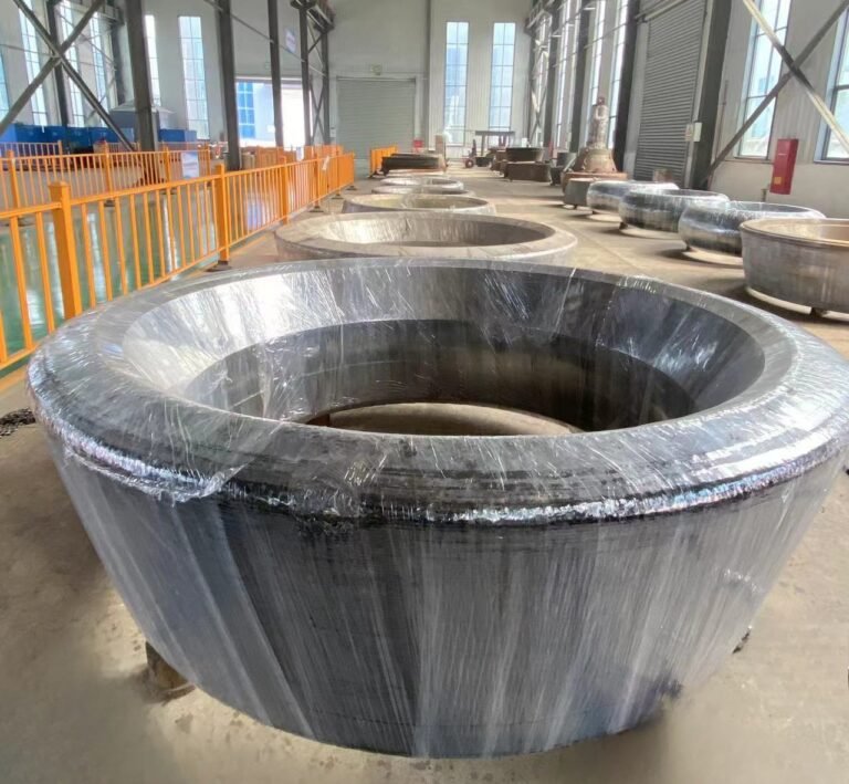
In vertical roller mills (VRMs), grinding roller tyres, roller sleeves, and roller liners are different wear parts:
Grinding roller tyres are thick, load-bearing components mounted on the roller core. They directly contact the material and perform grinding, with high hardness and impact resistance.
Roller sleeves are thinner intermediate wear layers installed on the roller core, used to protect the core and provide a replaceable mounting surface for the tyre.
Roller liners are segmented wear plates fixed by bolts or welding. They are not main load-bearing parts and are used to reduce local wear and extend roller service life.
One-piece grinding roller tyres are integral thick-walled cylindrical components, usually installed on the roller core with an interference fit. During replacement, the tyre must be uniformly heated (by induction or flame heating) to expand the bore, then removed using hydraulic push–pull devices. The new tyre is heated to the specified temperature and mounted at the designated position on the roller core; after cooling, a secure interference fit is formed. This process requires strict control of heating temperature, heating uniformity, and assembly concentricity, and typically the entire roller assembly must be removed and serviced at a dedicated workshop.
Segmented grinding roller tyres consist of 2–4 arc-shaped segments fixed to the roller core by high-strength bolts or hydraulic clamping systems. Replacement can be carried out on-site without removing the roller assembly or heating the tyre as a whole. The worn segments are removed individually, and new segments are installed according to alignment marks and tightened to the specified torque. This method is faster and more convenient, but precise control of segment gaps and axial alignment is essential to prevent uneven wear or vibration during operation.
It depends on the wear severity, material, and structural integrity of the roller hub. In short: welding repair is suitable for light to medium wear on weldable hubs; severely worn or cracked hubs must be replaced.
Welding repair is acceptable when wear is local and moderate (minor scoring or small-area spalling), with no cracks, no keyway deformation, and remaining wall thickness ≥ 70% of the design value. The hub material must be weldable (e.g. medium-carbon or low-alloy steel). Repair is typically done by wear-resistant weld buildup, followed by stress relief and precision machining to restore the fit with the roller tyre.
Replacement is mandatory when the hub shows through cracks, severe wear, remaining wall thickness < 60%, excessive deformation of mounting reference surfaces, or when the material has poor weldability (e.g. high-carbon steel or cast iron). In such cases, welding cannot ensure structural safety under high load and may lead to tyre loosening or failure.
No, bearings do not have to be replaced every time a grinding roller tyre is changed. The decision should be based on bearing condition, operating hours, and disassembly conditions.
Bearings may be reused if they have operated smoothly during the tyre service life, with no abnormal noise, excessive temperature rise, or vibration, and post-disassembly inspection shows no pitting, spalling, cracks, or abnormal wear on the raceways and rolling elements. If seals are intact and grease is not degraded or emulsified, cleaning and re-greasing with suitable high-temperature grease is sufficient.
Bearings should be replaced if they have reached or are close to their design life (typically 8,000–12,000 hours for VRM roller bearings), show fatigue damage, excessive clearance, contamination, or if they were impacted or polluted during tyre replacement. Preventive replacement is also recommended when tyre replacement involves heating of bearing housings or heavy pulling forces, as these can cause hidden internal bearing damage.
In short: bearing replacement during roller tyre change is condition-based; reuse is acceptable for healthy bearings, while worn, aged, or potentially damaged bearings should be replaced to ensure safe and stable operation.
Yes. Mismatched liner and roller tyre materials are a common cause of abnormal wear in VRM mills, often leading to significantly accelerated wear rates. The root cause is an unbalanced hardness difference and incompatible wear mechanisms, which disrupt the normal “mutual wear adaptation” between the grinding table liner and the roller tyre. From an engineering standpoint, the hardness difference between liner and tyre should be controlled within a reasonable range, typically 2–5 HRC.
If the roller tyre is much harder (e.g. high-chrome cast iron at 62–65 HRC) while the liner is relatively soft (e.g. 55–58 HRC), the liner will suffer severe ploughing and cutting wear, and its service life may be reduced by 30–50%.
If the liner is harder than the tyre, the tyre surface may develop deep grooves, fatigue spalling, or even local breakage. Beyond hardness, the wear mechanisms must also be compatible. For example, when impact- and abrasion-resistant alloy tyres are paired with liners of poor abrasion resistance, adhesive wear can occur. The generated metal debris may contaminate the material and further accelerate secondary wear of both components. Field experience confirms this effect: in one VRM application, a hardness mismatch of 7 HRC (tyre 63 HRC vs. liner 56 HRC) reduced liner life to ~2,000 hours compared with a design life of 5,000 hours, and increased mill vibration from 2.5 mm/s to 5.8 mm/s. After switching to a matched alloy liner (~60 HRC), liner life returned to the design level and roller tyre wear rate dropped by about 40%.
In short: liner and roller tyre materials must be selected as a matched system. Excessive hardness mismatch or incompatible wear mechanisms will inevitably cause abnormal wear and reduced mill stability. For more details about vertical roller mill wear please check out this article: "What casues wear to the vertical roller mill grinding roller"
During grinding roller maintenance, the most frequently observed bearing failures are closely related to heavy load, elevated temperature, inadequate lubrication, and assembly deviations. The first is rolling element and raceway pitting and spalling, a typical fatigue failure under long-term alternating loads, characterized by dense micropits on the raceway that may develop into large-area flaking. The second is wear and thermal smearing (scuffing) of the inner and outer rings, usually caused by degraded or dried-up grease and contamination ingress, which increase frictional heat and may even produce metal adhesion marks. The third is cage fracture or deformation, commonly resulting from insufficient internal clearance, impact loading during operation, or excessive assembly misalignment that causes the rolling elements to overload and crush the cage. Another frequent issue is corrosion induced by seal failure, where dust or slurry enters the bearing chamber and mixes with lubricant, accelerating corrosion, particularly under humid operating conditions. Finally, creep or fretting between the bearing inner ring and the shaft journal may occur due to insufficient interference fit or inadequate preload, producing polished areas or even circumferential grooves on the journal surface.
What is the typical replacement interval for a vertical roller mill grinding roller tyre?
There is no fixed replacement interval for a vertical roller mill (VRM) grinding roller tyre. In industry practice, the typical service life ranges from 4,000 to 12,000 hours, depending on material properties, operating conditions, and tyre design. Typical ranges by application
- Highly abrasive materials (e.g. quartz-rich feed, granite): 4,000–6,000 h
- Cement clinker / limestone: 8,000–12,000 h
- Coal grinding: up to 10,000–15,000 h under stable conditions
Key factors influencing replacement interval
- Material abrasiveness: high-silica or hard feed accelerates abrasive wear.
- Tire material and hardness: high-chrome cast iron or hardfaced alloy tyres (58–65 HRC) typically last 30–50% longer than conventional alloy steel tyres; hardfaced carbide tyres can reach 10,000–12,000 h in clinker grinding.
- Operating conditions: grinding pressure exceeding design values by >10% or uneven tyre–table gap can shorten tire life by 20–30%, while stable operation significantly extends service life.
Replacement criteria (industry practice)
Tyres are replaced based on measured wear, not hours alone. Common limits are:
- Diameter reduction of 3–5% of the original size
- Deep grooves (>5 mm), large-area spalling, or cracking
Exceeding these limits often leads to excessive vibration and reduced grinding efficiency.
In short: VRM grinding roller tyres typically last 4,000–12,000 hours, but replacement should be decided by wear condition and operating stability, not time alone.
What lifting and hydraulic tools are required to replace a VRM roller tyre?
Replacing a VRM grinding roller tyre requires dedicated lifting equipment and high-capacity hydraulic tools, selected according to tyre design (one-piece or segmented) and weight.
Lifting equipment
- Dedicated balancing lifting beam: Custom-designed to match tire diameter and lifting points, with a load capacity ≥ 1.5 × tire weight. It maintains concentricity during lifting and prevents impact to the roller core or bearings. For one-piece tires > 5 t, use an electric hoist or overhead crane with a controlled lifting speed of 0.5–1 m/min.
- Adjustable turning / tilting lifting device (segmented tires): Used for arc-shaped segments, with an adjustable angle range of 0°–90°, ensuring accurate fit to the roller core curvature during installation.
Hydraulic tools
- Hydraulic push–puller (hydraulic puller): The key tool for removing one-piece, interference-fit tyres. Required pushing force typically ranges from 50 to 200 t, depending on tire size and interference. It is used together with induction or flame heating to remove the tire under thermal expansion.
- Hydraulic bolt tensioners (segmented tires): Matched to high-strength bolts (e.g. M48, M64). Tensioning force should reach ~1.2 × the required bolt preload to ensure segment clamping and concentricity. Final tightening is verified with a digital torque wrench, with torque deviation controlled within ±3%.
- Synchronous hydraulic jacks: Used to lift and position the roller assembly. Height deviation between jacks should be ≤ 0.5 mm to avoid assembly misalignment. Each jack should have a capacity ≥ 1.2 × the supported load.
Auxiliary hydraulic equipment
- Hydraulic power unit: Pressure rating 30–63 MPa, adjustable flow 1–5 L/min, suitable for different hydraulic tools.
- Hydraulic grease gun: Used to apply high-temperature anti-seize or lubricating grease on the mating surfaces. Injection pressure ≥ 15 MPa ensures uniform coverage.
What are the common installation errors during grinding roller tyre replacement?
Most installation errors during grinding roller tyre replacement fall into three critical areas: fit accuracy, positioning/alignment, and assembly process control. These errors often lead to uneven wear, excessive vibration, or early failure.
Fit surface preparation and lubrication errors
- Poor cleaning of mating surfaces (roller core and tire bore), with remaining scale, rust, or debris, can reduce effective interference and cause tire slippage or axial movement during operation.
- Incorrect or uneven application of high-temperature anti-seize grease may lead to uneven stress distribution after cooling and initiate local cracking.
- Good practice: mating surfaces cleaned to Sa 2.5, grease layer controlled at 0.05–0.1 mm.
Heating temperature and uniformity errors (one-piece tires)
- Overheating beyond the specified range (typically 150–200 °C, material-dependent) can degrade microstructure and reduce hardness.
- Uneven heating causes non-uniform bore expansion, leading to forced assembly and high residual stress.
- Requirement: temperature variation during heating controlled within ±10 °C.
Alignment and positioning errors
- Misalignment with locating keys or shoulders results in excessive radial runout and uneven load distribution.
- Axial positioning errors can cause uneven clearances to bearing housings and axial movement during operation.
- Typical limit: radial concentricity deviation ≤ 0.05 mm.
Segmented tire assembly and tightening errors
- Excessive segment gaps (> 0.1 mm) or step mismatch between segments lead to stress concentration and edge chipping.
- Insufficient or uneven bolt preload, often due to incorrect hydraulic tensioning, causes segment loosening and uneven wear.
- Good practice: bolt preload at 70–80% of yield strength, preload deviation within ±5%.
Skipping no-load run-in
Directly loading the mill after installation without a no-load run-in prevents uniform contact formation between tyre and table liner. Recommended practice: 4–8 hours of no-load running before full operation to avoid early pitting or groove wear. most installation failures are caused by poor surface preparation, improper heating, misalignment, incorrect fastening, and skipping run-in procedures. Strict control of these parameters is essential for stable VRM operation and full tyre service life.
How to check wear limits of a VRM grinding roller tyre before replacement?
Using a laser diameter gauge or micrometer, select 8–12 evenly distributed measurement points around the tyre circumference to measure the outer diameter, wear band width, and wall thickness. Compare the measured values with the original design dimensions to calculate wear. Industry-accepted replacement limits are:
- Outer diameter reduction of 3–5% of the original diameter, or
- Remaining wall thickness below 60% of the design value
At this stage, the wear-resistant layer is essentially consumed and the tyre must be replaced.
For segmented roller tyres, the segment joint gaps shall also be measured; gaps exceeding 0.2 mm may induce operational vibration and require replacement.
Surface damage inspection
Conduct magnetic particle testing (MT) or dye penetrant testing (PT) on the tyre surface and edges. Replacement is required if any of the following are detected, even if dimensional wear has not reached the limit:
- Grooves deeper than 5 mm
- Radial cracks longer than 100 mm
- Large-area flaking or spalling
- Dense fatigue pitting on the surface
Surface wear uniformity shall also be assessed. If one-sided wear exceeds 40% of the total wear, the roller system alignment should be investigated before replacing the tyre.
Operating parameter–based evaluation
Review mill operating records. The roller tyre is considered to have reached its wear limit and should be replaced if:
- Mill vibration remains above 8 mm/s,
- Grinding efficiency decreases by more than 10%, or
- Specific power consumption increases by more than 15%,
- after excluding other influencing factors such as feed material variation or grinding table liner wear.
In summary: VRM grinding roller tyre replacement should be determined by measured wear, surface integrity, and operating performance, rather than by operating hours alone.
How does incorrect tyre installation affect VRM vibration and power consumption?
Impact on mill vibration
If the roller tyre concentricity deviation exceeds 0.05 mm during installation, or if uneven heating of a one-piece tyre introduces residual stress after mounting, the effective contact area between the roller tyre and the grinding table liner is reduced and the contact stress becomes uneven. During operation, the roller system will exhibit periodic radial runout, causing reminder? sorry fix: leading to a periodic radial runout of the roller assembly. As a result, the mill casing vibration level may increase from a normal 2–4 mm/s to above 8 mm/s. For segmented roller tyres, segment joint gaps exceeding 0.1 mm, bolt preload deviation greater than ±5%, or axial step mismatch between segments can create local stress concentration points, generating high-frequency impact vibration. In severe cases, this may cause segment loosening or edge chipping, further aggravating the vibration level. In addition, improper axial positioning of the roller tyre can cause axial movement, which superimposes on radial vibration and leads to combined vibration faults during mill operation.
Impact on grinding power consumption
Improper installation resulting in non-uniform tyre–table contact causes uneven pressure distribution on the grinding bed. Over-pressurized zones tend to form dense material cakes, while under-pressurized zones cannot achieve effective grinding. Consequently, the mill consumes additional power to break down compacted material and recirculate coarse particles. Meanwhile, increased vibration raises mechanical energy losses in the drive system and increases friction in bearings and seals. Industry operating data show that when roller tire installation deviations exceed allowable limits, specific power Consumption increases by 10–25%, grinding efficiency drops by more than 15%, and, over time, secondary failures such as uneven tire wear and bearing damage further elevate energy consumption and maintenance costs.
When should the grinding roller core be replaced instead of refurbished?
If the core has through cracks, deep grooves on the tyre seating surface, excessive journal out-of-roundness, or deformed keyways, repair cannot eliminate stress concentration and may lead to tyre loosening and severe mill vibration. If the base material hardness has decreased by more than 20% and metallurgical examination shows coarse grains or network carbides, the material has degraded irreversibly and hardfacing repair will have limited service life. From an economic perspective, when repair requires repeated hardfacing, machining, and heat treatment and costs exceed 60% of a new roller core, while causing extended downtime, direct replacement is the more reliable and cost-effective solution, especially for continuously operated production lines.
How to inspect the roller hub for cracks or deformation during tyre replacement?
When the roller tyre is removed, the roller hub surface should first be thoroughly cleaned to remove grease, rust, and the fatigue layer. A visual inspection is performed to identify any visible cracks, spalling, or step deformation. This is followed by magnetic particle testing (MT) for ferromagnetic hubs or dye penetrant testing (PT) for non-magnetic materials, focusing on high-stress areas such as the tyre seating surface, bolt holes, and keyways. If cracks longer than 20 mm or deeper than 10% of the wall thickness are detected, the hub is no longer suitable for heavy-duty operation. Deformation is checked using a dial indicator at eight evenly distributed points on the seating diameter; roundness error > 0.05 mm or face-to-axis perpendicularity deviation > 0.03 mm/m indicates unacceptable deformation that will compromise tyre fit and must not be reused.
What tolerance requirements apply to roller core and hub assembly in a VRM?
Assembly requirements focus on fit accuracy and positioning accuracy. For interference-fit roller core–hub assemblies, the interference is typically 0.0005–0.001 × the roller core diameter (e.g. 0.25–0.5 mm for a 500 mm core); insufficient interference may cause loosening, while excessive interference risks hub cracking. After assembly, coaxiality deviation must be ≤ 0.05 mm to prevent eccentric vibration. Axial positioning shoulders shall have a contact gap < 0.02 mm, key and keyway fits shall comply with H7/h6 tolerance, and bolting systems must be tightened to 70–80% of bolt yield strength to prevent axial movement during operation.
What causes eccentric wear between the grinding roller tyre and roller core?
Uneven wear is primarily caused by uneven load distribution and assembly misalignment. Poor concentricity during installation or uneven heating of one-piece tyres can introduce residual stress, resulting in partial contact rather than full circumferential seating. Deformation of the roller core or hub—such as ovality or face misalignment—can cause the tyre to rotate eccentrically, doubling local wear rates. Operational factors such as asymmetric grinding pressure, uneven feed particle size, and inadequate application of high-temperature anti-seize grease at the mating surface can further promote local slippage and wear. In addition, excessive hardness mismatch between the tyre and the core accelerates groove formation on the softer side, creating a self-reinforcing uneven wear cycle.
What clearance and preload settings are required for VRM roller bearings?
The setting of bearing clearance and preload must be adapted to the heavy-load, low-speed operating characteristics of VRMs. For internal clearance selection, bearings with C3 to C4 radial clearance are generally preferred, as grinding roller bearings experience temperature rise during operation, and increased clearance compensates for thermal expansion to prevent bearing seizure. The exact value depends on bearing size and type; for example, 223-series spherical roller bearings typically have a C3 radial clearance in the range of 0.15–0.25 mm. For preload setting, constant-force or position-controlled preload methods are recommended. The preload should be sufficient to eliminate the initial internal clearance without being excessive; it is commonly set at 2–5% of the bearing rated dynamic load. For instance, a bearing with a rated dynamic load of 500 kN would have a preload of approximately 10–25 kN. Preload is applied using hydraulic bolt tensioners on the bearing end cover bolts or by adjusting spacer thickness, ensuring uniform load distribution under heavy-duty operation and preventing edge stress concentration on the raceways.
How does bearing misalignment affect grinding roller tyre life?
Bearing misalignment—whether due to radial coaxiality deviation or axial angular misalignment—can dramatically reduce grinding roller tyre service life. Misalignment causes the roller rotational axis to deviate, resulting in partial and non-uniform contact between the tyre and the grinding table liner instead of a full circumferential contact band; local contact stresses can rise to 1.5–2 times the design value, rapidly leading to grooves and uneven wear on the tyre surface. In addition, misaligned bearings generate extra radial runout and axial displacement during operation, inducing high-frequency vibration that accelerates fatigue spalling of the tyre. As a result, a tyre designed for 8,000 operating hours may reach its wear limit in as little as 4,000 hours. Furthermore, misalignment causes uneven load transfer at the tyre-to-core interface, promoting local loosening or micro-slippage, which can initiate circumferential cracking of the tyre and ultimately lead to premature tyre failure.
What material is recommended for VRM roller liners in high-abrasion conditions?
Under severe abrasive conditions—such as grinding quartz sand, granite, or other high-silica, high-hardness materials—roller liners should preferably be manufactured from high-chromium cast iron (Cr15–Cr26) or Ni-Hard cast iron (Ni-Hard IV). These materials typically achieve a hardness of 58–65 HRC and contain a high volume fraction of hard carbide phases, providing excellent resistance to abrasive wear. When abrasive conditions are combined with impact loading, low-carbon high-alloy wear-resistant steels (e.g. NM450, NM500) or composite liners with hardfaced wear layers are recommended. The hardfacing layer may be deposited using flux-cored welding wires containing tungsten carbide (WC), allowing surface hardness to exceed 68 HRC while maintaining a balance between impact toughness and wear resistance. In practical applications, high-chromium cast iron roller liners used in cement clinker grinding typically achieve a 40–60% longer service life than conventional high-manganese steel liners, making them more suitable for long-term, high-wear duty.
What heat treatment is required for high-chromium grinding roller tyres?
The objective of heat treatment for high-chromium grinding roller tyres is to obtain a martensitic matrix with a network distribution of M₇C₃-type hard carbides, ensuring an optimal balance between hardness and toughness. The process generally consists of the following steps:
- Quenching treatment: The roller tyre is heated to 950–1050 °C and held for 2–4 hours, with soaking time determined by wall thickness (typically 20–30 minutes per 10 mm of thickness), to ensure sufficient carbide dissolution and homogenization. Rapid cooling by oil quenching or mist cooling is then applied to suppress pearlite formation.
- Low-temperature tempering: Immediately after quenching, the tyre is tempered at 180–220 °C for 3–6 hours to relieve quenching residual stresses and prevent cracking, while maintaining high hardness. After tempering, the hardness generally remains in the range of 58–62 HRC.
- Aging treatment (optional): For large, integral roller tyres, an additional aging treatment at 200–250 °C after tempering is recommended to further stabilize the microstructure and prevent dimensional distortion caused by microstructural transformation during service.
What is the wear relationship between grinding roller tyres and table liners?
Positive correlation of wear rates
Wear of the grinding roller tire and the grinding table liner is governed by a combined mechanism of abrasive wear and contact fatigue wear. To maintain stable wear behavior, their hardness pairing must be kept within a controlled range, typically with the roller tire being 2~5 HRC harder than the table liner.
If the roller tire hardness is excessively high, it will intensify abrasive cutting wear of the liner; conversely, if the liner is too hard, it will accelerate fatigue spalling and surface flaking of the roller tyre. In practical operating conditions, the wear rates of the two components show a strong positive correlation. For example, in cement clinker grinding, when the roller tire diameter loss reaches approximately 3%, the corresponding liner thickness loss is usually 8–10% of the original thickness. Moreover, the wear rate of both components increases simultaneously with higher material hardness, elevated grinding pressure, and higher specific grinding force, as confirmed by field measurements in high-pressure VRM operation.
Mutual constraints of wear patterns
The wear morphology of the roller tyre directly governs the wear distribution of the grinding table liner. Unilateral or eccentric wear of the roller tyre leads to localized deep-pit or crater-like wear on the corresponding liner zone. If improper heat treatment causes network cracking on the roller tyre surface, carbide detachment from the cracked zones acts as secondary abrasive media, further scratching and gouging the liner surface. Conversely, non-uniform liner wear, such as wavy wear patterns or circumferential grooves, disrupts the intended annular contact between the tyre and liner, causing localized stress concentration on the roller tyre. This condition promotes grooving wear, edge chipping, or spalling of the tyre, forming a self-reinforcing failure loop of eccentric wear → load imbalance → accelerated wear. Field experience shows that once this loop is established, wear rates can increase by 30–50% if corrective action is not taken.
Coordinated replacement interval requirements
Industry practice widely follows the principle of “synchronous inspection and coordinated replacement of roller tyres and table liners.” When the roller tyre reaches its wear limit—typically 3–5% reduction in outer diameter—the remaining thickness of the grinding table liner must be evaluated simultaneously. If liner wear exceeds 20% of its design thickness, it is recommended to replace both components together.
Replacing only one component creates a mismatch in surface flatness, hardness, and contact geometry between new and worn parts, resulting in a sharp increase in contact stress. This mismatch can shorten the service life of the new component by more than 30%, while also triggering excessive mill vibration, increased specific power consumption, and unstable grinding performance. OEM operating data further indicate that coordinated replacement can reduce unplanned shutdown risk and lower lifecycle maintenance costs by 15–25%.
How does segmented grinding roller tyre design reduce replacement time?
The segmented grinding roller design, through structural division and process simplification, fundamentally shortens changeover time. For vertical mills of the same specifications, the total changeover time for segmented rollers can be 60%–70% shorter than that of integral rollers, making it particularly suitable for production lines with high continuous production requirements.
It eliminates complex heating and disassembly procedures.
Integral rollers have an interference fit with the roller core. During replacement, the roller needs to be uniformly heated (150–200℃) to enlarge the inner bore, and then disassembly is completed using a large-tonnage hydraulic pusher. The heating, cooling, and disassembly/removal time for a single roller is typically 4–8 hours. In contrast, segmented rollers consist of 2–4 arc-shaped blocks, directly fixed to the outer circumference of the roller core by high-strength bolts or hydraulic locking mechanisms. Replacement requires no heating; only the locking parts need to be removed to remove the old blocks one by one. The disassembly and installation time for a single block can be controlled within 30–60 minutes.
No need to disassemble the grinding roller assembly.
Replacing an integral grinding roller assembly often requires lifting the entire assembly out of the mill and transferring it to a dedicated tooling station, taking 2–4 hours for the lifting and transportation alone. Replacing a segmented grinding roller assembly can be done directly inside the mill, without lifting the assembly out. Operators can easily remove and install the rollers through the mill's access door, significantly reducing lifting and transportation time.
Shorter downtime and commissioning cycles.
After installation, integral grinding roller assemblies require coaxiality testing and no-load running-in (4–8 hours) to eliminate assembly stress. Segmented grinding roller assemblies, on the other hand, can quickly ensure overall coaxiality by adjusting the positioning reference and tightening torque of individual rollers during installation. Furthermore, the contact surface between the roller and the roller core does not rely on interference fit stress locking. Only 1–2 hours of no-load commissioning is needed after installation before load operation, further reducing overall machine downtime.
What precautions are required when replacing coal mill grinding roller tyres?
During the replacement of coal mill grinding rollers (roller tyres), due to the characteristics of coal dust being flammable and explosive, high internal humidity, and the specific grinding properties of coal, it is critical to focus on the following technical and safety measures:
Safety Protection and Environmental Control
- Thoroughly clean the mill interior to remove residual coal dust, and ventilate to replace the air. Dust concentration must be below 10% of the lower explosive limit (LEL). The mill main power must be cut off and locked.
- Open-flame heating of rollers is strictly prohibited. If heating a monolithic roller is necessary, induction heating should be used to avoid igniting coal dust.
- Personnel must wear antistatic PPE. Internal lighting must be explosion-proof and low-voltage (≤36V) to prevent static or electrical sparks.
Assembly Precision for Coal Mill Conditions
- The interference fit between the coal mill roller tyre and roller core should be 10–15% smaller than that used in cement mills, as coal grinding imposes lower load impact. Excessive interference may deform the roller core.
- Assembly surfaces should be coated with antistatic, high-temperature, anti-stick grease to prevent slippage and static buildup.
- For segmented roller tyres, segment joint gaps must be 0.05–0.1 mm, and bolt preload should be reduced by 5% compared to standard conditions to prevent cracking from coal dust intrusion.
- Concentricity deviation after assembly must be ≤0.05 mm to avoid uneven grinding and localized overheating.
Component Inspection Specific to Coal Mills
- Inspect seals when replacing roller tyres. Coal mill rollers commonly use labyrinth plus contact-type double seals. Replace aged oil seals and felt rings to prevent coal dust ingress.
- Bearings must use lithium-based grease resistant to dust and emulsion. Filling volume should be 1/3–1/2 of the bearing housing. Overfilling may raise internal temperature and risk coal dust ignition.
- Check roller tyre surface hardness. Recommended hardness for coal mill roller tyres is 55–58 HRC. Harder surfaces risk cracking, while softer surfaces reduce wear life.
Test Run and Operating Monitoring for Coal Mills
- Conduct a 2–4 hour no-load trial run. Monitor mill temperature (≤80°C), vibration (≤6 mm/s), and seals for dust leakage.
- During initial loaded operation, reduce grinding pressure to 70% of the design value and gradually increase to rated load to avoid sudden overloads that could loosen the roller tyre.
How does clinker abrasiveness influence grinding roller tyre replacement frequency?
The abrasiveness of clinker is mainly determined by its mineral composition, hardness, and particle size distribution. Clinker with a high silica modulus (high SiO₂ content), elevated free CaO (f-CaO), or feed clinker particle size exceeding 80 mm exhibits sharper angularity and higher microhardness (up to 1000–1200 HV). During the grinding process in a vertical roller mill (VRM), such clinker particles impose severe abrasive wear on the roller tire surface through cutting and gouging mechanisms. According to industry field data, when the clinker abrasiveness index (measured in accordance with ASTM G65) exceeds 0.6, the roller tire wear rate typically reaches 0.15–0.25 mm per 1,000 tonnes of clinker. In contrast, for low-abrasiveness clinker with an abrasiveness index below 0.4, the roller tire wear rate is limited to 0.05–0.10 mm per 1,000 tons of clinker. In terms of replacement frequency, under high-abrasiveness clinker conditions, the operating period required for the roller tire outer diameter to reach the 3% wear limit is generally 4,000–6,000 hours. For low-abrasiveness clinker, the replacement interval can be extended to 8,000–12,000 hours. Furthermore, the presence of metallic foreign objects or oversized clinker lumps significantly intensifies impact wear, leading to localized spalling or grooving of the roller tire surface. Under such abnormal conditions, the replacement frequency may increase by an additional 20%–30%.
| Parameter | Low-Abrasiveness Clinker | High-Abrasiveness Clinker |
| Typical characteristics | Low SiO₂, low f-CaO, uniform particle size | High SiO₂, high f-CaO, sharp angularity |
| Clinker feed size | ≤ 80 mm | > 80 mm |
| Microhardness (HV) | ≤ 900 HV | 1000–1200 HV |
| Abrasiveness index (ASTM G65) | < 0.4 | > 0.6 |
| Dominant wear mechanism | Mild abrasive wear | Severe cutting & gouging wear |
| Roller tyre wear rate | 0.05–0.10 mm / 1,000 t clinker | 0.15–0.25 mm / 1,000 t clinker |
| Time to reach 3% OD wear limit | 8,000–12,000 h | 4,000–6,000 h |
| Impact of foreign objects | Minor | Replacement frequency +20%–30% |
What spare parts should be prepared before a VRM roller overhaul shutdown? Maintenance Checklist
Core Wear and Structural Spare Parts
Grinding rollers are the most critical wear components in a VRM overhaul. Prior to shutdown, roller tyres must be prepared according to the specific mill and roller configuration. Both monolithic and segmented roller tyres should be supplied in quantities matching the number of rollers. In addition, roller liners, roller end covers, and other wear-prone structural parts should be stocked in advance. For the roller core–hub interface, sufficient locating keys and high-strength locking bolts (strength grade ≥ 12.9) must be prepared. To avoid delays caused by thread damage or bolt failure during disassembly, it is recommended to reserve an additional 10% of bolts as contingency spares.
| Spare Part | Technical Notes |
| Grinding roller tyre (monolithic / segmented) | Quantity matched to roller set |
| Roller liners / wear plates | Protect roller body |
| Roller end covers | Replace if worn or deformed |
| Locating keys | For roller core–hub positioning |
| High-strength bolts & nuts (≥12.9) | +10% spare for overhaul risk |
Bearing and Sealing System Spares
Bearings are among the highest-risk components during roller overhaul and are typically replaced as a set. Depending on mill design, spherical roller bearings or double-row tapered roller bearings should be prepared in advance, together with bearing inner rings, outer rings, and spacers. The sealing system requires particular attention. A complete set of labyrinth seals, contact-type oil seals, and felt rings should be available. For lubrication, high-temperature, wear-resistant grease compatible with VRM operating conditions (typically 200–300°C) is recommended. The grease quantity should be prepared at 1.5 times the bearing housing volume per roller, allowing for flushing and refilling.
| Spare Part | Technical Notes |
| Roller bearings (spherical / tapered) | OEM-specified matching models |
| Bearing inner & outer rings | Replace as required |
| Bearing spacers / sleeves | Maintain axial clearance |
| Labyrinth seal rings | Primary dust barrier |
| Oil seals & felt rings | Replace all during overhaul |
| High-temperature grease | 200–300°C, 1.5× bearing cavity volume |
Auxiliary Assembly and Consumable Spares
To ensure smooth installation, high-temperature anti-seize assembly grease should be prepared for interference fitting between roller tyres and roller cores. For hydraulic bolt tensioning, spare seal kits, high-pressure hoses, and fittings for hydraulic stretchers must be available to prevent tool failure during critical tightening operations. Inspection and surface preparation materials are also essential. These include abrasive paper (Sa 2.5 surface preparation level), penetrant testing agents, magnetic particle testing consumables, as well as gaskets, O-rings, and small sealing elements. Although minor in size, the absence of such consumables can significantly delay overhaul progress.
| Spare Part / Consumable | Application |
| High-temperature anti-seize grease | Tyre–core interference assembly |
| Hydraulic tool seal kits | Bolt pre-tensioning |
| High-pressure oil hoses | Hydraulic tensioners |
| Abrasive paper (Sa 2.5) | Surface cleaning & preparation |
| PT / MT inspection consumables | Crack detection |
| Gaskets & O-rings | Small but critical sealing parts |