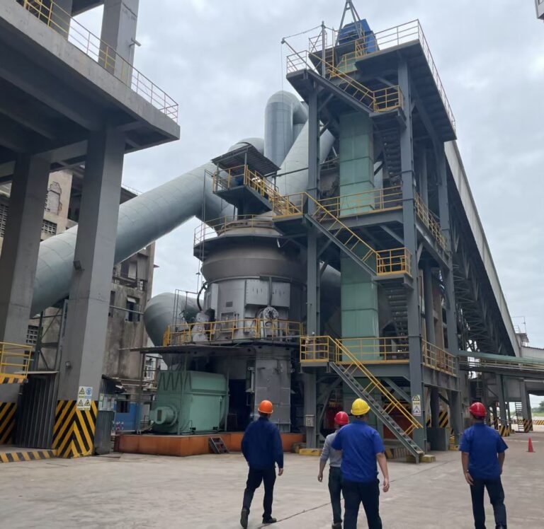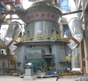


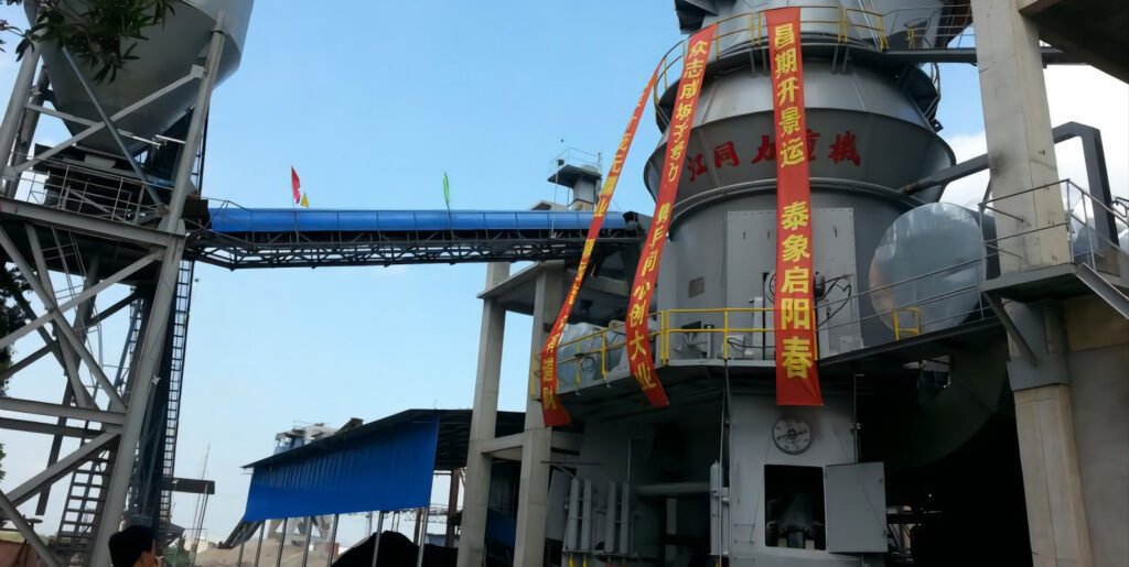
The 4000t/d new dry process cement production line was designed by Tongli Heavy Machinery and officially put into production in October 2003. The raw material vertical roller mill of this line is the ZJTL46.4 designed and manufactured by Zhejiang Tongli Heavy Machinery. After nearly two years of production practice and exploration, the main control parameters of the system have been optimized and adjusted, so that it can achieve stable production. This article introduces the characteristics, working principle and operation of the vertical roller mill close circuit grinding system.
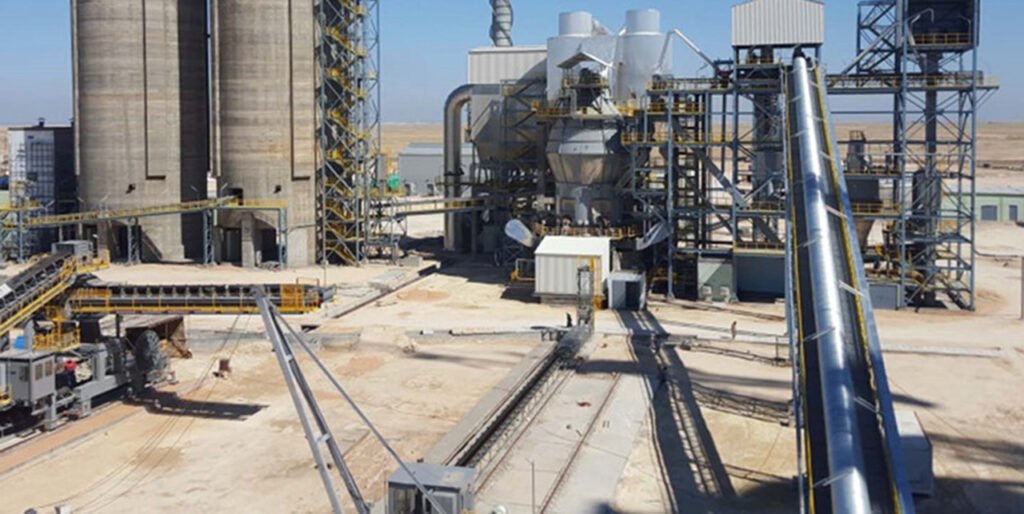
What is The Process Flow of Dry Process Cement Vertical Roller Mill Grinding System?
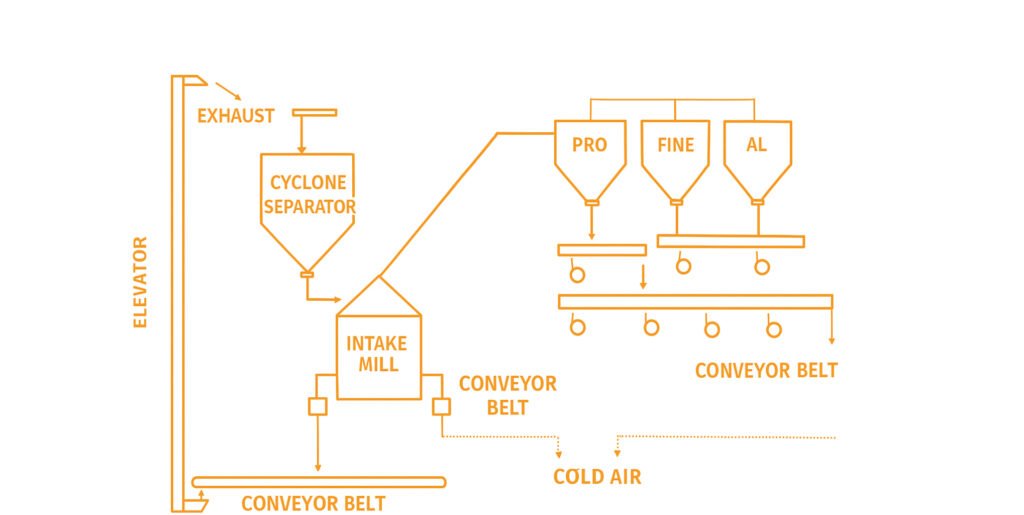
1. Material Feeding via Elevator
Raw materials are being transported by vertical bucket elevator to an overhead cyclone separator.
- Component: Vertical bucket elevator.
- Function: Transports raw materials (limestone, slag, fly ash, etc.) from ground level to the cyclone separator.
- Flow rate estimate: 100–250 t/h depending on the elevator capacity.
2. Cyclone Separator (Pre-separation)
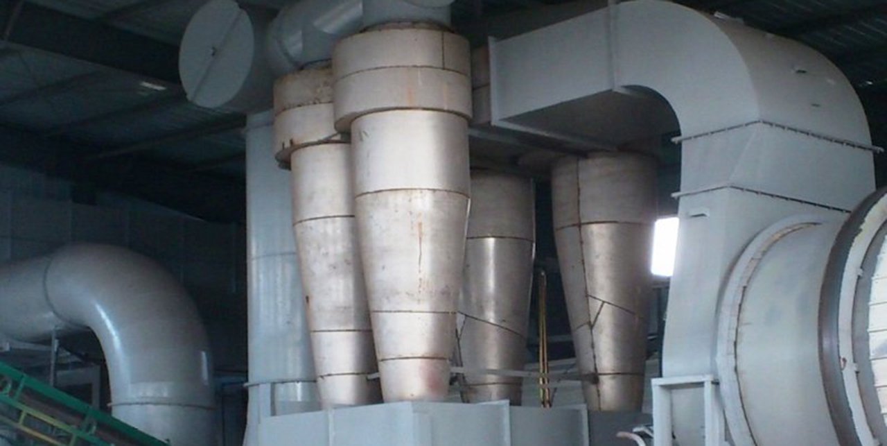
The cyclone separator using centrifugal force to remove coarse particles and dust. Finer materials are separated by the airflow, and the coarse components drop to the bottom of the cyclone and are directed toward the vertical mill for grinding. At this point, exhaust gases generated during separation are vented out through a duct to ensure pressure stability and minimize dust emissions.
- Component: Cyclone dust separator.
- Function: Performs preliminary separation of fine dust from the feed material using centrifugal force.
- Working principle: Heavier particles are collected at the bottom, fine particles are carried with air to the next stage.
- Dust separation efficiency: Typically 85–90%.
- Outlet: Connected to an exhaust pipe and sends material to the vertical mill.
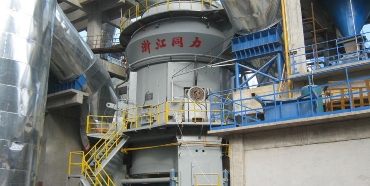
3. Vertical Roler Mill Grinding
The separated raw material enters the vertical roller mill, which serves as the central grinding unit. This mill uses hydraulic pressure and the rotation of grinding rollers against a grinding table to reduce the feed material, typically under 50 mm in size into fine powder. The vertical mill includes an integrated dynamic classifier that continuously adjusts the fineness of the product. The target product fineness is typically below 80 microns, with a residue on the 45 µm sieve below 10%.
- Component: Vertical roller mill (with integrated classifier).
- Function: Grinds the raw materials into fine powder through compression and shearing forces between the rollers and the grinding table.
- Input feed size: < 50 mm
- Output fineness: Typically < 80 μm (residue on 45μm sieve < 10%)
- Power consumption: 18–30 kWh/t
- Features: Includes dynamic air classification system to control fineness.
4. Powder classification
Once grinding is complete, the powder is pneumatically conveyed to a multi-stage classification system composed of several silo-like bins. These bins are labeled according to function: coarse material, air-separated fine powder, general dust, and ultrafine particles or baghouse returns. Each bin is equipped with rotary discharge valves and sits above individual conveyor belts. This setup allows for efficient segregation and controlled discharge of various material grades. Materials are then transferred via conveyor belts to downstream processes such as packaging, blending, or storage. These belts are supported by rollers and often equipped with weight sensors to monitor flow rates in real time.
Component: Multi-bin classifier with air separation
- Coarse powder bin
- Air-separated fine powder bin
- Dust bin
- Ultra-fine or collected dust bin
Function:
- Sorts the ground material based on particle size using airflow.
- Returns oversized particles to the vertical mill.
- Directs classified product to corresponding bins.
5. Product Discharge via Belt Conveyors
Materials are then transferred via conveyor belts to downstream processes such as packaging, blending, or storage. These belts are supported by rollers and often equipped with weight sensors to monitor flow rates in real time
- Component: Multiple belt conveyors.
- Function: Transfer of classified material to downstream processing or storage silos.
- Capacity: Varies; typically designed for 100–300 t/h.
6. Air Handling System
Air and dust handling is also considered in the system. A dedicated fan and air return pipeline facilitate the circulation of process air, drawing it through the classifier system and returning it to the mill or releasing it through bag filters or ESPs (electrostatic precipitators). This design minimizes dust emissions to less than 30 mg/Nm³, in compliance with standard environmental regulations (e.g., GB 16297-1996 in China). Moreover, the circulating air reduces the need for fresh air intake, improving energy efficiency.
- Component: Induced draft fan, exhaust fan, and air return pipeline.
- Function:
- Maintains negative pressure in the system.
- Recycles filtered air or exhausts excess to maintain environmental compliance.
- Connected to dust collectors for clean air discharge.
- Key parameters:
- Airflow rate: ~30,000–80,000 m³/h
- Dust emissions: < 30 mg/Nm³ (complying with GB standards)
What are the Features of Tongli ZJTL Model 46.4 Vertical roller mill
1. Strong adaptability to materials.
In our company's use, the adaptability of this mill to materials is specifically manifested in the following two aspects. First, the mill requires the particle size of the inlet mill to be ≤70mm. In actual production, due to the brittleness of our ore, the limestone entering the mill after crushing is too fine and has more powdery particles, but the material layer of the mill is stable. In addition, the particle size distribution of the sandstone purchased by our factory is also very uneven, and some particles are large, but the mill runs relatively smoothly. Second, our company's limestone yard is an open-air yard, and the moisture content of the auxiliary raw materials (clay and sulfuric acid slag) is high, sometimes as high as 25%, but the moisture content of the raw materials leaving the vertical mill can reach 100%. Sometimes the material humidity is low. In order to form a stable material layer for the vertical mill, it is usually necessary to spray 4-5t/h or even more water into the mill to still ensure the moisture content of the raw materials leaving the mill. When there is insufficient hot air and the outlet temperature of the mill is low, stop spraying water into the mill to ensure the outlet temperature of the mill; at this time, the mill can still form a stable material layer and achieve stable operation.
2. Internal and external material circulation system.
The system has two internal and external material cycles. After the raw material falls to the center of the grinding disc through the discharge chute, as the grinding disc rotates, the material enters between the grinding disc and the grinding roller for grinding due to the centrifugal force. The material that has been crushed and ground by the high-speed rotation of the grinding disc is thrown to the coarse slag discharge port (i.e., the wind ring) around the grinding disc and is blown up by the high-speed rising airflow and brought into the mill. As the wind speed in the mill decreases, the coarser particles fall onto the grinding disc for secondary grinding, and the remaining powder is separated by the air flow through the powder selector. The qualified fine material is discharged from the air outlet and collected by the cyclone dust collector as the raw material product; the coarser powder also falls onto the grinding disc for re-grinding. This is the internal cycle. On the other hand, the coarse slag falling from the wind ring is of larger particle size and is not lifted by the hot air. It enters the slag discharge belt through the material discharge chute, and then is lifted by the circulating bucket and enters the buffer bin to enter the mill again with the material for secondary grinding. This is the external circulation system.
3. High output and low power consumption.
The wind speed at the wind ring of ZJTL 46.4 vertical mill is only 30-40m/s (while the wind speed at this wind ring of some types of vertical mills is as high as 90m/s), which reduces the ventilation volume and wind pressure of the system and reduces the energy consumption of the circulating fan (the power of this vertical mill is 2600kW, and it is equipped with Y6-2×30-14No.33F circulating fan. The rated air volume of the fan is 660000m3/h, the wind pressure is 12.35 kPa, and the power is 3200kW); as the upward material carrying capacity of the mill decreases, more coarse slag is discharged from the wind ring (accounting for about 20-30% of the feed amount), and then the coarse slag is lifted back to the mill for grinding by the hoist. That is, mechanical lifting is used instead of pneumatic lifting, which achieves the purpose of saving fan power. In addition, the flow speed of the material is accelerated, and the mill always maintains an efficient grinding state, so that the material in the mill does not have over-grinding phenomenon, and the mill output has been greatly improved, which plays a decisive role in reducing the power consumption of the mill. The comprehensive electricity consumption of our company in producing raw materials in the first half of 2005 is shown in Table 1.
Table 1: Comprehensive Power Consumption of Raw Meal in 2005 (kWh/t)
| Month | Power Consumption (kWh/t) |
| January | 21.75 |
| February | 21.75 |
| March | 21.35 |
| April | 20.33 |
| May | 21 |
| June | 22.24 |
How to ensure the stable operation of the vertical mill?
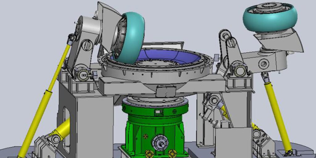
1. Grinding pressure
- Grinding pressure is generated by the hydraulic system. The hydraulic system has a hydraulic station and four hydraulic cylinders. Each hydraulic cylinder is connected to an accumulator. The accumulator is filled with nitrogen. Its function is to buffer the mechanical load during the grinding process. In order to protect the roller sleeve and liner during the operation of the mill, there is a certain distance between the grinding roller and the grinding disc. Our company currently sets it at about 10mm. The four grinding rollers are connected to their respective hydraulic cylinders through rotating arms and pull rods. When the pump station is working, grinding pressure will be generated. During the pressurization process, the thickness of the material layer and the change in the grinding pressure have a great impact on the performance of the mill, which is directly related to the output. The higher the pressure, the stronger the grinding effect and the higher the output, and vice versa. However, the grinding pressure cannot be too large, otherwise it will increase useless work; and the grinding parts will wear rapidly.
- The grinding pressure is not only related to the pressure of the hydraulic cylinder, but also to the size of the nitrogen bag pressure. If the nitrogen bag pressure is too large or too small, it will not play a role in buffering and reducing vibration. The nitrogen bag pressure is generally controlled within the range of 60% ± 10% of the grinding pressure. At present, the grinding pressure of our vertical mill is controlled between 4 and 6 MPa, and the operation is relatively stable when the nitrogen bag pressure is set to 3.5 MPa. If the vibration becomes larger during operation, timely adjustments should be made (such as reducing the feed amount and reducing the grinding pressure, etc.) to avoid excessive vibration; after the grinding condition improves, the output can be gradually increased. If the adjustment parameters are ineffective and the vibration is too large, the roller should be raised in time and the on-site inspection should be notified.
2. Vibration value
Vibration is a common phenomenon in the operation of vertical mills. Reasonable vibration values are allowed, but if the vibration is too large, it will cause mechanical damage to the grinding disc, grinding roller and liner. Therefore, during operation, the vibration value should be strictly controlled within the allowable range to ensure stable operation. The reasonable vibration value allowed by Ube UM46.4 vertical mill is generally 10 to 30 μm/s. There are many reasons for mill vibration, which can be summarized as follows: fluctuations in air volume and air temperature; excessive grinding pressure; foreign matter in the mill (such as iron blocks); too thick or too thin material layer; excessive or too small nitrogen bag pressure; large fluctuations in feed volume; abnormal water spray volume; low air volume; excessive feed volume, etc. The technical measures that can be taken to control mill vibration in production include: appropriate reduction of feed volume to reduce grinding pressure; at the same time, adjust the opening of each baffle according to the main machine current and the gas temperature at the mill outlet; if necessary, even the roller can be raised to avoid excessive vibration.
3. Material layer thickness
Whether the material layer is stable is the premise for the stable operation of the mill. When the height of the baffle ring remains unchanged, the thickness of the material layer is related to the water spray volume, air volume, and air temperature in the mill. The judgment of whether the material layer is stable or not mainly depends on the main machine current of the mill, the amount of slag material discharged (the mill of our company does not have a material layer display), and the vibration value of the mill, etc. It can also be visually inspected on site. The optimal material layer thickness depends on the raw material particle size, grindability, particle grading and water content, which requires the operator to make accurate judgments and reasonable adjustments based on the mill power, vibration value, powder selector power and mill output.
The material layer thickness is the main reason affecting the vibration of the vertical mill. Therefore, if the material layer is abnormal during operation, the material layer should be stabilized by adjusting the water spray volume, grinding pressure, circulating air volume and powder selector speed in time. If the operation requirements of the optimal material layer cannot be met, the height of the retaining ring should be adjusted.
In the early stage of commissioning, our factory could only use the hot air furnace to dry the material because the kiln was not ignited, resulting in insufficient air volume in the vertical mill and unable to form a material layer, so that the grinding roller could not be lowered. For this reason, the height of the retaining ring was increased from 128mm to 137mm, so that the mill could operate continuously and stably for 2h, and the output could reach 160-180t/h. Later, when the kiln was ignited and could provide a large amount of hot air, we adjusted the height of the retaining ring several times to increase the output (see Table 2 for specific adjustment values). If the material is soft or the product is required to be coarse, it is beneficial to have a slightly higher retaining ring. In addition, a low retaining ring helps to increase production, but as the roller sleeve and liner wear, the gap between the grinding roller and the grinding disc will become larger and larger, and the roller cannot be lowered, and there may also be large vibrations. At this time, the height of the retaining ring should be appropriately increased to stabilize the operation of the vertical mill.
Table 2: Adjustment Statistics of Material Retaining Ring Height
| Date (Year-Month-Day) | Change (mm) | Height After Adjustment (mm) | Purpose |
| Initial | 0 | 128 | — |
| 2003-10-22 | +9 | 137 | Ensure material layer |
| 2003-10-26 | -9 | 128 | Increase production |
| 2004-03-05 | -10 | 118 | Increase production |
| 2004-10-09 | -12 | 106 | Increase production |
| 2004-12-20 | +6 | 112 | Protect roller sleeve |
| 2005-07-20 | +9 | 121 | Ensure roller descent |
4. Pressure difference
Pressure difference is also one of the most important control parameters in vertical mill operation. The size of pressure difference can reflect the amount of material in the mill. The operator can understand the situation in the mill by observing the pressure difference. A large pressure difference indicates that there is a lot of material circulating in the mill. The main reasons for this are: excessive feed volume, insufficient grinding pressure, excessive speed of the classifier and insufficient air flow. If the pressure difference is found to be too high during operation, it should be judged in time according to the comprehensive parameters and appropriate adjustments should be made to improve the working conditions in the mill. A small pressure difference indicates that there is less material in the mill. If the product quality is qualified, it is generally caused by insufficient feed. The feed volume can be appropriately increased. If the product fineness is unqualified, it may be caused by low speed of the classifier or excessive air flow. The air flow should be appropriately reduced or the speed of the classifier should be increased to improve it.
5. External circulation volume.
In addition to being related to the design, the external circulation volume of the mill is also related to the wind speed at the wind ring and the height of the material retaining ring. The lower the wind speed, the greater the external circulation volume. External circulation can reduce the exhaust load, avoid over-grinding, and reduce power consumption. However, if the external circulation volume is too large, it will lead to an increase in the main engine power, severe wear of the scraper plate, and the inability to increase the output. In severe cases, it may even cause the mill belt or elevator to trip. At present, our factory generally controls the external circulation volume at 20% to 30%, and the operation is relatively stable.
6. The temperature of the flue gas and water spray amount
- The temperature of the gas out of the mill can be controlled. If the outlet temperature is too high, it will cause the powder selector cage to deform or the bearing to be damaged; if the outlet temperature is too low, it will cause the raw material moisture out of the mill to be too high and the material layer in the mill to be too thick. At present, the outlet temperature of our factory's vertical mill is generally controlled between 75 and 90°C. In the later stage of wear of the roller sleeve and liner of the mill, in order to ensure that the mill forms a stable material layer, the outlet temperature of the mill should be appropriately reduced. In the later stage of wear of the mill liner, the outlet temperature of our factory is controlled at 65°C, and the mill operation is relatively balanced. The outlet temperature of the mill is mainly controlled by the inlet gas temperature, air volume and the amount of water sprayed in the mill.
- The role of the water spray is to stabilize the material layer. Too much water spray will form material cakes, causing the situation in the mill to deteriorate. The amount of water spray can be adjusted according to the actual situation. However, if the outlet gas temperature is low, as long as a good material layer can be formed, the water spray can be reduced or even stopped to increase the outlet temperature of the mill. The actual operating parameters of the vertical mill are shown in Table 3.
Table 3: Actual Operational Control Parameters of the Mill:
| Parameter | Value |
| Main Motor Current (A) | 250 |
| Circulating Fan Current (A) | 355 |
| Feed Rate (t/h) | 350 |
| Inlet Air Temperature (°C) | 250 |
| Outlet Air Temperature (°C) | 80 |
| Water Spray Amount (m³/h) | 3 |
| Pressure Differential (Pa) | 5900 |
Typical problems and solutions encountered in vertical mill production operation
1. High-pressure pump outlet low pressure alarm
- (1)During the mill commissioning, the reducer high-pressure pump outlet low pressure alarm frequently occurred, causing the mill to stop, and the reason was unknown. Later, Japanese experts changed the alarm value to 1.5MPa (the original setting value was 2.45MPa), so that the mill could operate stably. They analyzed the pressure of 12 large tiles one by one to eliminate the cause. It was found that the mill could not be pressurized to the normal value due to the thin material layer. At this time, the high-pressure pump outlet pressure was low and the mill was stopped.
- (2) After the mill was running normally, the reducer high-pressure pump outlet low pressure alarm also occurred. According to the data of the central control, everything was normal, but the belt was actually slipping on the spot. There was no material fed into the mill, that is, there was no material layer in the mill. Therefore, when the roller was lowered, there was no material layer and the mill could not be pressurized. The high-pressure pump outlet pressure was low and the mill was stopped.
- (3) As the roller sleeve and liner wear, in order to ensure the roller is lowered, the electrical limit and mechanical limit (i.e., positioning stop iron) are usually adjusted accordingly. If the adjustment of the mechanical limit does not keep up with the adjustment of the electrical limit, when the material layer in the mill is not very good, the roller will hit the mechanical limit before it hits the electrical limit when the roller is lowered. As a result, the roller pressure of the mill is reduced, and the outlet pressure of the high-pressure pump is low, causing the mill to stop.
2. The roller does not drop
- (1) In the early stage of production commissioning, the kiln was not ignited and the mill used a hot air furnace to provide hot air. After feeding, the roller could not be lowered into place. On-site observation showed that the roller always hit the lower limit switch and raised the roller, and the slag discharge was abnormally high. We believe that the air volume of the hot air furnace is too small, so that the material layer is not formed in the mill. Therefore, the height of the retaining ring is increased to force the material layer to form in the mill. After treatment, the roller can be smoothly lowered into place.
- (2) After the production gradually returned to normal, the roller could not be lowered. The main reason was that the operator did not grasp the time of lowering the roller and the roller could not be lowered to the normal position. After multiple roller lowering, the material was kept circulating in the mill, which led to the deterioration of the grinding condition and the inability to form a material layer. In this case, the circulating material in the mill should be discharged and production can be restored to normal.
- (3) After the roller sleeve and liner are worn, the gap between the roller and the grinding disc will become larger and larger. In this way, during the process of lowering the roller, the roller hits the lower limit and the roller is raised before it touches the material layer, resulting in the inability to lower the roller normally. Usually, as the roller sleeve and liner wear, the electrical limit and mechanical limit must be adjusted in time to ensure the stable operation of the mill.
Conclusion:
Among the grinding equipment for cement production, vertical mill has many technical advantages such as high output, low power consumption and strong adaptability to materials. However, the operation and control of vertical mill is much more difficult and complicated than that of tube mill. In the design of vertical mill, our company has accumulated certain operation and maintenance experience through the optimization control of the above operating parameters and the exploration and summary of production problems encountered, thus ensuring that the ZJTL46.4 vertical mill can operate continuously and stably, laying the foundation for the normal operation of the kiln system.