


Cement Grinding Plant Introduction:
A cement grinding plant is a facility that grinds cement clinker, gypsum, and supplementary materials into finished cement. Cement grinding plants are mainly divided into two types: raw material grinding plants and cement clinker grinding plants. Raw material grinding unit focuses on grinding limestone, clay, and other raw materials into fine raw meal before the calcination process, while cement clinker grinding plant is the final stage of cement production where clinker is mixed with gypsum and supplementary materials such as slag, fly ash, or limestone to produce finished cement. Modern cement grinding plants commonly use vertical roller mills (VRM), ball mills, and roller press (HPGR) grinding systems. Advanced pre-grinding technology can reduce feed particle size and create internal cracks in the material, significantly improving grinding efficiency. Both open-circuit and closed-circuit grinding systems are widely used depending on capacity and product fineness requirements. Cement clinker grinding plant can also process industrial by-products and waste materials such as blast furnace slag(GGBFS), steel slag, fly ash, and coal gangue, making them an energy-saving solution for modern cement manufacturing. In this article we will introduce the cement grinding plant equipment, process flow and proper silo storage of cement powder and stockpile storage of clinker.
Equipment In Cement Grinding Plant
The main grinding equipment used in a cement grinding plant includes vertical roller mills (VRM), ball mills, roller press (HPGR) systems, and Horomills for cement clinker and raw material grinding.
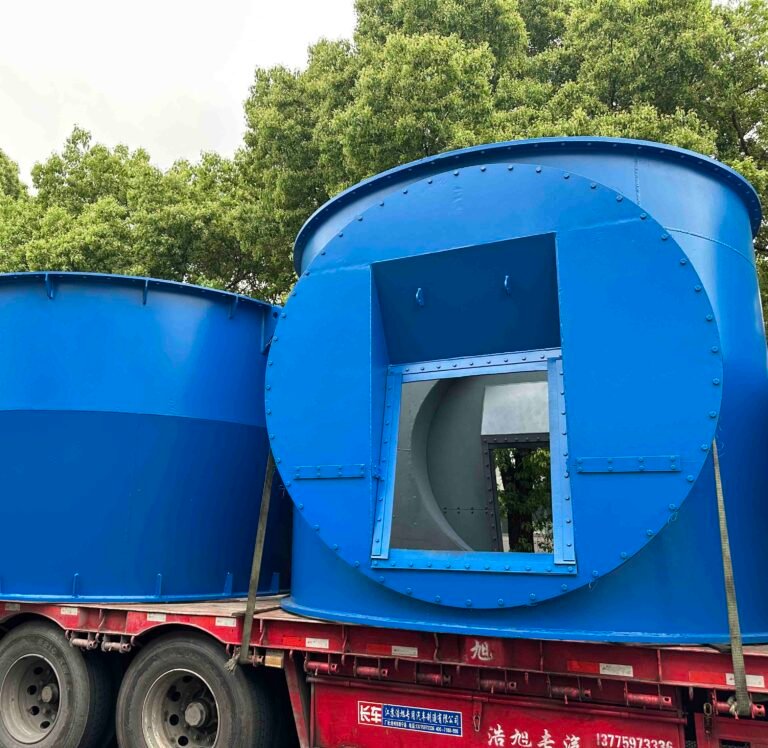
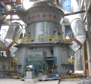
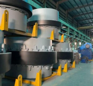
Cement Grinding Plant Vertical Roller Mill
Cement vertical roller mill(VRM) in a cement grinding plant is a grinding machine that uses Voestalpine certified fluxcore welding wire hard facing grinding rollers and a rotating grinding table to grind cement clinker, slag, limestone, and other materials into fine powder. VRMs are widely used for cement clinker grinding and raw material grinding due to their integrated grinding, drying, and classification functions. Compare to Ball mill and HPGR it has the following adventages:
Adventages using Vertical roller mill in cement grinding unit
- Lower electricity consumption than traditional ball mills
- Can integrate grinding, drying, and powder classification in one machine
- Able to dry high-moisture materials using hot gas inside the mill
- Can be installed outdoors with less need for a large workshop or rain cover
- Smaller installation footprint compared with ball mill systems
- Lower steel ball and grinding media consumption
- Lower noise and dust generation
- Higher production capacity for large-scale cement plants
- Suitable for grinding clinker, slag, coal, and raw materials in one system
- Easier process automation and centralized control
Why Choose Vertical roller mill for cement grinding?
Vertical roller mills (VRMs) were initially developed for coal grinding and raw material grinding applications. Their use in cement grinding, which requires much finer particle size control and stricter product quality standards, was not widely adopted until the late 1990s. The delayed adoption of VRM technology in cement finish grinding was mainly due to concerns from cement producers regarding whether the final cement quality could meet market requirements, particularly in terms of water demand, compressive strength, and setting time. However, over the past two decades, these concerns have proven to be largely unfounded. Industrial operation has demonstrated that cement produced by VRMs can achieve quality comparable to, and in some cases superior to, cement produced by conventional ball mill systems. As a result, most leading global cement manufacturers now widely utilize vertical roller mills for cement grinding applications. One of the most significant advantages of VRMs is their superior energy efficiency. Depending on the optimization level of the grinding circuit, the specific power consumption of a conventional ball mill system is typically 1.5 to 2 times higher than that of a VRM performing the same grinding duty.
Temperature Control Advantages of Vertical Roller Mills in Cement Grinding
In conventional ball mill systems, most of the electrical energy used during grinding is converted into heat. Excessive cement temperature during the grinding process can negatively affect cement quality and may lead to setting time abnormalities. To prevent overheating, part of the generated heat must be dissipated by cooling the mill and the material inside it. This cooling process is typically achieved either by circulating ventilation air through the mill or by injecting water into the grinding chamber to absorb heat through evaporation. When water injection systems are used, careful control is required to ensure that all injected moisture fully evaporates and that water vapor does not condense inside the mill compartments. For this reason, automatic control systems are commonly installed to regulate the water spray rate and maintain stable operating temperatures. Compared with conventional ball mills, vertical roller mills (VRMs) generate significantly less heat during cement grinding. As a result, the risk of cement quality issues caused by excessive grinding temperatures is greatly reduced. Although VRMs may still use water injection on the grinding table to stabilize operation and minimize vibration, their overall thermal management is more efficient and easier to control.
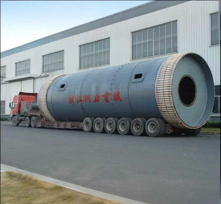
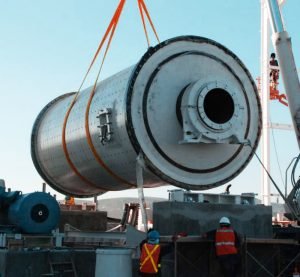
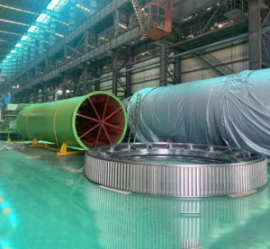
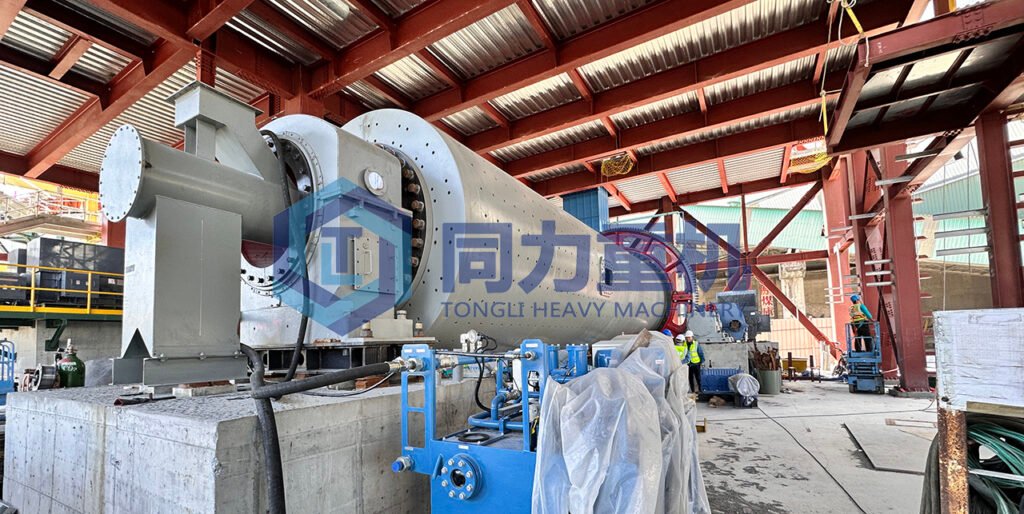
Cement Grinding Plant Ball Mill
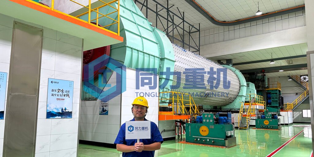
A cement grinding ball mill is designed as a horizontal rotating cylinder consisting of two or three grinding compartments. Inside the mill, steel grinding media of different sizes are used to grind clinker and raw material limestone into fine cement through a combination of impact force and attrition. Cement clinker, gypsum, and supplementary materials are fed into the mill through one hollow trunnion, while the finished ground material exits through the discharge trunnion at the opposite end. Traditionally, ball mill systems were used for all three grinding stages(raw material grinding, clinker grinding, additives like slag gypsum grinding and Fuel coal grinding) in cement production, but many plants have gradually shifted toward more energy-efficient vertical roller mill (VRM) technology. However, ball mills still offer several advantages.
Cement Ball Mill Closed-Circuit Cement Grinding Plant Video
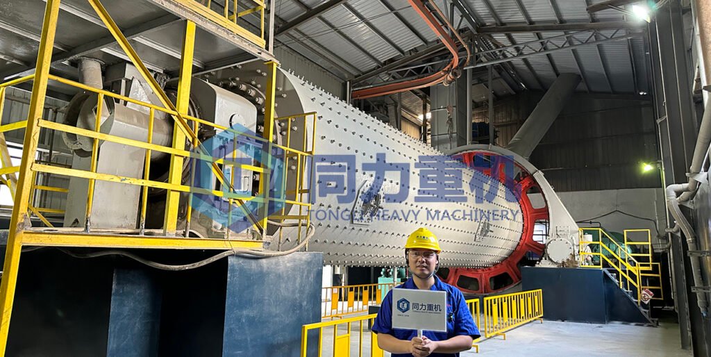
Typical Dimensions and Grinding Media Configuration of Cement Ball Mills
For a conventional two- or three-chamber ball mill system, a common mill size is approximately 13.5 meters in length and 2.5 meters in diameter, operating at a rotational speed of around 20 rpm. These mills generally contain about 90 tons of steel grinding media. Larger grinding balls, typically ranging from 90 mm to 60 mm, are installed in the first chamber for coarse grinding, while the second chamber uses smaller media between 50 mm and 15 mm. In the final chamber, even finer grinding media below 15 mm are used to achieve the target cement fineness.
What is Ball Mill Diaphragm?
A ball mill diaphragm is a perforated partition plate that separates grinding chambers while allowing properly ground material to pass through and retaining the grinding media in each compartment. Each grinding compartment is separated by a perforated diaphragm. These diaphragms allow properly ground material to pass to the next chamber while retaining the grinding media within their designated sections. Ball mills of this configuration are commonly powered by motors around 1200 horsepower, although industrial cement mills can range from 500 hp to 6000 hp depending on plant capacity. Cement production output can vary from approximately 10 tons per hour up to 140 tons per hour. Some combined grinding ball mills are designed with only two compartments. In these systems, the first chamber uses large grinding balls similar to those found in a conventional three-chamber mill for coarse grinding, while the second and larger compartment is fitted with a classification liner that maintains a gradual distribution of grinding media sizes along the chamber length.
Why Are Clinker Grinding Ball Mills Larger Than Raw Material Ball Mills?
Cement clinker is harder and more difficult to grind than raw materials, and it also requires a much finer final product fineness. For this reason, clinker grinding ball mills are generally designed larger and operate with longer grinding retention time compared with raw material grinding mills.
Why Is Ball Mill Rotational Speed Important?
The rotational speed of a ball mill is carefully selected during the design stage to achieve the most efficient grinding performance. As the mill rotates, the grinding media are lifted along the inner shell of the mill to approximately the “10 o’clock” position before falling onto the material to generate impact and grinding action. If the mill rotates too fast, centrifugal force will cause the grinding media to cling to the mill shell without falling, greatly reducing grinding efficiency. On the other hand, if the rotational speed is too low, the grinding balls cannot be lifted high enough to create sufficient impact force for effective crushing. In general, larger diameter ball mills operate at lower rotational speeds. Depending on the mill size and design, typical operating speeds are usually between 15 and 20 revolutions per minute (rpm).
Ball Mill Grinding Media Wear, Recharging, and Maintenance Procedures
During continuous mill operation, the steel grinding media gradually wear down and require regular replenishment. Larger grinding balls are periodically added to each grinding chamber to maintain grinding efficiency. After longer operating periods, the entire grinding media charge may be removed, sorted, and reclassified, while excessively worn or deformed media are discarded. These maintenance shutdowns are also used to inspect and repair internal mill components such as liners, diaphragms, and compartment partitions.
Cement Grinding Plant High Pressure Grinding Roller(HPRG)
HPGR (High Pressure Grinding Roll), also called a roller press, is a cement grinding machine that uses two counter-rotating rollers to compress and crush clinker, slag, limestone, and other materials under high pressure. Unlike traditional ball mills, HPGR grinding mainly relies on inter-particle crushing inside the material bed rather than impact grinding. During the grinding process, the high pressure creates micro-cracks inside the clinker particles, which improves the efficiency of the downstream grinding system and reduces power consumption. In cement grinding plants, HPGR systems are commonly used together with ball mills as a pre-grinding system or combined grinding system to increase production capacity and reduce operating costs. Compared with traditional ball mill systems, HPGR grinding plants typically consume less electricity, require less grinding media, and provide higher grinding efficiency and plant output.
Horomill in Cement Grinding Unit
Horomill, also called a horizontal roller mill, is a cement grinding machine that uses a rotating grinding shell and a grinding roller to grind clinker, slag, limestone, and other materials into fine cement powder. Unlike conventional ball mills, the Horomill uses bed compression grinding with lower grinding pressure and reduced circulating loads. In a cement grinding plant, Horomill systems are commonly used for cement finish grinding and slag grinding applications. The grinding process generates less heat and lower vibration compared with traditional ball mills, which helps improve grinding stability and cement quality control. Compared with conventional ball mill systems, Horomills typically offer lower electricity consumption, reduced grinding media wear, lower operating noise, and a more compact installation layout while maintaining high grinding efficiency.
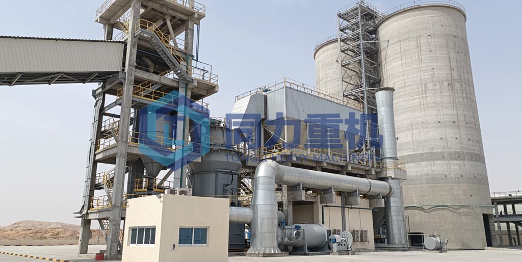
Process Flow of cement grinding Plant
The process flow of a cement grinding plant mainly includes raw material handling, weighing and mixing, grinding, separating, finished cement storage, conveying, and packing. Here we are using a Slag grinding plant's process flow diagram as an example:
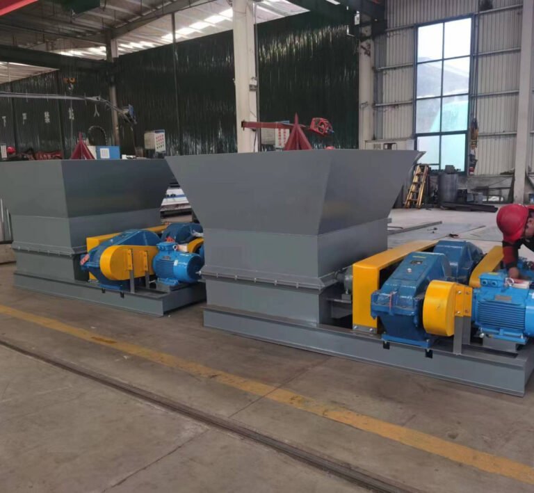
Raw Material Handling
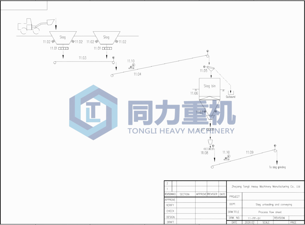
Slag is delivered to the receiving area by loader and discharged into the slag receiving hoppers. According to the process flow diagram, the slag is extracted from the receiving hoppers through feeder systems (11.01) equipped with level monitoring devices (11.02). The material is then transported by belt conveyors (11.03 and 11.04) toward the slag storage bin. Before entering the slag bin, the material passes through a transfer point and feeding chute system (11.05). The slag bin is equipped with level indicators (11.06) to monitor storage capacity and ensure stable material flow. At the bottom of the slag bin, the material is discharged through extraction equipment and feeding devices (11.07), then transferred onto the downstream belt conveyor system (11.08 and 11.09) for delivery to the slag grinding section. Magnetic iron removers (11.10) are installed along the conveyor system to remove tramp iron and protect the grinding equipment from metal contamination and mechanical damage.
Cement Plant Grinding Process
In the grinding process, ball mills, vertical roller mills (VRM), roller press (HPGR), or Horomill systems are used to grind clinker and mixed materials into fine cement powder. The separator classifies the ground material, where qualified fine powder is collected as finished cement while coarse particles are returned to the grinding mill for further grinding in a closed-circuit system. After separation, the finished cement is transported by air slide conveyors, bucket elevators, and pneumatic conveying systems into cement silos for storage. So here we are giving an exmaple of a cement grinding using Vertical roller mill.
Vertical roller mill cement grinding plant slag grinding process:
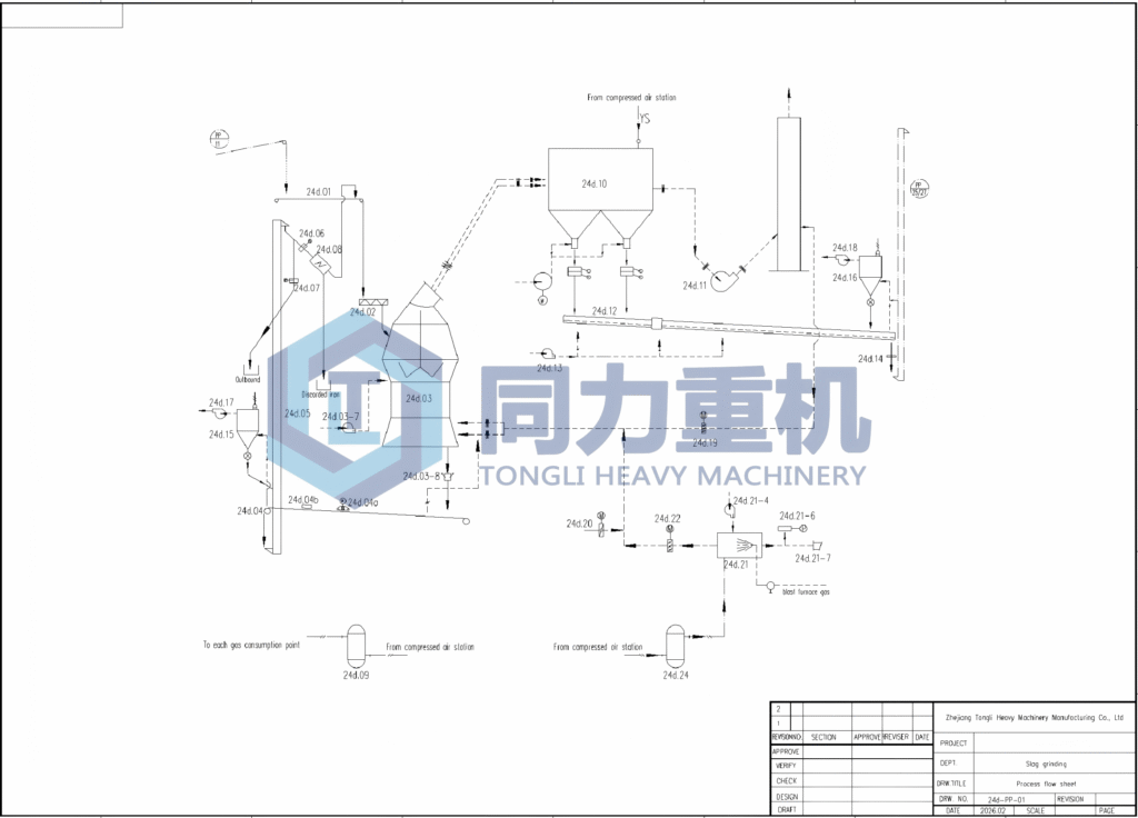
- The slag material discharged from the raw material handling section is transported by the belt conveyor system into the bucket elevator (24d.01), which lifts the material to the feeding system of the vertical roller mill grinding circuit. The slag then passes through the feeding device and air lock system (24d.02) before entering the vertical roller mill (24d.03).
- Inside the VRM, the material is ground between the rotating grinding table and grinding rollers under hydraulic pressure. During the grinding process, hot gas generated by the hot gas furnace system (24d.21) is introduced into the mill to simultaneously dry and transport the material. The gas flow carries the fine particles upward into the internal separator section of the mill, while coarse particles fall back onto the grinding table for further grinding in the closed-circuit system.
- The qualified fine powder and gas mixture exits the mill and enters the dust collection and separation system. Fine particles are collected by the bag filter / dust collector (24d.10), while the cleaned gas is extracted by the main exhaust fan (24d.11) and discharged through the stack system. Auxiliary dust collection equipment (24d.16 and 24d.17) is also installed at transfer points to control dust emissions throughout the process.
- The collected finished slag powder is discharged through the air slide conveyor (24d.12) and transported by the bucket elevator system (24d.14) to the finished product storage or downstream conveying system. Compressed air systems and air tanks (24d.24) are used for pulse cleaning and pneumatic operation of the grinding and dust collection equipment, ensuring stable continuous operation of the slag grinding plant.
Cement Grinding Staion Packaging Process:
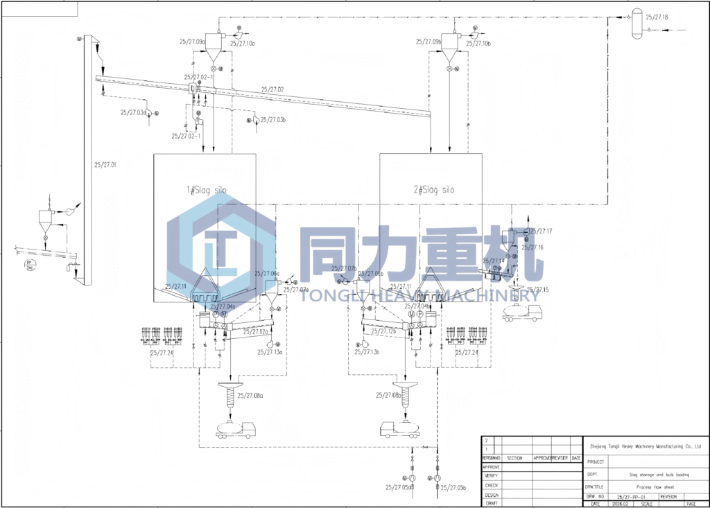
1. Silo Discharge and Flow Control
The cement (or slag) starts in the storage silos, labeled 1# Slag Silo and 2# Slag Silo. Each silo is equipped with discharge gates and conveying mechanisms that control the flow of material into the packing system. Flow from the silos is regulated by valves or flow sensors, ensuring that material is discharged consistently without clogging.
- Item 25/27.02-1 & 25/27.02 – Silo discharge gates and conveyors.
- Item 25/27.03a & 25/27.03b – Flow control valves or sensors for regulating discharge rate.
2. Weighing and Batching
After leaving the silos, the cement moves into weighing or batching hoppers. These hoppers measure the exact amount of material to be loaded into trucks. This step is critical to ensure the correct batch weight and maintain operational efficiency.
- Item 25/27.04a & 25/27.04b – Weighing hoppers for 1# and 2# silos.
- Item 25/27.11 – Vibrators and ariation device to prevent bridging or clogging in the hopper.
3. Conveying to Loading Points
Once weighed, the cement is transported via screw conveyors down to the truck loading stations. The conveyors maintain steady material flow and minimize dust emissions during transport.
- Item 25/27.08a & 25/27.08b – Screw conveyors moving material from hoppers to truck loading.
- Item 25/27.12a & 25/27.12b – Gates at conveyor ends for controlled flow into trucks.
4. Truck Loading
At the bottom of the system, trucks are positioned to receive the cement. Truck weighing systems ensure that the correct amount of material is loaded into each vehicle. Operators can adjust the flow as needed to prevent overfilling.
- Item 25/27.13a & 25/27.13b – Truck scales or weighing systems.
- Conveyors discharge directly into trucks.
5. Dust Collection and Airflow
To maintain a clean and safe working environment, the packing system integrates dust collectors and airflow control. Dust generated during silo discharge, conveying, or truck loading is captured to prevent environmental contamination.
- Item 25/27.16 & 25/27.17 – Dust collectors or filters connected to conveyors and silos.
- Ducting ensures proper airflow and pneumatic transport where needed.
Open-circuit cement grinding plant VS closed-circuit cement grinding plant
Cement plant grinding can be performed using either open-circuit or closed-circuit systems. In an open-circuit grinding system, all material passes through the mill only once and is ground directly to the required cement fineness in a single process step. In a closed-circuit grinding system, the material discharged from the mill is separated by a classifier or separator. Fine particles that meet the required fineness are sent to the cement silos, while coarse particles are returned to the mill for further grinding. This circulating load system improves grinding efficiency and allows better control of cement particle size distribution. Besides open circuit and closed-circuit there's another type of cement grinding plant which has become the main stream which is called combined grinding system.
What is open-circuit cement grinding plant?
Open-circuit cement grinding plants, also known as open-flow grinding systems, are the simplest type of cement grinding process. In this system, clinker, gypsum, and other additives pass through the grinding mill only once before becoming finished cement. After grinding, the material is discharged directly from the mill outlet and transported to the cement silo without any classification or material recirculation process. Since the system does not include separators or classifiers, the overall process flow is relatively short and simple, requiring fewer auxiliary machines and lower initial investment. Installation, operation, and maintenance are also comparatively convenient, making open-circuit systems suitable for small-scale cement grinding stations or low-capacity production lines.
Why open-circuit cement grinding plant is not as good as closed-circuit cement grinding plant?
Open-circuit systems are commonly equipped with conventional tube mills or ball mills operating independently without a high-efficiency separator. Due to the absence of classification equipment, all materials must reach the target fineness during a single pass through the mill. As a result, fine particles that have already achieved the required fineness continue to be ground, leading to over-grinding. This can create a cushioning effect inside the mill, reducing the grinding efficiency of coarse particles and sometimes causing agglomeration of fine powder. Consequently, open-circuit grinding systems generally have lower grinding efficiency, lower hourly output, higher specific power consumption, wider particle size distribution, and poorer cement fineness uniformity. Product fineness adjustment and quality stability are also relatively limited compared with modern grinding systems. But it has 1 major adventage that is the overall investment is lower compare to closed-circuit cement grinding plant! This is why open circuit is still used and adopted by a lot of customer.
What is closed-circuit cement grinding plant?
Closed-circuit cement grinding plants, also called closed-loop or circulating grinding systems, are the mainstream process used in modern medium- and large-scale cement grinding plants. In a closed-circuit system, the grinding mill operates together with a dynamic separator or classifier. After the material is ground, it is transported to the separator, where fine particles meeting the required fineness are collected as finished cement, while coarse particles are returned to the mill for further grinding. This continuous circulation process continues until the material reaches the desired particle size distribution.
Adventages of closed-circuit cement grinding plant
Closed-circuit systems can effectively reduce over-grinding, improve grinding efficiency, increase mill output, and lower unit power consumption. In addition, some heat is dissipated during material conveying and classification, which helps reduce the internal mill temperature when coarse particles are returned for regrinding. This contributes to improved grinding performance and reduced energy consumption. Typically, the production capacity of a closed-circuit grinding system is approximately 15%–25% higher than that of an equivalent open-circuit system. Compared with open-circuit grinding, closed-circuit systems produce cement with a narrower and more uniform particle size distribution, lower coarse particle content, and better particle grading. Product fineness can also be adjusted more precisely through separator control, resulting in improved cement quality stability and performance.
Main Grinding Equipment Used in Closed-Circuit Cement Grinding Plants | VRM, Ball Mill & Roller Press Systems
Modern closed-circuit cement grinding plants commonly use high-efficiency ball mill systems with dynamic separators, vertical roller mills (VRM), or combined grinding systems incorporating roller press (HPGR) technology together with ball mills and classifiers. VRM systems are widely used because of their low power consumption, drying capability, compact layout, and high grinding efficiency. Roller press + ball mill combined grinding systems are also popular due to their energy-saving performance and high throughput capacity. Although closed-circuit grinding systems require more equipment, larger installation areas, higher initial investment, and more complex operation and maintenance, their advantages in energy efficiency, production capacity, and product quality make them the preferred solution for modern high-capacity cement grinding plants.
Ball Mill Closed-Circuit Cement Grinding Plant Configuration
| Item | 100,000tpa | 160,000tpa | 250,000tpa | 350,000tpa | 500,000tpa |
| Factory capacity | 100,000t | 160,000t | 250,000t | 350,000t | 500,000t |
| Clinker usage | 80000t/a | 128000t/a | 200000t/a | 280000t/a | 400000t/a |
| Gypsum usage | 5000t/a | 8000t/a | 12500t/a | 17500t/a | 25000t/a |
| Pozzolana usage | 15000t/a | 24000t/a | 37500t/a | 52500t/a | 75000t/a |
| Water consumption | 4000t/a | 7000t/a | 9000t/a | 12000t/a | 17000t/a |
| Electrical consumption | 3600000kWh/a | 5700000kWh/a | 8500000kWh/a | 1.2E+07 kWh/a | 1.7E+07 kWh/a |
| Land area | 15000m² | 18000m² | 20000m² | 22000m² | 24000m² |
| Workers | 30 | 35 | 35 | 35 | 35 |
| Ball mill | Φ2.2×6.5m | Φ2.4×11m | Φ3×11m | Φ3.2×13m | Φ3.5×13m |
| Capacity | 14t/h | 24t/h | 35t/h | 50t/h | 70t/h |
| Motor | 380kW | 630kW | 1250kW | 1600kW | 2000kW |
| Belt conveyor | B500 | B650 | B650 | B800 | B1000 |
| Mill outlet bucket elevator | TH315 | TH400 | NE100 | NE150 | NE200 |
| Air classifier | Osepa N250 | Osepa N500 | Osepa N750 | Osepa N1000 | Osepa N1500 |
| Bag filter | PPC64-6 | PPC96-7 | PPC96-2×5 | PPC96-2×6 | PPC96-2×10 |
| Finished production bucket elevator | NE30 | NE30 | NE50 | NE100 | NE100 |
| Packer | Three nozzle | Four nozzle | Six nozzle | Eight nozzle | Eight nozzle |
| Belt weigher | B500×2000 | B650×2500 | B800×2500 | B800×2500 | B1000×3500 |
Combined Grinding System
A combined grinding system (also known as a modular grinding system) is a cement grinding process that uses high-efficiency equipment for pre-grinding, followed by fine grinding in a ball mill, thereby achieving high output and low consumption. The material first undergoes pre-grinding in a cement roller press (HPGR) or vertical mill (VRM). This stage primarily focuses on rapid crushing and significantly reducing the particle size of the material, while generating a large amount of fine powder. The pre-grinded material then enters a classification or screening system, where fine particles are directly separated and enter subsequent processes, while coarse particles continue to be ground in the ball mill for final refining. After the ball mill, the material undergoes further classification and control through an air separator and dust removal system: finished products meeting the fineness requirements are collected and stored, while unqualified coarse powder is returned to the system for further grinding, thus forming a certain degree of cyclical control (similar to closed-loop control logic, but with efficient pre-treatment performed in the preceding stages). Compared to traditional closed-circuit grinding systems (ball mill + separator), the biggest feature of combined grinding systems is the introduction of a "pre-grinding section" (roller press or vertical mill), which significantly reduces the overall grinding load. Therefore, it typically has the following characteristics:
Adventages of combined cement grinding plant:
- Higher output: Pre-grinding significantly reduces the load on the ball mill, improving system throughput.
- Lower energy consumption: High pre-grinding efficiency of the roller press/vertical mill significantly reduces unit power consumption.
- More stable product quality: More reasonable particle size distribution and easier fineness control.
Disadventages of combined cement grinding plant:
- Higher equipment investment: Requires the addition of a roller press or vertical mill and supporting systems.
- More complex system: Multi-stage equipment operation leads to more complex control logic.
- Higher automation requirements: Typically requires a DCS (Distributed Control System) for unified control.
Common Equipment Combinations:
- Roller press + ball mill + classifier (most common)
- Vertical roller mill + ball mill combination system
- HPGR + V-separator + ball mill system
Are Clinker Grinding Plants and Cement Plants the Same Thing?
No, cement clinker grinding plants and cement plants are not the same thing. A clinker grinding plant only performs the final cement grinding process or only the raw meal milling process, while an integrated cement plant includes the entire cement manufacturing process from raw material limetsone crushing and clinker production to final cement grinding and packing.
Cement Grinding Plant
Cement grinding plants, also called cement grinding units or cement grinding stations, only perform the final cement grinding process or the raw meal limestone grinding. These plants grind cement clinker together with gypsum, slag, fly ash, limestone, and other additives into finished cement. Unlike integrated cement plants, clinker grinding plants do not include limestone crushing, clinker calcination, or rotary kiln systems. Because the production process is simpler, clinker grinding plants require lower capital investment, lower power consumption, fewer operators, and less maintenance equipment. Plant construction time is also shorter. Typical clinker grinding plant capacity ranges from 30 tph to 250 tph depending on the grinding system configuration.
Cement production line or cement plant
Integrated cement plants include the complete cement manufacturing process, including raw material crushing, raw meal grinding, preheating, calcination, clinker production, clinker cooling, cement grinding, storage, and packing systems. The rotary kiln system is the core equipment of the plant and also the largest source of energy consumption. Compared with clinker grinding plants, cement plants require significantly larger investment, land area, and infrastructure. However, integrated cement plants have much larger production capacity, typically ranging from 1000 TPD to more than 10,000 TPD clinker output. These plants can independently produce clinker and manufacture multiple cement products within the same production line.
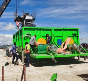
Modular Cement Grinding Plant
A modular cement grinding plant is a compact and flexible cement production solution developed in recent years for small and medium-sized but growing cement markets. Unlike traditional grinding plants, the modular system divides the complete grinding line into multiple standardized modules, allowing faster manufacturing, transportation, installation, and commissioning. For more detail please clinker here: What is a modular cement grinding plant?
Why Modular Cement Grinding Plants Are Invented?
Modular cement grinding plants were developed in response to the cement industry’s growing demand for faster, more flexible, and lower-cost production solutions. Traditional cement plants require large investments, long construction periods, and extensive civil works, making them less suitable for rapidly changing markets and remote project locations. As global clinker trade expanded, many investors began importing clinker and focusing only on local cement grinding and blending. This created demand for compact grinding systems that could be installed quickly and expanded easily. Based on this market background, modular cement grinding plants were introduced. By using standardized and pre-engineered modules for grinding, storage, dust collection, and packing systems, these plants significantly reduce installation time, construction costs, and project risks.
What are the features of a Modular Mobile Grinding Plant?
Through modular integration and containerized design, each unit can be pre-assembled before delivery, greatly reducing onsite civil work and installation time. The plant is especially suitable for local cement producers, market entrants, and construction companies seeking low investment, quick market entry, and flexible cement production capacity.
Adventages:
- Low capital investment and fast ROI
- Compact layout with reduced land occupation
- Short delivery and installation period
- Simple civil construction requirements
- Easy operation and maintenance
- Containerized modules for convenient transportation
- Flexible and movable production solution
- Fast disassembly and reassembly at different locations
- High pre-assembly rate reducing onsite work
- Lower transportation and storage costs of finished cement
- Energy-saving and efficient grinding system
- Suitable for producing multiple cement types
- Ideal for emerging and developing cement markets
Clinker Grinding Plant vs. Cement Plant: Which One Should You Invest In?
Clinker grinding plants only include cement grinding, storage, conveying, and packing systems, while integrated cement plants include the entire clinker production process such as raw material crushing, raw meal grinding, preheating, rotary kiln calcination, clinker cooling, and cement grinding. Because of this difference, the investment cost, operating cost, and plant scale are significantly different.
Invest in cement grinding plant:
Clinker grinding plants require lower initial investment, smaller installation area, lower electrical load, and fewer operators. However, these plants depend on external clinker supply and are more affected by clinker purchasing and transportation costs.
- Lower capital investment
- Shorter construction period
- Smaller land requirement
- Lower maintenance cost
- Lower manpower requirement
- Simpler process flow
- Easier capacity expansion
- Lower electrical and fuel consumption
- Suitable for regional cement markets near ports or clinker supply sources
Invest in cement plant:
Integrated cement plants require much larger capital investment and higher fuel and power consumption because clinker production is included. However, they can independently produce clinker and finished cement while achieving lower production cost per ton at large production capacity.
- Independent clinker production
- Lower cement production cost per ton at large scale
- Higher total production capacity
- Better control of raw material and cement quality
- Reduced dependence on external clinker suppliers
- Ability to produce multiple cement grades and specialty cement
- Better long-term profitability at high utilization rates
- More stable large-scale continuous production operation
Which one I should invest? Cement plant or cement grinding plant?
Clinker grinding plants are more suitable when the project requires lower investment, faster construction, smaller production scale, and simpler plant operation. Since these plants only perform cement grinding, the equipment configuration, maintenance workload, and infrastructure requirements are significantly reduced. However, production capacity is limited and clinker must be supplied externally. Integrated cement plants are more suitable for large-scale continuous cement production because they include both clinker manufacturing and cement grinding systems. Although the investment cost, fuel consumption, and operational complexity are much higher, these plants provide larger production capacity, lower long-term production cost per ton, and greater control over clinker and cement quality. In practical project planning, clinker grinding plants are commonly selected for regional cement distribution markets, coastal grinding terminals, or projects with limited investment budgets, while integrated cement plants are preferred for large industrial cement production bases with stable raw material supply and long-term production demand.
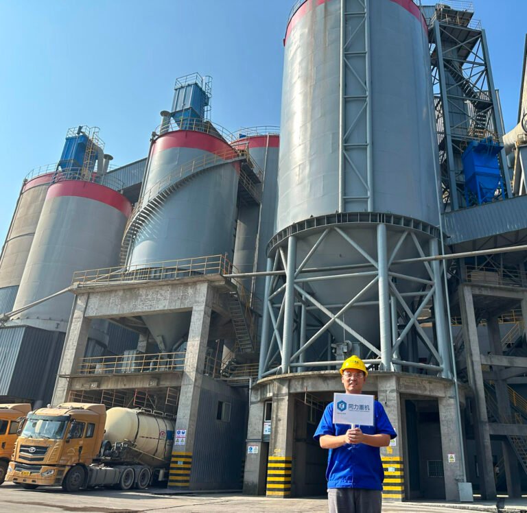
Cement Clinker Storage and Finished Cement Powder Storage Tips for Cement Grinding Plant Owner
In cement production, clinker storage is used to temporarily hold hot, hard clinker before grinding. The focus is on preventing lumping, controlling temperature, keeping the material dry, and ensuring a steady feed to the mill. In contrast, cement storage after grinding deals with fine, powdery cement that is prone to moisture absorption and hardening. Storage must carefully control humidity, prevent caking, and allow smooth discharge for packing or bulk loading. Finished cement powder inventory rarely exceeds one week's production at any given time. In contrast, clinker can be stored conveniently and economically to meet maximum demand.
FAQ: Frequently Asked Questions About Cement Grinding Plant Clinker Storage:
Cement grinding plants typically maintain a clinker inventory of 7 to 15 days based on daily consumption. For inland grinding plants relying on truck transport, 7 to 10 days' worth of inventory is sufficient; while coastal grinding plants relying on sea transport usually maintain an inventory equivalent to four to six weeks' production, but this may be reduced during peak demand periods and increased during off-peak periods to cope with unpredictable shipping schedules and large single-volume shipments.
International bulk carriers typically transport clinker in voyages of approximately 15,000 tons, which is the mainstream cargo volume for international clinker sea transport. The required clinker inventory varies significantly depending on the size of the grinding plant. Small grinding plants only need to store a few thousand tons of clinker, medium-sized grinding plants need approximately 10,000 to 20,000 tons or more, while large and super-large grinding plants are equipped with huge silos and storage yards, capable of storing 30,000 to 60,000 tons or more of clinker. Large grinding plants have higher daily clinker consumption, therefore their designs incorporate larger storage capacities to match their production and feed rates.
Although clinker is much more stable than finished cement, exposure to the environment can still cause a certain degree of deterioration. For this reason, clinker silos are typically designed as fully enclosed structures. Metered or batch-type clinker silos are particularly effective in preventing fine clinker dust pollution that occurs when clinker is stored outdoors.
Cement clinker is a high-temperature sintered material composed of silicate minerals, primarily tricalcium silicate (C₃S), dicalcium silicate (C₂S), tricalcium aluminate (C₃A), and ferrite (C₄AF). These minerals are inherently hydraulically active and not completely inert. When clinker comes into direct contact with rainwater or atmospheric moisture, surface pre-hydration occurs first. Active minerals at the clinker surface react prematurely with water, forming calcium hydroxide and hydrated calcium silicates. This process disrupts the originally dense, hard clinker particle structure, causing particles to become loose and friable and significantly reducing overall mechanical strength.
During subsequent grinding, pre-hydrated clinker exhibits abnormal grindability, increasing mill energy consumption, reducing grinding efficiency, and causing imbalances in cement particle size distribution. The clinker’s internal hydraulic active components are prematurely consumed, leading to a significant loss of reactivity. Cement produced from such clinker shows increased water demand at standard consistency, abnormal setting times, and reduced early and late compressive and flexural strengths, often failing to meet national cement strength standards and severely affecting its performance in construction applications.
Long-term outdoor exposure and moisture can also lead to clinker agglomeration, where hydrated particles stick together to form hard lumps. These clinker lumps are difficult to grind uniformly, leading to mill blockages and poor flow from the silo, disrupting production continuity. Furthermore, uneven chemical composition within lumps compromises the stability of finished cement.
Additionally, unprotected outdoor storage exposes clinker to rainwater runoff, which can carry soil, silt, and other impurities into the clinker pile. This contamination alters the clinker’s original chemical composition and loss on ignition, and disrupts the precise batching ratios in the grinding plant, causing key parameters such as SO₃ and MgO to exceed acceptable limits. As a result, finished cement exhibits significant variability in physical and chemical properties, making quality control difficult.
Even in high-humidity air without direct rain exposure, clinker gradually absorbs moisture and undergoes slow pre-hydration over time. This cumulative effect similarly reduces clinker reactivity and deteriorates cement quality. For this reason, in industrial practice, clinker must be stored in fully enclosed indoor silos, strictly isolated from moisture and atmospheric humidity—this is a core technical requirement to maintain clinker quality.
Clinker storage is typically designed for approximately 5–7 days of production demand, while also considering maintenance shutdowns, silo cleaning, material switching, and continuous production stability.
For a 25tph cement grinding plant, the clinker consumption under high-clinker-ratio operation is approximately 600 tons per day. Based on a 5-day storage period, the required clinker storage capacity is around 3,000 tons. Small grinding plants may adopt one large φ10m × 22m clinker silo with an effective storage capacity of approximately 1,500–2,000 tons, sometimes combined with an auxiliary buffer hopper. However, two-silo configurations are becoming increasingly common to improve operational flexibility and maintenance redundancy.
A 50tph cement grinding plant typically consumes approximately 1,200 tons of clinker per day, requiring around 6,000 tons of clinker storage for a 5-day storage cycle. The most common configuration consists of two φ10m × 22m clinker silos operating either in parallel or in duty-standby mode to ensure continuous feeding and simplify maintenance or silo cleaning operations. Some projects may also adopt one larger φ12m × 24m silo combined with a smaller auxiliary silo.
For a 75tph grinding plant, clinker consumption reaches approximately 1,800 tons per day, corresponding to around 9,000 tons of storage demand. Typical designs include two φ12m × 24m clinker silos with a combined effective capacity of approximately 8,000 tons, or alternatively three medium-sized silos to provide greater flexibility for maintenance, clinker homogenization, and multiple material sources. Therefore, 2–3 silos are commonly adopted for this capacity range.
A 100tph cement grinding plant generally consumes approximately 2,400 tons of clinker per day under high clinker ratio conditions. With a 5-day storage requirement, total clinker storage demand reaches approximately 12,000 tons. Standard engineering practice commonly adopts three φ12m × 24m clinker silos or two larger φ15m × 25m silos, depending on site layout, unloading logistics, and investment strategy.
For a 150tph grinding plant, clinker consumption may reach approximately 3,600 tons per day, requiring roughly 18,000 tons of clinker storage capacity. Mainstream designs usually adopt four φ12m × 24m clinker silos or three larger φ15m × 25m silos. In some projects, additional outdoor clinker stockpiles are also used as supplementary storage to enhance supply stability and reduce logistics risks.
Normnally cement grinding plants use multiple additive material silos to store gypsum, fly ash, limestone powder, slag powder, pozzolan and other supplementary cementitious materials separately. Unlike clinker silos or finished cement silos, the number of additive silos is not mainly determined by grinding plant capacity, but rather by the variety of cement products, blending formulations, and material switching requirements. In actual engineering practice, each major additive is usually stored in an independent silo to avoid material contamination, improve dosing accuracy, and support stable cement quality control.
For basic OPC cement grinding plants with relatively simple formulations, the additive storage system may only require 2–3 silos, typically including one gypsum silo and one or two supplementary material silos for limestone powder or fly ash. However, for modern PPC, PCC, PSC, and composite cement grinding plants, the number of additive silos usually increases to 3–5 silos in order to separately store gypsum, fly ash, slag powder, limestone powder and other blended materials. This configuration has become the most common arrangement in today’s cement grinding industry.
In recent years, with the rapid development of low-carbon cement and blended cement technologies, many grinding plants have started producing LC3 cement, slag cement, steel slag cement and other environmentally friendly cement products. These projects often require additional storage silos for calcined clay, steel slag powder, pozzolan or specialty additives. As a result, advanced modern grinding plants may adopt 5–8 additive silos or even more to support multi-product production, rapid recipe switching and independent material dosing systems.
There is no fixed standard for the planned area of clinker storage yards at cement grinding stations. It is typically determined based on a comprehensive consideration of factors such as the hourly output of the production line, daily clinker consumption, storage period, stacking height, vehicle access, and loading/unloading space. Rather than simply calculating based on storage capacity in tons, engineering design often uses the "total planned area" to reflect actual land requirements. This is because the storage yard not only needs to accommodate clinker storage but also requires provisions for loader operations, truck unloading, road access, drainage systems, and future expansion space. Generally, a small 25tph cement grinding station requires approximately 1200–1500 square meters of clinker storage yard; a 50tph production line typically requires 2000–2500 square meters; a medium-sized 75tph grinding station requires approximately 3200–3800 square meters; a 100tph large-scale grinding station typically requires 4500–5200 square meters; while large grinding stations of 150tph and above often require 6500–7500 square meters or even more to meet the needs of large-scale continuous production and clinker storage. With increasingly stringent environmental protection requirements, projects with a capacity of 75 tph or more are increasingly inclined to adopt semi-enclosed or fully enclosed clinker storage sheds to reduce dust pollution and improve the stability of raw material storage.
For a typical cement grinding plant slag storage yard, a 25tph grinding station usually requires a clinker yard size of approximately 40m × 35m. A 50tph grinding plant generally requires around 55m × 40m. For a 75tph grinding plant, the clinker storage yard is commonly designed at approximately 70m × 50m. A 100tph cement grinding plant typically requires about 85m × 60m, while a large 150tph grinding plant usually adopts a clinker yard size of approximately 100m × 70m. These dimensions normally include clinker stacking area, loader operating space, truck access roads, unloading area, and basic operational clearance.
FAQ: Frequently Asked Questions About Cement Grinding Plant Cement Powder Storage:
Because cement clinker has a long storage life and can be transported using conventional bulk granular materials, grinding is not required at the production plant. Clinker can be allocated between plants to match production or meet local demand; it can also be transported to grinding plants without kilns, typically located in areas with high local demand but a lack of raw materials for clinker production. A significant portion of international cement import and export trade is conducted in the form of clinker rather than finished products.
The storage and temporary storage methods for finished cement can be mainly divided into three major modes: bulk silo storage, bagged cement storage, and direct shipment. Different methods correspond to different production scales, sales models, and logistics needs.
Firstly, there is finished cement silo storage, which is the most core and common storage method in modern cement grinding stations and cement plants. Freshly ground bulk cement is directly fed into sealed steel silos or concrete finished product silos for short-term storage via air chutes, elevators, or pneumatic conveying systems. These silos are typically equipped with aeration unloading systems, dust removal systems, material level monitoring systems, and homogenization devices, enabling automated storage and shipment management. Their main functions are to meet production turnover, homogenization and blending of different cement components, shipment buffering, and short-term stockpiling needs. Because cement is a highly hygroscopic powder, long-term storage can easily lead to problems such as moisture absorption, clumping, strength reduction, and false setting. Therefore, finished product silos are more suitable for short-cycle dynamic storage; the industry typically designs them for 7-10 days of storage capacity, while large ports or seasonal markets may appropriately extend the storage period.
Secondly, there is bagged cement storage. After cement is packaged into standard bags by a packaging machine, it is transferred to a dedicated finished product warehouse for storage. Compared to bulk silos, bagged warehouses offer better protection against air moisture and rain, making them more suitable for retail stocking, small-batch sales, and regional distribution. Bagged warehouses typically require good ventilation, moisture-proofing, rain protection, and ground moisture-proofing measures. Bagged cement is generally stacked on pallets or flat to reduce the risk of moisture absorption at the bottom. In developing countries and rural markets primarily serving the civilian market, bagged cement still accounts for a significant proportion; therefore, many small and medium-sized grinding stations have dedicated bagged finished product warehouses and packaging/shipping areas.
The third method is direct loading and shipment, also known as the "production-as-you-go" model. After passing production, bulk cement is directly loaded from the finished product warehouse into bulk cement tankers using a bulk loading machine. Bagged cement is loaded directly onto trucks using an automated loading system or manual forklifts for shipment, minimizing intermediate storage time. This model is very common in large cement plants, port grinding stations, and commercial concrete grinding projects, especially suitable for regions with stable market demand, well-developed logistics systems, and a high proportion of bulk cement. Due to the short residence time of cement, the risks of moisture absorption, clumping, and performance degradation are minimized, while also reducing inventory capital occupation and warehousing management costs.
In addition to the three mainstream methods mentioned above, the modern cement industry has gradually developed some special storage forms. For example, port transshipment steel silos are mainly used for large-scale transshipment storage of imported clinker or exported cement, typically equipped with large pneumatic conveying and bulk loading systems; modular containerized storage systems are mainly used in overseas modular grinding stations, remote area projects, and temporary engineering projects, featuring convenient transportation, rapid installation, and relocation capabilities; while small bulk silos are widely used in commercial concrete plants, engineering plants, and mobile construction projects for short-term, small-scale cement storage.
Cement grinding plants are commonly designed with finished cement storage equivalent to approximately 7–10 days of production capacity, although the actual value may vary depending on market conditions, transportation logistics, and seasonal demand fluctuations.
For a small 25tph cement grinding plant, the daily output is approximately 600 tons. Based on a 7-day storage cycle, the required finished cement storage is around 4,200 tons, while a 10-day cycle requires approximately 6,000 tons. Since small grinding stations usually focus on local civil markets with relatively limited cement varieties, they are commonly equipped with 2 finished cement silos. These are typically used for ordinary Portland cement and blended cement storage, which is generally sufficient for normal production and sales turnover.
A 50tph medium-small grinding plant can produce approximately 1,200 tons per day, corresponding to about 8,400–12,000 tons of storage capacity for a 7–10 day cycle. Because these plants usually serve larger regional markets with more cement grades and specifications, the typical configuration is 2–3 silos, with 3 silos being the most common arrangement. Two silos are generally allocated to mainstream cement grades such as OPC and PPC, while the remaining silo serves as a buffer or standby silo for maintenance, product switching, or temporary storage adjustment.
For a 75tph medium-sized mainstream grinding station, daily production reaches approximately 1,800 tons, requiring around 12,600–18,000 tons of storage capacity. These plants generally cover wider market areas and produce a broader range of cement products. Therefore, 3–4 silos are commonly configured, with 4 silos considered a standard design solution. This arrangement enables separated storage of multiple cement grades while also providing additional buffer space for peak-season inventory buildup and operational flexibility.
Large 100tph cement grinding plants usually serve broader external markets and operate with multiple cement types and dispatch modes. Due to the higher requirements for storage flexibility and logistics management, these plants are typically equipped with 4–6 finished cement silos. The silos are often divided into dedicated functions such as multi-grade storage silos, bulk cement dispatch silos, bagged cement storage silos, and emergency buffer silos. This configuration supports both bulk and bagged cement sales while ensuring efficient coordination between production, storage, and seasonal shipment demands.
Finished cement can be transported using a variety of methods, but pneumatic systems are by far the most widely used. This is because cement, like other dry bulk powders, behaves almost like a fluid when suspended in air. In one common type of pneumatic conveyor, air is used primarily to regulate the particle size of the cement, allowing it to flow by gravity. In another system, air fluidizes the cement and propels it through pipelines, enabling both horizontal and vertical transportation.
Within a plant, short-distance cement transport relies mainly on air chutes, bucket elevators, belt conveyors, and screw conveyors. Air chutes are typically used for moving small amounts of cement powder over short distances, while vertical movement is handled by bucket elevators. Screw conveyors are often employed for small auxiliary material transfers.
For storage and external dispatch, finished cement transport varies depending on the scale and logistics of the plant. The most common method is pneumatic bulk cement transport. Here, cement is discharged from the silo bottom using a pneumatic unloading system, directly loading bulk cement trucks or ships. This method is the most efficient and represents the core logistics solution for cement grinding plants. Bagged cement is transported differently: after being packaged, it is moved by belt conveyors to a finished goods yard and then transferred by forklifts or trucks for delivery. Some plants also use enclosed belt conveyors for short-distance internal transfers of both bagged and bulk materials.
In addition, large grinding plants located near waterways may be equipped with terminal pneumatic ship-loading systems, allowing finished cement to be transported via pipelines directly into bulk cargo ships for large-scale waterway shipments. Smaller or remote plants often use compact scraper conveyors to handle simplified on-site transfer operations.
Firstly, the air inside the cement silo has a certain humidity level. The poor air circulation within the sealed silo causes cement particles to continuously absorb moisture, slowly undergoing a pre-hydration reaction. This leads to slight clumping, arching, and compaction, making it highly susceptible to silo blockage and poor material flow during later unloading. Prolonged static storage also causes the cement's own cementitious activity to gradually decrease, resulting in a decline in various mechanical properties. This leads to substandard strength and abnormal setting time after leaving the factory, directly impacting the quality of the cement used in the project. Furthermore, long-term static accumulation of cement in the silo causes severe compaction of the bottom layer, reducing material uniformity and making it impossible to guarantee consistent quality of the cement leaving the silo. Additionally, long-term occupation of silo space reduces the turnover efficiency of the grinding production line, affecting normal continuous production and finished product sales. Therefore, cement grinding stations only use finished product silos for short-term turnover storage and do not store finished cement in the silos for extended periods.
How Large Should the Clinker and GGBS Storage Yard Be When Using Vessel Transportation in a Cement Grinding Plant?
If cement grinding plants primarily source clinker by sea, the planning logic for clinker storage yards changes significantly. Many port-type grinding plants typically receive clinker shipments of 10,000 to 30,000 tons at a time, while small and medium-sized projects often use a single-ship procurement model of approximately 15,000 tons. In this case, the storage yard size is no longer designed solely based on "grinding plant's daily output × storage days," but must prioritize "single-ship receiving capacity." Even a small grinding line of 50 tph or even 25 tph, if it purchases clinker by the entire ship, often requires a large clinker storage yard; otherwise, unloading the entire ship cannot be completed, resulting in very high port demurrage fees. Therefore, many port grinding plants exhibit a situation where "output is not large, but clinker storage yards are large," essentially because the logistics model determines the storage yard size, rather than simply production capacity For projects receiving 15,000 tons of clinker at a time, if a conventional open-air or semi-enclosed strip stockpile is used with a stacking height of approximately 8-10 meters, a stockpile area of about 4,500-6,000 square meters is typically required. Typical dimensions are approximately 80m × 60m, 90m × 60m, or 100m × 50m. This area includes not only the clinker storage area but also provisions for loader operation areas, vehicle access, unloading areas, and safety clearances. If a fully enclosed circular storage shed or mechanized stacker-reclaimer system is used, the land use will change further. However, the logic for GGBS slag powder or slag raw materials is different. If slag is continuously transported to the plant by truck with a stable supply, a particularly large stockpile is usually unnecessary. This is because truck transportation operates on a "small batch, high frequency" continuous replenishment model, with the core objective being to ensure production continuity, rather than storing large quantities of material at once. In this case, the slag system typically only needs a transit warehouse, a small storage shed, or a raw material silo for a few days' worth of use to meet production needs. However, if slag is also transported by sea, rail, or through centralized procurement, a large stockpile needs to be planned based on the total volume of shipments. For example, when a project needs to store 15,000 tons of slag raw materials at once, considering that the bulk density of slag is usually lower than that of clinker and the stockpile is looser, a stockpile area of approximately 5,500 to 7,000 square meters is typically required under normal stockpile height conditions. Typical dimensions are approximately 90m × 70m, 100m × 65m, or 110m × 60m. Large-scale GGBS projects will also be equipped with enclosed slag stockpiles, bridge scraper reclaimers, and automated conveying systems to improve environmental performance and continuous supply capacity.
Should Finished Cement Be Stored in Steel Silos or Concrete Silos?
Finished cement is generally preferred to be stored in reinforced concrete silos, while steel silos are more suitable for short-term temporary storage and rapid turnover applications. In traditional cement plant design, finished cement storage silos are commonly constructed using reinforced concrete structures because of their superior weather resistance and high sealing performance. Even so, the storage period is usually kept as short as possible, and silo capacity is often designed to correspond to approximately two weeks of production output. During storage, cement tends to settle and compact, so air fluidization systems are required to aerate the material and ensure smooth discharge from the silo for bulk loading or bagging operations. For detailed comparison of whether to use a concrete silo or steel silo please click here: Concrete Silo vs Steel Silo for Cement Storage: Which Is Better for Cement Powder?
Why use concrete silo?
Reinforced concrete silos have thick walls with excellent thermal insulation and moisture resistance properties. The internal silo temperature remains relatively stable and is less affected by external temperature fluctuations and humidity, which helps reduce cement moisture absorption and premature hydration. This effectively slows down cement activity loss and lump formation during storage. In addition, concrete silos have high structural strength and load-bearing capacity, making them more suitable for long-term bulk storage without severe material compaction, silo deformation, or excessive caking problems. Their superior sealing and insulation performance make them the most commonly adopted solution for finished cement storage in traditional cement grinding plants.
Why use steel silo?
Steel silos, on the other hand, are lighter in weight, faster to construct, and generally require lower initial investment. However, steel plates conduct heat rapidly, and under large day-night temperature differences, condensation can easily form on the inner wall of the silo. This may cause cement moisture absorption, deterioration, and quality reduction. Furthermore, due to the smooth inner surface, cement tends to form arching and bridging after static storage, leading to discharge blockage problems. Steel structures are also more vulnerable to corrosion, which can negatively affect the storage environment over time. Therefore, steel silos are generally more suitable for small-capacity production lines with extremely fast turnover and very short storage periods, rather than for long-term main finished cement storage applications.
How to Improve Efficiency in Cement Grinding Plant? 12 Tips
Improving grinding efficiency in a cement grinding plant is not only about increasing mill output, but also about reducing specific power consumption, stabilizing cement quality, and optimizing particle size distribution.
1. Reduce Clinker Feed Size Before Final Grinding
Large clinker particles significantly increase grinding difficulty and power consumption. Many cement plants install vertical roller mill systems ahead of the ball mill to pre-crush clinker and generate internal micro-cracks inside the particles. These cracks weaken the clinker structure and improve downstream grinding efficiency, reducing the load on the cement mill.
2. Optimize Ball Mill Grinding Media Grading
Grinding media size distribution directly affects grinding performance. The first chamber should use larger balls for impact crushing of coarse particles, while smaller balls are used in later chambers for fine grinding. Incorrect media grading often leads to excessive over-grinding, low output, and high electricity consumption. Grinding media wear should be monitored regularly, and periodic recharging is necessary to maintain stable mill efficiency.
3. Control Cement Particle Size Distribution Properly
Cement fineness should not simply pursue higher specific surface area. Excessive ultra-fine particles below 3 μm increase power consumption and water demand, while excessive coarse particles above 45 μm reduce cement strength. In practical operation, controlling both 45 μm sieve residue and Blaine surface area within a reasonable range helps optimize cement performance while reducing grinding energy consumption.
4. Improve Separator Efficiency and Reduce Circulating Load
In closed-circuit grinding systems, separator efficiency directly determines mill performance. A low-efficiency separator returns too many fine particles back to the mill, causing over-grinding and unnecessary energy consumption. High-efficiency dynamic separators improve classification accuracy and reduce circulating load. Separator rotor speed, airflow volume, and guide vane settings should be optimized according to cement fineness requirements.
5. Keep stable Material Moisture and Mill Temperature
High moisture content causes material coating inside the mill and separator, reducing grinding efficiency and affecting ventilation. Excessive grinding temperature may also cause gypsum dehydration and abnormal cement setting time. Proper ventilation, hot gas control, and stable material moisture are essential for efficient grinding operation. VRM systems have an advantage because drying and grinding occur simultaneously inside the mill.
6. Improve Mill Ventilation and Reduce False Air Leakage
Proper airflow removes fine particles from the grinding zone quickly and improves material transport inside the mill. Poor ventilation increases material accumulation and mill temperature, while excessive airflow may reduce separation efficiency. False air leakage from mill seals, ducts, bag filters, and expansion joints increases fan power consumption and destabilizes system pressure.
7. Use Grinding Aids Properly
Grinding aids reduce particle agglomeration and coating inside the mill. By improving powder dispersion, grinding aids can increase mill output, improve cement particle distribution, and reduce specific energy consumption. In many plants, proper grinding aid dosage can increase the proportion of 3–30 μm cement particles by 10–20%, which is beneficial for cement strength development.
8. Optimize Internal Mill Structure and Screening System
High-efficiency diaphragms, lifting liners, classification liners, and forced screening systems improve material flow and grinding performance inside the mill. In many retrofit projects, mill output can increase by 30%–60%, while system power consumption may decrease by 25%–40%, reducing electricity consumption by 8–12 kWh per ton of cement. Cement strength can also improve by more than 5 MPa.
9. Use Variable Frequency Drive (VFD) Technology
Variable frequency drives (VFDs) are widely used in fans, separators, feeders, and auxiliary drive systems. VFD systems allow continuous speed adjustment according to process conditions, reducing unnecessary power consumption and improving process stability. They also provide smooth motor startup with lower inrush current and reduced mechanical stress on equipment.
10. Improve Power Factor and Electrical Efficiency
Electrical optimization also contributes to grinding efficiency improvement. Technologies such as automatic motor load control, high-efficiency motors, reactive power compensation, and optimized electrical systems reduce power losses and improve overall plant energy utilization. Some motor control systems can reduce motor energy consumption by approximately 15% under variable load conditions.
11. Utilize Industrial By-products
The use of blast furnace slag, fly ash, steel slag, and other supplementary cementitious materials can improve cement properties while reducing clinker factor and grinding energy consumption. Proper material blending can reduce overall grinding difficulty and lower production cost while producing environmentally friendly low-carbon cement products.
12. Maintain Stable Feed Rate and Material Composition
Frequent fluctuations in clinker ratio, gypsum content, slag proportion, or feed quantity destabilize mill operation and separator performance. Stable weighing systems, constant feeding equipment, and automated process control is the key to master stable operation and stable product quality.
Configurations of cement grinding plant
150,000 t/a GGBS Slag Powder Cement Grinding Plant Configuration
| No. | Item | 150,000 t/a Slag Powder Production Line |
| 1 | Slag vertical roller mill | Model: ZJTL2220 Capacity: ≥20 t/h Specific surface area: ≥420m²/kg Power: 630 kW |
| 2 | Hot-blast stove | Heating capacity: 0.4×10⁷ kcal/h |
| 3 | Dust collector | Airflow: 80000 m³/hFilter area: 1594 m²Filtration velocity: 0.80~0.85 m/minInlet dust concentration: ≤800 g/Nm³Outlet dust concentration: ≤30 mg/Nm³ |
| 4 | Main exhaust fan | Airflow: 80000 m³/hTotal pressure: 7200 PaPower: 220 kW |
| 5 | Bucket elevator | NE100 / NE150 |
| 6 | Belt conveyor | B650 / B800 |
| 7 | Product silo | 2×1000 t (optional) |
| 8 | Packing machine | Rotary packer / bulk loading system |
| 9 | Electrical control system | PLC automatic control system |
Remarks:
- Factory capacity: 150×10³ t/a
- Main raw material: Granulated blast furnace slag (150000 t/a)
- Gypsum/additives can be adjusted according to product formula requirements
- Product fineness (specific surface area): ≥420 m²/kg
- Product moisture content: ≤1%
- Electrical consumption: Approx. 8.0×10⁶ kWh/a
- Hot air consumption: 0.4×10⁷ kcal/h
- Land area required: Approx. 18000~22000 ㎡
- Number of workers: 25~35 persons
30tph Cement Grinding Plant Configuration
| No. | Item | 200,000 t/a Slag Powder Production Line |
| 1 | Slag vertical roller mill | Model: ZJTLK2520 Capacity: ≥28 t/h Specific surface area: ≥420m²/kg Power: 900 kW |
| 2 | Hot-blast stove | Heating capacity: 0.5×10⁷ kcal/h |
| 3 | Dust collector | Airflow: 112000 m³/hFilter area: 2196 m²Filtration velocity: 0.80~0.85 m/minInlet dust concentration: ≤800 g/Nm³Outlet dust concentration: ≤30 mg/Nm³ |
| 4 | Main exhaust fan | Airflow: 112000 m³/hTotal pressure: 7200 PaPower: 315 kW |
| 5 | Bucket elevator | NE150 / NE200 |
| 6 | Belt conveyor | B800 |
| 7 | Product silo | 2×1500 t (optional) |
| 8 | Packing machine | Rotary packer / bulk loading system |
| 9 | Electrical control system | PLC automatic control system |
Remarks:
- Factory capacity: 200×10³ t/a
- Main raw material: Granulated blast furnace slag (200000 t/a)
- Gypsum/additives can be adjusted according to product formula requirements
- Product fineness (specific surface area): ≥420 m²/kg
- Product moisture content: ≤1%
- Electrical consumption: Approx. 1.1×10⁷ kWh/a
- Hot air consumption: 0.5×10⁷ kcal/h
- Land area required: Approx. 20000~24000 ㎡
- Number of workers: 25~35 persons
45tph Cement Grinding Plant Configuration
| No. | Item | 300,000 t/a Slag Powder Production Line |
| 1 | Slag vertical roller mill | Model: ZJTLK3630 Capacity: ≥45 t/h Specific surface area: ≥420m²/kg Power: 1600 kW |
| 2 | Hot-blast stove | Heating capacity: 0.9×10⁷ kcal/h |
| 3 | Dust collector | Airflow: 180000 m³/hFilter area: 3659 m²Filtration velocity: 0.80~0.85 m/minInlet dust concentration: ≤800 g/Nm³Outlet dust concentration: ≤30 mg/Nm³ |
| 4 | Main exhaust fan | Airflow: 180000 m³/hTotal pressure: 7200 PaPower: 500 kW |
| 5 | Bucket elevator | NE200 / NE300 |
| 6 | Belt conveyor | B1000 |
| 7 | Product silo | 2×2000 t (optional) |
| 8 | Packing machine | Rotary packer / bulk loading system |
| 9 | Electrical control system | PLC automatic control system |
Remarks:
- Factory capacity: 300×10³ t/a
- Main raw material: Granulated blast furnace slag (300000 t/a)
- Gypsum/additives can be adjusted according to product formula requirements
- Product fineness (specific surface area): ≥420 m²/kg
- Product moisture content: ≤1%
- Electrical consumption: Approx. 1.6×10⁷ kWh/a
- Hot air consumption: 0.9×10⁷ kcal/h
- Land area required: Approx. 24000~28000 ㎡
- Number of workers: 25~35 persons
65tph Cement Grinding Station Configuration
| No. | Item | 500,000 t/a Slag Powder Production Line |
| 1 | Slag vertical roller mill | Model: ZJTL3700 Capacity: ≥65 t/h Specific surface area: ≥420m²/kg Power: 2000 kW |
| 2 | Hot-blast stove | Heating capacity: 1.3×10⁷ kcal/h |
| 3 | Dust collector | Airflow: 260000 m³/hFilter area: 5352 m²Filtration velocity: 0.80~0.85 m/minInlet dust concentration: ≤800 g/Nm³Outlet dust concentration: ≤30 mg/Nm³ |
| 4 | Main exhaust fan | Airflow: 260000 m³/hTotal pressure: 7200 PaPower: 710 kW |
| 5 | Bucket elevator | NE300 |
| 6 | Belt conveyor | B1000 |
| 7 | Product silo | 2×3000 t (optional) |
| 8 | Packing machine | Rotary packer / bulk loading system |
| 9 | Electrical control system | PLC automatic control system |
Remarks:
- Factory capacity: 500×10³ t/a
- Main raw material: Granulated blast furnace slag (500000 t/a)
- Gypsum/additives can be adjusted according to product formula requirements
- Product fineness (specific surface area): ≥420 m²/kg
- Product moisture content: ≤1%
- Electrical consumption: Approx. 2.5×10⁷ kWh/a
- Hot air consumption: 1.3×10⁷ kcal/h
- Land area required: Approx. 25000~29000 ㎡
- Number of workers: 25~35 persons
75tph Cement Grinding Unit Configuration
| No. | Item | 600,000 t/a Slag Powder Production Line |
| 1 | Slag vertical roller mill | Model: ZJTL3840 Capacity: ≥75 t/h Specific surface area: ≥420m²/kg Power: 2500 kW |
| 2 | Hot-blast stove | Heating capacity: 1.5×10⁷ kcal/h |
| 3 | Dust collector | Airflow: 300000 m³/hFilter area: 6116 m²Filtration velocity: 0.80~0.85 m/minInlet dust concentration: ≤800 g/Nm³Outlet dust concentration: ≤30 mg/Nm³ |
| 4 | Main exhaust fan | Airflow: 300000 m³/hTotal pressure: 7200 PaPower: 800 kW |
| 5 | Bucket elevator | NE50 |
| 6 | Belt conveyor | B1000 |
| 7 | Product silo | 2×5000 t (optional) |
| 8 | Packing machine | Rotary packer / bulk loading system |
| 9 | Electrical control system | PLC automatic control system |
Remark:
- Factory capacity: 600×10³ t/a
- Main raw material: Granulated blast furnace slag (600000 t/a)
- Gypsum/additives can be adjusted according to product formula requirements
- Product fineness (specific surface area): ≥420 m²/kg
- Product moisture content: ≤1%
- Electrical consumption: Approx. 3.0×10⁷ kWh/a
- Hot air consumption: 1.5×10⁷ kcal/h
- Land area required: Approx. 25000~29000 ㎡
- Number of workers: 25~35 persons
90tph Cement Grinding Plant Configuration
| No. | Item | 800,000 t/a Slag Powder Production Line |
| 1 | Slag vertical roller mill | Model: ZJTL4230 Capacity: ≥90 t/h Specific surface area: ≥420m²/kg Power: 3150 kW |
| 2 | Hot-blast stove | Heating capacity: 1.8×10⁷ kcal/h |
| 3 | Dust collector | Airflow: 360000 m³/hFilter area: 7319 m²Filtration velocity: 0.80~0.85 m/minInlet dust concentration: ≤800 g/Nm³Outlet dust concentration: ≤30 mg/Nm³ |
| 4 | Main exhaust fan | Airflow: 360000 m³/hTotal pressure: 7200 PaPower: 1000 kW |
| 5 | Bucket elevator | NE50 |
| 6 | Belt conveyor | B1000 |
| 7 | Product silo | 2×5000 t (optional) |
| 8 | Packing machine | Rotary packer / bulk loading system |
| 9 | Electrical control system | PLC automatic control system |
Remark:
- Factory capacity: 800×10³ t/a
- Main raw material: Granulated blast furnace slag (800000 t/a)
- Gypsum/additives can be adjusted according to product formula requirements
- Product fineness (specific surface area): ≥420 m²/kg
- Product moisture content: ≤1%
- Electrical consumption: Approx. 4.0×10⁷ kWh/a
- Hot air consumption: 1.8×10⁷ kcal/h
- Land area required: Approx. 26000~30000 ㎡
- Number of workers: 25~30 persons
120tph Cement Grinding Plant Configuration
| No. | Item | 1,000,000 t/a Slag Powder Production Line |
| 1 | Slag vertical roller mill | Model: ZJTL4640 Capacity: ≥115 t/h Specific surface area: ≥420m²/kg Power: 3550 kW |
| 2 | Hot-blast stove | Heating capacity: 2.3×10⁷ kcal/h |
| 3 | Dust collector | Airflow: 460000 m³/hFilter area: 8782 m²Filtration velocity: 0.80~0.85 m/minInlet dust concentration: ≤800 g/Nm³Outlet dust concentration: ≤30 mg/Nm³ |
| 4 | Main exhaust fan | Airflow: 460000 m³/hTotal pressure: 7200 PaPower: 1250 kW |
| 5 | Bucket elevator | NE50 |
| 6 | Belt conveyor | B1000 |
| 7 | Product silo | 2×5000 t (optional) |
| 8 | Packing machine | Rotary packer / bulk loading system |
| 9 | Electrical control system | PLC automatic control system |
Remark:
- Factory capacity: 1000×10³ t/a
- Main raw material: Granulated blast furnace slag (1000000 t/a)
- Gypsum/additives can be adjusted according to product formula requirements
- Product fineness (specific surface area): ≥420 m²/kg
- Product moisture content: ≤1%
- Electrical consumption: Approx. 5.0×10⁷ kWh/a
- Hot air consumption: 2.3×10⁷ kcal/h
- Land area required: Approx. 26000~30000 ㎡
- Number of workers: 25~35 persons
130tph Cement Grinding Plant Configuration
| No. | Item | 1,200,000 t/a Slag Powder Production Line |
| 1 | Slag vertical roller mill | Model: ZJTL5030 Capacity: ≥130 t/h Specific surface area: ≥420m²/kg Power: 4000 kW |
| 2 | Hot-blast stove | Heating capacity: 2.6×10⁷ kcal/h |
| 3 | Dust collector | Airflow: 520000 m³/hFilter area: 10873 m²Filtration velocity: 0.80~0.85 m/minInlet dust concentration: ≤800 g/Nm³Outlet dust concentration: ≤30 mg/Nm³ |
| 4 | Main exhaust fan | Airflow: 520000 m³/hTotal pressure: 7200 PaPower: 1400 kW |
| 5 | Bucket elevator | NE50 |
| 6 | Belt conveyor | B1000 |
| 7 | Product silo | 3×5000 t (optional) |
| 8 | Packing machine | Rotary packer / bulk loading system |
| 9 | Electrical control system | PLC automatic control system |
Remark:
- Factory capacity: 1200×10³ t/a
- Main raw material: Granulated blast furnace slag (1200000 t/a)
- Gypsum/additives can be adjusted according to product formula requirements
- Product fineness (specific surface area): ≥420 m²/kg
- Product moisture content: ≤1%
- Electrical consumption: Approx. 6.0×10⁷ kWh/a
- Hot air consumption: 2.6×10⁷ kcal/h
- Land area required: Approx. 27000~30000 ㎡
- Number of workers: 25~35 persons
140tph Cement Grinding Plant Configuration
| No. | Item | 1,500,000 t/a Slag Powder Production Line |
| 1 | Slag vertical roller mill | Model: ZJTL5340 Capacity: ≥140 t/h Specific surface area: ≥420m²/kg Power: 4500 kW |
| 2 | Hot-blast stove | Heating capacity: 2.8×10⁷ kcal/h |
| 3 | Dust collector | Airflow: 560000 m³/hFilter area: 10873 m²Filtration velocity: 0.80~0.85 m/minInlet dust concentration: ≤800 g/Nm³Outlet dust concentration: ≤30 mg/Nm³ |
| 4 | Main exhaust fan | Airflow: 560000 m³/h Total pressure: 7200 Pa Power: 1600 kW |
| 5 | Bucket elevator | NE100 |
| 6 | Belt conveyor | B1200 |
| 7 | Product silo | 3×5000 t (optional) |
| 8 | Packing machine | Rotary packer / bulk loading system |
| 9 | Electrical control system | PLC automatic control system |
Remark:
- Factory capacity: 1500×10³ t/a
- Main raw material: Granulated blast furnace slag (1500000 t/a)
- Gypsum/additives can be adjusted according to product formula requirements
- Product fineness (specific surface area): ≥420 m²/kg
- Product moisture content: ≤1%
- Electrical consumption: Approx. 7.0×10⁷ kWh/a
- Hot air consumption: 2.8×10⁷ kcal/h
- Land area required: Approx. 27000~30000 ㎡
- Number of workers: 25~35 persons |
180tph Cement Grinding Plant Configuration
| No. | Item | 1,800,000 t/a Slag Powder Production Line |
| 1 | Slag vertical roller mill | Model: ZJTL 5640 Capacity: ≥180 t/h Specific surface area: ≥420m²/kg Power: 5400 kW |
| 2 | Hot-blast stove | Heating capacity: 3.4×10⁷ kcal/h |
| 3 | Dust collector | Airflow: 680000 m³/h Filter area: 13592 m² Filtration velocity: 0.80~0.85 m/minInlet dust concentration: ≤800g/Nm³ Outlet dust concentration: ≤30 mg/Nm³ |
| 4 | Main exhaust fan | Airflow: 680000 m³/hTotal pressure: 7200 PaPower: 1800 kW |
| 5 | Bucket elevator | NE100 |
| 6 | Belt conveyor | B1200 |
| 7 | Product silo | 3×5000 t (optional) |
| 8 | Packing machine | Rotary packer / bulk loading system |
| 9 | Electrical control system | PLC automatic control system |
Remark:
- Factory capacity: 1800×10³ t/a
- Main raw material: Granulated blast furnace slag (1800000 t/a)
- Gypsum/additives can be adjusted according to product formula requirements
- Product fineness (specific surface area): ≥420 m²/kg
- Product moisture content: ≤1%
- Electrical consumption: Approx. 8.5×10⁷ kWh/a
- Hot air consumption: 3.4×10⁷ kcal/h
- Land area required: Approx. 30000~35000 ㎡
- Number of workers: 25~35 persons |
220tph Cement Grinding Plant Configuration
| No. | Item | 2,000,000 t/a Slag Powder Production Line |
| 1 | Slag vertical roller mill | Model: ZJTL6230 Capacity: ≥210 t/h Specific surface area: ≥420m²/kg Power: 6500 kW |
| 2 | Hot-blast stove | Heating capacity: 3.4×10⁷ kcal/h |
| 3 | Dust collector | Airflow: 840000 m³/h Filter area: 16310 m² Filtration velocity: 0.80~0.85 m/min Inlet dust concentration: ≤800 g/Nm³ Outlet dust concentration: ≤30 mg/Nm³ |
| 4 | Main exhaust fan | Airflow: 840000 m³/hTotal pressure: 7200 PaPower: 2240 kW |
| 5 | Bucket elevator | NE100 |
| 6 | Belt conveyor | B1200 |
| 7 | Product silo | 4×5000 t (optional) |
| 8 | Packing machine | Rotary packer / bulk loading system |
| 9 | Electrical control system | PLC automatic control system |
Remark:
- Factory capacity: 2000×10³ t/a
- Main raw material: Granulated blast furnace slag (2000000 t/a)
- Gypsum/additives can be adjusted according to product formula requirements
- Product fineness (specific surface area): ≥420 m²/kg
- Product moisture content: ≤1%
- Electrical consumption: Approx. 1.0×10⁸ kWh/a
- Hot air consumption: 3.4×10⁷ kcal/h
- Land area required: Approx. 30000~35000 ㎡
- Number of workers: 25~35 persons |
250tph Cement Grinding Plant Configuration
| No. | Item | 2,500,000 t/a Slag Powder Production Line |
| 1 | Slag vertical roller mill | Model: ZJTL6640 Capacity: ≥250 t/h Specific surface area: ≥420m²/kg Power: 8000 kW |
| 2 | Hot-blast stove | Heating capacity: 5.0×10⁷ kcal/h |
| 3 | Dust collector | Airflow: 1000000 m³/hFilter area: 19880 m²Filtration velocity: 0.80~0.85 m/minInlet dust concentration: ≤800 g/Nm³Outlet dust concentration: ≤30 mg/Nm³ |
| 4 | Main exhaust fan | Airflow: 1000000 m³/hTotal pressure: 7200 PaPower: 2800 kW |
| 5 | Bucket elevator | NE100 |
| 6 | Belt conveyor | B1200 |
| 7 | Product silo | 5×5000 t (optional) |
| 8 | Packing machine | Rotary packer / bulk loading system |
| 9 | Electrical control system | PLC automatic control system |
Remark:
- Factory capacity: 2500×10³ t/a
- Main raw material: Granulated blast furnace slag (2500000 t/a)
- Gypsum/additives can be adjusted according to product formula requirements
- Product fineness (specific surface area): ≥420 m²/kg
- Product moisture content: ≤1%
- Electrical consumption: Approx. 1.3×10⁸ kWh/a
- Hot air consumption: 5.0×10⁷ kcal/h
- Land area required: Approx. 30000~35000 ㎡
- Number of workers: 25~35 persons |
300tph Cement Grinding Plant Configuration
| No. | Item | 3,000,000 t/a Slag Powder Production Line |
| 1 | Slag vertical roller mill | Model: ZJTL 7040 Capacity: ≥300 t/h Specific surface area: ≥420 m²/kg Power: 8500 kW |
| 2 | Hot-blast stove | Heating capacity: 5.6×10⁷ kcal/h |
| 3 | Dust collector | Airflow: 1120000 m³/hFilter area: 21400 m²Filtration velocity: 0.80~0.85 m/minInlet dust concentration: ≤800 g/Nm³Outlet dust concentration: ≤30 mg/Nm³ |
| 4 | Main exhaust fan | Airflow: 1120000 m³/hTotal pressure: 7200 PaPower: 3000 kW |
| 5 | Bucket elevator | NE100 |
| 6 | Belt conveyor | B1200 |
| 7 | Product silo | 6×5000 t (optional) |
| 8 | Packing machine | Rotary packer / bulk loading system |
| 9 | Electrical control system | PLC automatic control system |
Remark:
- Factory capacity: 3000×10³ t/a
- Main raw material: Granulated blast furnace slag (3000000 t/a)
- Gypsum/additives can be adjusted according to product formula requirements
- Product fineness (specific surface area): ≥420 m²/kg
- Product moisture content: ≤1%
- Electrical consumption: Approx. 1.5×10⁸ kWh/a
- Hot air consumption: 5.6×10⁷ kcal/h
- Land area required: Approx. 30000~35000 ㎡
- Number of workers: 25~35 persons |
TONGLI Vertical Roller Mill in Cement Grinding Plant Configuration(Partial)
| Model | ZJTL 1500 | ZJTL 1700 | ZJTL 2220 | ZJTL22540 | ZJTL 2740 | ZJTL 2840 | ZJTL 3240 | ZJTL 3440 | ZJTL 3640 | ZJTL 3840 | ZJTL55230 |
| Grinding wheel diameter (mm) | 1400 | 1700 | 2200 | 2500 | 2700 | 2800 | 3200 | 3400 | 3600 | 3800 | 5300 |
| Grinding roller quantity | 2 | 2 | 2 | 2 | 3 | 3 | 4 | 4 | 4 | 4 | 4 |
| Installed power (kW) | 132 ~155 | 200 ~250 | 400 ~500 | 710 ~900 | 800 ~1000 | 800 ~1250 | 1400 ~1600 | 1600 ~1800 | 1800 ~2240 | 2000 ~2500 | 3600 ~4000 |
| Powder separator power (kW) | 11 | 15 | 30 | 45 | 55 | 75 | 90 | 90 | 110 | 132 | 200 |
| Max. feed size (mm) | ≤40 | ≤40 | ≤50 | ≤70 | ≤65 | ≤70 | ≤70 | ≤70 | ≤80 | ≤85 | ≤100 |
| Feed raw mix moisture content (%) | 6 | 6 | 6 | 6 | 6 | 6 | 6 | 6 | 6 | 6 | 6 |
| Screen residue (Ground material fineness 80µm) (%) | 12~14 | 12~14 | 12~14 | 12~14 | 12~14 | 12~14 | 12~14 | 12~14 | 12~14 | 12~14 | 12~14 |
| Discharging material moisture content (%) | 0.5 | 0.5 | 0.5 | 0.5 | 0.5 | 0.5 | 0.5 | 0.5 | 0.5 | 0.5 | 0.5 |
| Raw mix grindability index (Wi) | 7.5~13 | 7.5~13 | 7.5~13 | 7.5~13 | 7.5~13 | 7.5~13 | 7.5~13 | 7.5~13 | 7.5~13 | 7.5~13 | 7.5~13 |
| Production capacity (t/h) | 13 ~20 | 22 ~33 | 40 ~65 | 60 ~90 | 78 ~120 | 85 ~130 | 125 ~190 | 140 ~210 | 170 ~260 | 185 ~280 | 330 ~510 |