The low-voltage power distribution system of compound fertilizer is an electrical control system that transmits 380V and below AC power to various electrical equipment such as granulators and dryers. It is mainly composed of low-voltage distribution cabinets, frequency conversion cabinets, soft start cabinets, distribution boxes, cables and wires, and a variety of protection devices. Among them, the low-voltage distribution cabinet is the core, responsible for the reasonable distribution and precise control of the power output of the transformer, and through components such as circuit breakers and contactors, it realizes the on-off management of different branch currents and provides overload and short-circuit protection; the frequency converter is installed in the frequency conversion cabinet, and the speed of the fan is controlled by frequency conversion to adjust the air volume. The soft start cabinet ensures the smooth start of large equipment and prevents excessive starting current. The distribution box further distributes the power output of the distribution cabinet to specific power consumption points such as lighting fixtures. Due to the large current, the cable uses a 50 square millimeter copper core cable. In addition, the system is also equipped with grounding, leakage and other protection devices.


Electrify Your Fertilizer Production!
Powering Precision, Growing Efficiency
Empowering Fertilizer Production with Intelligent Control, our Low voltage power distribution electric control system is engineered to power up every stage of the process, ensuring reliability, safety, and smart operation.
Core components are from international first-line brands such as Schneider, and the main circuit breaker uses its Masterpact series drawer circuit breaker, which has an ultra-strong breaking performance of Icu (ultimate short-circuit breaking capacity) of 150kA, a mechanical life of up to 200,000 times, and a dual protection mechanism of thermal magnetic tripping and electronic tripping, which can accurately achieve overload and short-circuit protection, meeting the strict requirements of fertilizer plant continuous production on the reliability of the power distribution system.
Capacity design is based on the IEC 60204 standard, and 20%-30% power margin is reserved in the selection of electrical components. For example, a 75kW soft starter (such as Schneider ATS48 series) is matched with a 55kW motor. Its built-in current limiting starting function can limit the starting current to 2-5 times the rated current, effectively reducing the starting impact. At the same time, when the equipment is abnormally overloaded or the power grid fluctuates, it can still maintain stable operation, greatly improving the fault tolerance and reliability of the system.
Aiming at the complex working conditions of compound fertilizer workshop with high dust and high corrosion, a sealed cabinet design that meets the IP54 protection level is adopted. The internal circuit board and key components are treated with nano-coating, which has the ability to resist dust adsorption and chemical corrosion. At the same time, the heat dissipation channel adopts a maze structure design, which effectively blocks dust from entering while ensuring efficient heat dissipation, ensuring that the electrical components can work stably and long-term in harsh environments.
| No. | Name | Model/Specification | Unit | Quantity | Remark |
| 1 | Circuit Breaker | CVM-4000H/3P 4000A | Set | 1 | Schneider |
| 2 | Circuit Breaker | CVS-100F/4P | Piece | 2 | Schneider |
| 3 | Surge Protector | BDS-80/4P | Piece | 1 | Schneider |
| 4 | Current Transformer | BH-0.66 4000/5A | Piece | 6 | Schneider |
| 5 | Multifunction Meter | HED09E4Y | Piece | 1 | Schneider |
| 6 | Indicator Light | AD11-22 | Piece | 3 | Schneider |
| 7 | Button | LA38-11 | Piece | 2 | Schneider |
| 8 | Copper Busbar | TMY 100*8 | kg | 255 | Schneider |
| 9 | Auxiliary Materials | Schneider |
| No. | Name | Model/Specification | Unit | Quantity | Remark |
| 1 | Circuit Breaker | CVS-630H/3P | Piece | 1 | Schneider |
| 2 | Compensation Controller | JKL-21A/Ⅲ | Piece | 1 | Schneider |
| 3 | Current Transformer | BH-0.66 600/5A | Piece | 3 | Schneider |
| 4 | Smart Meter | HED0913/Y | Piece | 1 | Schneider |
| 5 | Fuse | RT36-160/80 | Set | 10 | Schneider |
| 6 | Contactor | LC1-D80M7C | Piece | 10 | Schneider |
| 7 | Capacitor | BZMJ0.525-40-3 | Piece | 10 | Schneider |
| 8 | Reactor | EXB-80A | Piece | 10 | Schneider |
| 9 | Indicator Light | AD11-22 | Piece | 10 | Schneider |
| 10 | Axial Fan | HA20060 | Piece | 2 | Schneider |
| 11 | Temperature Controller | SK1 | Piece | 1 | Schneider |
| 12 | Copper Busbar | TMY 1008, 406 | kg | 120 | 75 |
| 13 | Copper Wire | BVR 16 mm² | m | 40 | 12 |
| 14 | Auxiliary Materials |
| No. | Name | Model/Specification | Unit | Quantity | Remark |
| 1 | Isolating Switch | GSG2-630/3P | Piece | 1 | Schneider |
| 2 | Circuit Breaker | CVS-630H/3PMA | Piece | 1 | Schneider |
| 3 | Circuit Breaker | CVS-400H/3PMA | Piece | 1 | Schneider |
| 4 | Circuit Breaker | IC65-63D/3P 25A | Piece | 1 | Schneider |
| 5 | Contactor | LC1-D32M7C | Piece | 1 | Schneider |
| 6 | Thermal Relay | LRD21C | Piece | 1 | Schneider |
| 7 | Intermediate Relay | RXM4AB2P7 + Socket | Set | 6 | Schneider |
| 8 | Soft Starter | CMC-220/3-MX | Piece | 1 | Schneider |
| 9 | Soft Starter | CMC-132/3-MX | Piece | 1 | Schneider |
| 10 | Current Transformer | BH-0.66 600/5A | Piece | 5 | Schneider |
| 11 | Smart Meter | HED0913/Y | Piece | 1 | Schneider |
| 12 | Indicator Light | AD11-22 | Piece | 3 | Schneider |
| 13 | Copper Busbar | TMY 1008, 406 | kg | 95 | |
| 14 | Copper Wire | BVR | — | — | |
| 15 | Auxiliary Materials |
| No. | Name | Model/Specification | Unit | Quantity | Remark |
| 1 | Isolating Switch | GSG2-630/3P | Piece | 1 | Schneider |
| 2 | Circuit Breaker | CVS-400H/3PMA | Piece | 1 | Schneider |
| 3 | Circuit Breaker | CVS-160F/3PMA | Piece | 1 | Schneider |
| 4 | Circuit Breaker | IC65-63D/3P 10A | Piece | 1 | Schneider |
| 5 | Contactor | LC1-D09M7C | Piece | 2 | Schneider |
| 6 | Thermal Relay | LRD08C | Piece | 1 | Schneider |
| 7 | Intermediate Relay | RXM4AB2P7 + Socket | Set | 6 | Schneider |
| 8 | Inverter (VFD) | VFD550CP43B-21 | Unit | 1 | Schneider |
| 9 | Inverter (VFD) | VFD1320CP43S-21 | Unit | 1 | Schneider |
| 10 | Reactor | ACALG/OCLSG 180A | Unit | 2 | Schneider |
| 11 | Reactor | ACALG/OCLSG 360A | Unit | 2 | Schneider |
| 12 | Current Transformer | BH-0.66 600/5A | Piece | 3 | Schneider |
| 13 | Smart Meter | HED0913/Y | Piece | 1 | Schneider |
| 14 | Indicator Light | AD11-22 | Piece | 2 | Schneider |
| 15 | Axial Fan | HA20060 | Piece | 2 | Schneider |
| 16 | Temperature Controller | SK1 | Piece | 1 | Schneider |
| 17 | Copper Busbar | TMY 1008, 406 | kg | 115 | |
| 18 | Copper Wire | BVR | — | — | |
| 19 | Auxiliary Materials |
The low-voltage power distribution system is a system that distributes the 380/220V AC power stepped down by the step-down transformer to various electrical equipment through distribution equipment such as busbars, switches and protection devices. It mainly includes low-voltage distribution cabinets, distribution boxes, control cabinets, frequency conversion cabinets, soft start cabinets, lines and various control and protection electrical appliances, etc. Its function is to ensure the safe, reliable and stable transmission and distribution of electric energy to meet the operation of various low-voltage electrical equipment.
There are 4 differences between high-voltage distribution systems and low-voltage distribution systems in many aspects.
1. In terms of voltage level, high-voltage distribution systems are usually higher than 1kV, such as 35kV, 110kV, etc., which are used for long-distance transmission of electric energy; low-voltage distribution systems are 1kV and below, commonly 380V/220V, and are used for short-distance power supply.
2. In terms of transmission distance, high voltage can be transmitted over long distances due to low power loss, and can send electric energy from power plants to distant load centers; low voltage is mainly used for short-distance distribution such as within buildings due to loss limitations.
3. In terms of equipment type, high voltage includes high-voltage switchgear, etc., which require high insulation and voltage resistance; low voltage is mainly low-voltage distribution cabinets, etc., with lower insulation and voltage resistance requirements.
4. In terms of functions, high voltage is responsible for the long-distance transmission and inter-regional distribution and scheduling of large-capacity electric energy; low voltage is to reduce the voltage of electric energy and distribute it to specific electrical equipment or users.
High voltage is generally provided by the local power bureau, and a higher voltage level of 10kV or 35kV is used for long-distance transmission of electric energy, which can efficiently transmit electric energy from external substations to various areas within the fertilizer plant. Each area within the fertilizer plant uses a low-voltage distribution system, usually 380V/220V, to provide power for granulators, dryers, cooling machine lighting systems, and office areas. 380V is mainly used for three-phase power equipment, while 220V is used for single-phase lighting and small electrical equipment.
The high-voltage distribution system is the part of the power system used to transmit and distribute high-voltage electric energy. It is mainly composed of high-voltage transmission lines, substations, switchgear, protection devices, etc. The voltage level is above 1kV, and the common ones are 35kV, 110kV, and 220kV. The main function of the high-voltage distribution system is to increase the voltage of the electric energy generated by the power plant through the step-up transformer, and then transmit it over long distances to substations in various regions through high-voltage transmission lines. In the substation, the voltage is appropriately transformed according to different needs, and then distributed to various users or lower-level low-voltage distribution systems.
The following 4 equipment is needed to convert high voltage to low voltage:
1. Transformer: This is the core equipment that can convert high voltage electricity into low voltage electricity in proportion. You have to choose a transformer with appropriate capacity and transformation ratio according to the total power consumption and equipment voltage requirements of the factory. For example, if most of the equipment in your factory uses 380V electricity, choose a transformer that can convert high voltage (such as 10kV) into 380V.
2. Distribution cabinet: The distribution cabinet is used to control and distribute power. It can distribute the low-voltage electricity output by the transformer, allowing electricity to flow to different production equipment in the factory. It also has protective devices, such as overcurrent protection and short-circuit protection, to prevent equipment from being damaged by abnormal current.
3. Metering device: including electric meters, etc., which can accurately measure the power consumption, so that you can understand the power consumption in the factory, conduct cost accounting and electricity fee management.
4. Cables and wires: used to connect transformers, distribution cabinets and various electrical equipment, so that current can be transmitted safely and stably. Choose cables and wires of appropriate specifications and materials according to the current size and laying environment. For example, copper core cables have good conductivity and are suitable for long-distance transmission and high current occasions.
The electrical control system of compound fertilizer contains many components, the following are the components but not limited to busbar, cable, etc...
1. Control cabinet: As the "shell" of the electrical control system, it is used to install and protect various electrical components, provide a centralized control space, and usually has good protection performance, dustproof, moisture-proof, and prevent foreign objects from intruding.
2. Inverter: Mainly used to adjust the speed and frequency of the motor. By changing the frequency of the motor power supply, it can achieve precise control of the motor running speed. It is widely used in equipment that requires speed regulation, such as fans, water pumps, etc., to achieve energy saving and precise control.
3. Soft starter: Used for starting the motor, it can start the motor smoothly, reduce the current shock at startup, avoid damage to the power grid and equipment, and extend the service life of the motor and related equipment.
4. Surge protector: Used to protect electrical equipment from surge voltages such as lightning strikes and operational overvoltages. When a momentary high voltage occurs, the surge protector will quickly turn on to limit the overvoltage within a safe range to prevent the equipment from being damaged by overvoltage.
5. Knife switch: It is a manually controlled electrical appliance, mainly used to isolate the power supply. When repairing equipment or lines, the knife switch is disconnected to isolate the equipment from the power supply to ensure the safety of maintenance personnel. It can also be used to switch the circuit on and off infrequently.
6. Capacitor: It has many functions in electrical control systems, such as filtering, energy storage, power factor compensation, etc. Filter capacitors are used to smooth the DC voltage output by the power supply and reduce voltage fluctuations; energy storage capacitors can store electrical energy in a short time for emergency use; power factor compensation capacitors are used to improve the power factor of the circuit and reduce reactive power loss.
7. Frame circuit breaker: It is mainly used for circuit overload, short circuit and undervoltage protection. It can automatically cut off the circuit when a circuit fails to protect the safety of equipment and lines. It has high breaking capacity and protection performance and can be used for the control and protection of large-capacity circuits.
In the low-voltage electrical system of a fertilizer plant, it is the interface for operators to interact with the entire electrical system, and is mainly used to control, monitor and protect various electrical equipment. The control panel usually contains various control buttons, switches, indicator lights, instruments and other components. Operators can manually start or stop the motor and adjust the operating parameters of the equipment, such as the frequency setting of the inverter. The indicator light can display the operating status of the equipment, such as whether the motor is running, whether a fault has occurred, etc. The instrument is used to monitor electrical parameters such as voltage and current in real time, so that operators can understand the operation of the system in a timely manner. The control panel also integrates various protection devices, such as overload protection, short-circuit protection, etc. When an abnormal situation occurs in the system, the protection device will automatically operate to cut off the circuit to protect the safety of equipment and personnel.
Electrical control systems can be divided into the following 8 types:
1. Open-loop control system: The output of the system has no effect on the control effect, the control signal is transmitted in one direction, the structure is simple, the cost is low, but the control precision is relatively low, and it is often used in some occasions where the precision requirements are not high, such as simple automatic production lines.
2. Closed-loop control system: The output is compared with the given value through the feedback link, and the control is carried out according to the deviation. It can automatically correct the deviation and has high control precision. It is widely used in fields with high control precision requirements, such as CNC machine tools, industrial robots, etc.
3. Motor control system: mainly used to control the operation of the motor, including the start, stop, speed regulation, forward and reverse rotation of the motor, such as the motor system controlled by the frequency converter, which can accurately adjust the motor speed according to the process requirements.
4. Temperature control system: used to accurately control the temperature, commonly used in industrial heating furnaces, air conditioning systems, etc., collect temperature signals through temperature sensors, and control the operation of heating or refrigeration equipment after comparing with the set value.
5. Liquid level control system: commonly used for liquid level control of containers such as water tanks and oil tanks. The liquid level height is detected by the liquid level sensor, and the switch of the pump or valve is controlled to keep the liquid level within the set range.
6. Sequential control system: executes each action in sequence according to a pre-set sequence, such as an automatic assembly production line, where the workpiece is processed and assembled at each station in a certain order.
7. Process control system: mainly used to control continuous production processes, such as the control of parameters such as temperature, pressure, flow rate, etc. in chemical production, to ensure the stability of the production process and the consistency of product quality.
8. Servo control system: can accurately control the position, speed and acceleration of mechanical parts, has high response speed and control accuracy, and is often used in CNC machine tools, robot joint control, etc.
The power control center (PCC Panel), also known as the main switchboard or power control center, is an integrated, modular low-voltage power distribution and control system that is widely used in industrial and commercial power distribution. The PCC Panel is mainly used to centrally control, monitor and protect the entire power system to ensure the stability and safety of power supply.
Structurally, the PCC Panel is usually composed of multiple functional units, including the incoming line unit, feeder unit, motor control unit, etc. The incoming line unit is responsible for introducing external power; the feeder unit distributes electrical energy to each electrical device or branch; the motor control unit can realize the start, stop and speed regulation of the motor, and has short circuit, overload, undervoltage and other protection functions. In addition, the system also integrates key components such as feeder circuit breakers, power supply circuit breakers, monitoring instruments, control equipment, switches and protection devices.
In terms of performance, the rated current range of PCC Panel is generally 400A to 6300A, which can meet the load requirements of different sizes; the short-circuit withstand current can reach 50kA or 65kA for 1 second to cope with the operating environment with high fault levels. The busbar system is designed to withstand a temperature rise of up to 40℃, and sufficient space is reserved for the cable terminals for easy installation and maintenance.
To ensure the safe operation of equipment and power systems, PCC Panel provides multiple protection mechanisms, such as short circuit, overload, ground fault, undervoltage, etc. At the same time, the system integrates an intelligent monitoring module, which can monitor key parameters such as current, voltage, power, etc. in real time. In case of abnormality, the circuit can be quickly cut off to prevent the expansion of faults, improve operation and maintenance efficiency and power supply reliability.
Motor Control Center (MCC Panel) is an electrical device designed for centralized control and protection of multiple motors. It is widely used in large industrial facilities such as compound fertilizer plants, organic fertilizer production lines, etc. It integrates multiple motor control circuits into one or more cabinets to build a compact and efficient electrical control unit, greatly improving the reliability and management efficiency of the system.
MCC usually consists of multiple closed units and a common power bus. Each unit is equipped with a combination starter, including a motor starter, a circuit breaker or fuse, and a power switch. In addition, the system can also be configured with buttons, indicator lights, variable frequency drives (VFDs), programmable logic controllers (PLCs), and power metering devices to meet different control and monitoring needs. In some buildings, MCC can even be integrated with the electrical service entrance to form a more compact distribution structure.
In terms of structure, MCC includes key components such as circuit breakers, contactors, and thermal relays:
Circuit breakers: quickly cut off the circuit in the event of overload or short circuit to protect the equipment;
Contactors: used to frequently connect and disconnect the motor circuit;
Thermal relays: monitor the motor operating current through thermistors to achieve overload protection.
In terms of performance, the rated voltage of MCC is generally 400V or 690V, and the rated current can be expanded from tens of amperes to thousands of amperes, covering the control needs of motors of various power levels. It not only has high maintainability and modular scalability, but also can monitor the electrical status in real time through smart devices to improve the operating efficiency and safety of the entire system.
The compound fertilizer production process requires a large number of motors, so a motor control center (MCC) panel is needed to regulate all motors. The operating principle of the motor control center (MCC) is mainly reflected in the centralized control and protection of motors. After receiving power from the PCC, the MCC panel transmits power to each motor control unit through the internal bus system. Each unit is usually equipped with key components such as circuit breakers, contactors, thermal relays, etc., which are used to realize the automatic protection of motor start, stop and abnormal conditions such as overload and short circuit. MCC can support multiple starting methods, such as direct start (DOL), star-delta start, etc., and allows remote or on-site manual control. Its structural design makes the control components modularly installed and pluggable, which is easy to maintain and replace.
Unlike MCC, the operation of the power control center (PCC) focuses more on the centralized access, distribution and protection of electric energy. The PCC panel is usually set at the main power inlet and receives power input from the grid or transformer. Through frame circuit breakers and high-capacity feeder systems, PCC distributes power to various lower-level circuits or equipment (such as MCC) according to different load requirements. The power control center switchboard and LT switchboard are made of 14/16 SWG CRCA material, semi-thickened and firmly supported. It ensures the required breaking capacity, temperature rise and IP protection level. Ample space is used to connect incoming and outgoing cables. According to IEC standards, the outgoing terminals are stud type. During operation, PCC uses internal monitoring and protection equipment to monitor parameters such as voltage, current, power, etc. in real time. Once a short circuit, overload or voltage abnormality occurs, the system can quickly disconnect the fault circuit.
Although both belong to the switchboard system, their design focuses are different. MCC mainly serves low-temperature load motors, while PCC is sometimes used to receive power requirements of high-temperature motors or other high-power equipment.
PCC is mainly used to access power from the main power supply and distribute it to various loads or the next-level distribution system, such as MCC, transformer or capacitor bank. It is often used in key nodes such as substations or main distribution rooms. It has a high rated current and short-circuit breaking capacity and can stably handle load currents of thousands of amperes. In contrast, MCC is used to centrally control the start and stop, speed regulation and protection functions of multiple motors, and focuses more on the operation management of motors. It is suitable for scenes such as production lines, fans, and pumps.
In terms of function, PCC emphasizes the access and distribution of power to ensure the stability and safety of the power supply of the entire system; while MCC emphasizes the centralized control and protection of motors. In terms of current capacity, PCC is usually larger than MCC to cope with higher power requirements. In terms of structural composition, PCC is equipped with large-capacity frame circuit breakers, busbar systems and high-strength insulation materials; MCC contains circuit breakers, contactors, thermal relays and other components for motor control, and supports multiple starting methods such as DOL and star-delta starting.
Motor control center (MCC) has significant advantages such as centralization, modularization, and efficient management. Compared with separately installed controllers, MCC adopts a pre-assembled, pre-tested integrated structure, which can greatly simplify the line design and reduce the number of power lines required. The compact packaging structure not only saves space, but also facilitates expansion and upgrading according to actual applications. Through the centralized operation interface, MCC can realize unified start, stop and speed regulation operations for multiple motors, improve work efficiency, and support flexible remote control.
During operation, MCC provides complete motor protection functions, including fault response mechanisms such as overload, short circuit, and undervoltage. At the same time, its modular and component isolation design enhances the system's fault control capabilities. MCC is often used to connect multiple remote loads to a central control system, and is widely used in industrial scenarios for important loads such as heating, ventilation and air conditioning (HVAC), pumps, fans, and conveying equipment. Combined with a programmable logic controller (PLC) or a distributed control system (DCS), MCC can also realize intelligent data acquisition and motor status monitoring to meet the needs of modern industry for automation and digital management.
The power control center (PCC) is a compact, safe and reliable low-voltage power distribution device equipped with single-inlet, multi-inlet configurations, bus couplers, and a complete interlocking and protection mechanism. The distribution board can be designed as a top, middle or bottom horizontal busbar chamber according to different needs, supports aluminum or copper busbar solutions, and provides a variety of cable terminal methods (such as top, bottom, front, and rear). It can also be combined with an active power factor correction (APFC) module or a generator interface with AMF function (such as DG Incomer) to achieve functions such as automatic power switching and isolation of non-critical loads.
In terms of power distribution, PCC can carry a rated current of up to 1600A–6300A, and with a high-breaking capacity frame circuit breaker (short-circuit breaking capacity up to 80kA), it can cut off the fault circuit in less than 100ms. At the same time, the system is equipped with a high-precision measurement module, and the voltage and current measurement error can be controlled within ±0.5%. Combined with the intelligent monitoring platform, it can realize real-time collection and analysis of power data, and improve the overall system operation efficiency by 10%-15%. The modular structure design not only enhances the scalability of the system, but also supports non-stop expansion and maintenance, greatly improving the adaptability of the electrical system.
SCADA (Supervisory Control and Data Acquisition) is a comprehensive automation system that combines computers, graphical user interfaces (HMIs) and network communication technologies to achieve centralized management and control of equipment distributed in multiple locations.
Its main components include monitoring computers, human-machine interfaces (HMIs), remote terminal units (RTUs), programmable logic controllers (PLCs) and communication infrastructure. The monitoring computer is responsible for processing field data and issuing control commands, while the HMI provides a graphical platform for operators to view alarms, trends and historical data in real time; RTUs and PLCs execute specific control instructions and collect signals on site; and the communication system ensures efficient connectivity between all parts.
The SCADA system has many advantages, such as real-time data acquisition and trend analysis functions, supports remote operation, and can effectively assist in predictive maintenance and quick decision-making. However, the system operation requires a high level of technical skills from the operator, and data cannot be obtained when the system is down. In addition, when multiple PLCs and RTUs come from different manufacturers, there may be protocol compatibility issues.
SCADA PLC panel is an industrial automation control device that integrates SCADA system and PLC control functions. It can not only accurately control the operation of field equipment, but also collect key parameters such as temperature, flow, pressure, etc. in real time and display them on the control panel for operators to monitor and manage.
Electrical Distribution Boards can be divided into many types according to application scenarios and functions. Lighting distribution boards are mainly used to distribute and control lighting circuits. Their rated current is usually between 100 and 250A. They are equipped with small circuit breakers to protect each branch from overload and short circuit.
Power distribution boards are specially designed to supply power to power equipment such as motors. They have stronger current carrying capacity and a rated current of 400 to 1000A. They have built-in contactors, thermal relays and other components to achieve start, stop control and overload protection for motors.
Intelligent distribution boards integrate advanced monitoring and communication modules, which can collect parameters such as voltage, current, and power in real time. The monitoring accuracy can reach ±0.5%. The data can be uploaded to the monitoring system through the communication interface, supporting remote control and fault warning functions.
Explosion-proof distribution boards use special explosion-proof structures and materials, which are suitable for flammable and explosive places such as petroleum and chemical industries. They can withstand internal explosion pressure and prevent flame propagation. The protection level reaches Ex d IIC level to ensure the safety of electricity use in hazardous environments.
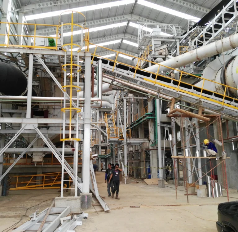
The electronic control system of the fertilizer production line focuses on large-scale, continuous production process control and needs to drive high-power equipment such as crushers (power can reach 100-200kW) and granulators (common power 200-500kW). Through the collaboration of PLC and DCS (distributed control system), it can achieve stable control of complex parameters such as raw material ratio, reaction temperature (precisely controlled at ±5℃), pressure (control accuracy ±0.1MPa), etc., to ensure the production of fertilizer products that meet the standards. The system reliability requirements are extremely high, and the mean time between failures (MTBF) usually needs to reach more than 10,000 hours. The fertilization and irrigation electronic control system is mainly used in farmland, greenhouse and other scenes. The control objects are mostly low-power equipment, such as solenoid valves (power about 10-50W), small water pumps (common power 1-5kW), etc. Sensors are used to collect data such as soil moisture and nutrient content. Remote monitoring and precise control are achieved through the Internet of Things technology. The water and fertilizer flow rate is accurately adjusted according to the growth needs of crops (control accuracy ±5%). The control range of a single irrigation and fertilization operation is generally from several acres to dozens of acres. The system emphasizes flexibility and intelligence.

Fertilizer production plant DCS control system: real-time monitoring, precise process automation, Enhance efficiency and reliability.
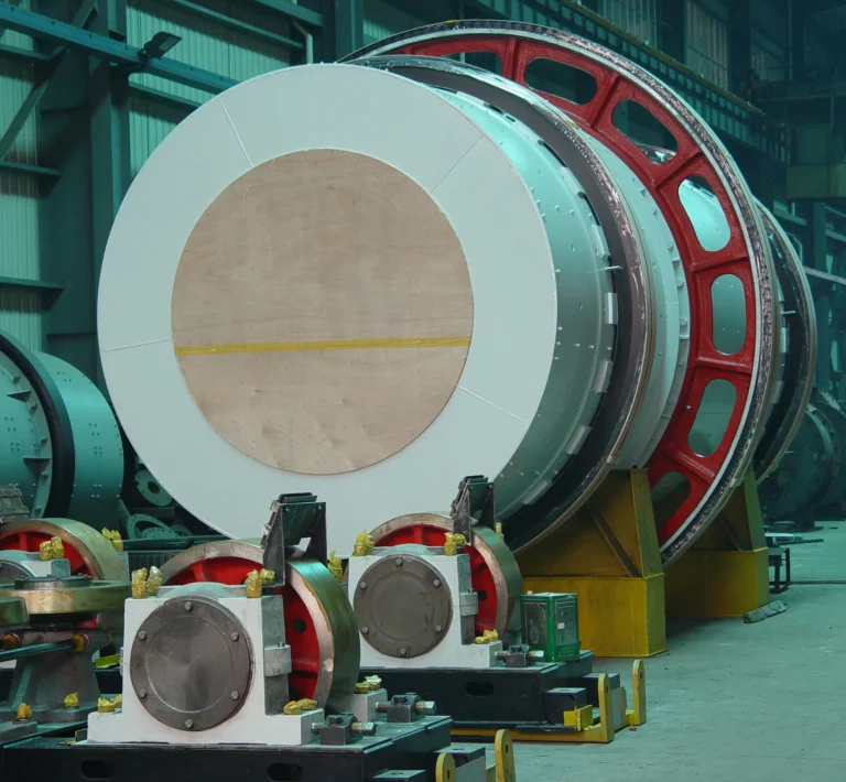
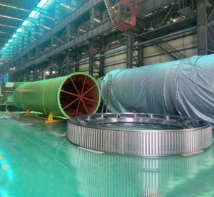
Tongli rotary drum dryer is adaptable to NPK compound organic fertilizer.

50/25kg automatic packing machine designed for fertilizer granule packaging only. Dedicated in handling npk compound fertilizer bagging.

Boost efficiency with our automated fertilizer palletizer – designed for fast, smooth packaging & stacking of 50/25kg fertilizer bags.

Adopts IP54 protection grade sealed cabinet, internal partition design (such as power area, control area separation). Equipped with Schneider NSX series circuit breaker, breaking capacity up to 100kA, bus system rated current up to 1600A, can withstand 50kA short-circuit current impact. The temperature-controlled fan automatically adjusts the temperature in the cabinet (set value: 35℃ start, 25℃ stop), ensuring that the components work in the best environment.

Integrated ABB ACS580 series inverter, supports vector control and direct torque control (DTC) technology, speed range 1:1000, speed control accuracy ±0.01%. Built-in EMC filter, in line with EN 61800-3 C2 class standard, effectively suppresses harmonic interference. The cooling system adopts forced air cooling, air volume 300m³/h, which can control the temperature rise in the cabinet within 15K.

Using Schneider ATS48 series soft starter, the starting current can be limited to 1.5-5 times the rated current (default 2.5 times) to achieve smooth motor starting. With phase control technology, it can reduce the torque impact when the motor starts (<1.3 times the rated torque). The bypass contactor closing time is <150ms, which reduces the operating energy consumption.

The shell is made of 304 stainless steel, with a wall thickness of 2mm and a protection level of IP66. Siemens S7-1200 PLC is installed inside, supporting PROFINET communication, and the number of I/O points is expanded to 128 points. The operating button adopts Schneider XB2 series, with a mechanical life of 1 million times and a protection level of IP67.

Ergonomic design, table top inclination angle of 30°, height adjustable range of 850-1050mm. Equipped with a 15-inch industrial touch screen (resolution 1024×768), supporting multi-touch. An isolation transformer (capacity 3kVA, ratio 1:1) is installed inside to effectively suppress common-mode interference. The bottom cable entry hole is sealed with fireproof mud, with a fireproof grade of FV-0.
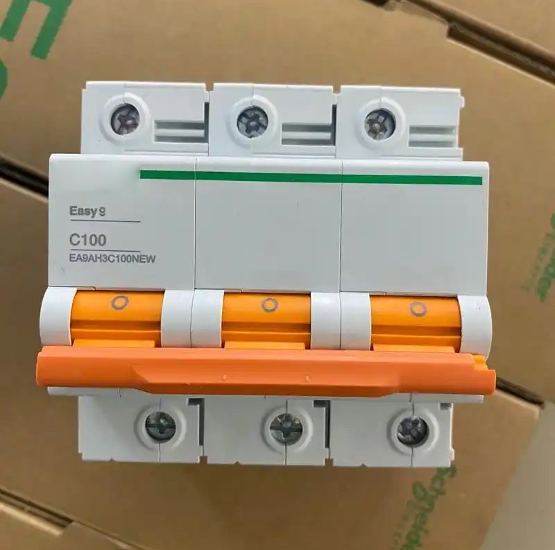
The circuit breaker uses Schneider Compact NSX series, with a breaking capacity of 50-150kA, equipped with Micrologic electronic release, which can achieve long delay overload (adjustable 1-10In) and short delay short circuit (adjustable 0.1-0.5s) protection. The contactor uses Schneider LC1-D series, with coil power consumption < 6VA and an electrical life of 10 million times.
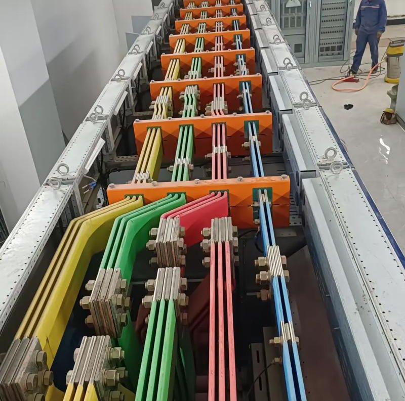
The busbar is made of T2 copper with a purity of ≥99.95%. The cross-sectional area is designed according to the current density of 2.25A/mm² (for example, a 100×5mm copper plate is used for a 400A circuit). The surface tin plating thickness is ≥8μm, and the contact resistance is <5μΩ. The bolt connection part adopts the tinning process, and the temperature rise is <60K (ambient temperature 40℃).

The PT100 platinum resistance sensor is used, with a measurement range of -50~200℃ and an accuracy of ±0.15℃. Protection level IP68, response time <5s. Output signal 4-20mA, linearity <0.05% FS. Installed in key parts such as circuit breaker contacts and busbar connections, the alarm is triggered when the temperature exceeds 70℃ (the alarm threshold can be set through the PLC program).
November 23, 2024

An In-Depth Exploration of High Tower Granulation Processes, Benefits, and Industry Applications
April 08, 2025
November 23, 2024
You can get in touch with us through the following contact information
AddressNo. 2289 Huancheng South Road, Tongxiang, Jiaxing, Zhejiang Province, China. Zip code:314500
Please fill in the sales inquiry form and our sales representatives will be in touch shortly.