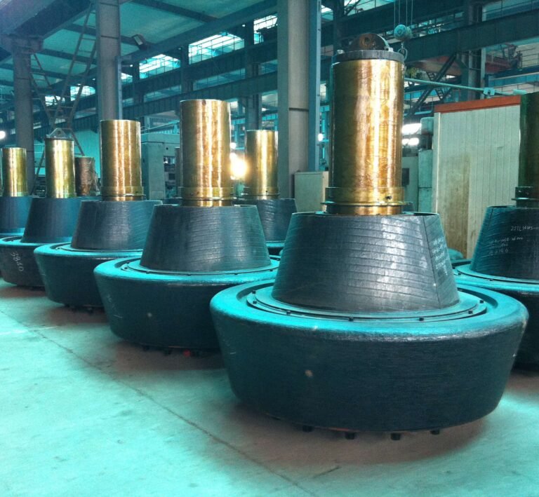


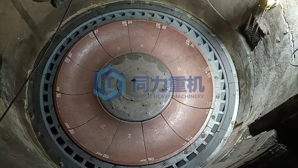
What is grinding table liner of a cement vertical roller mill?
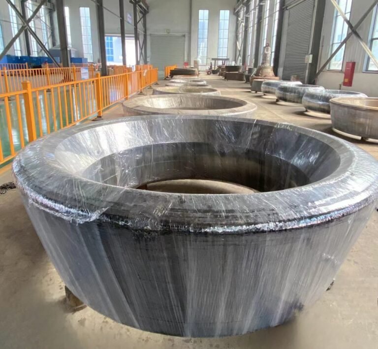
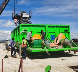
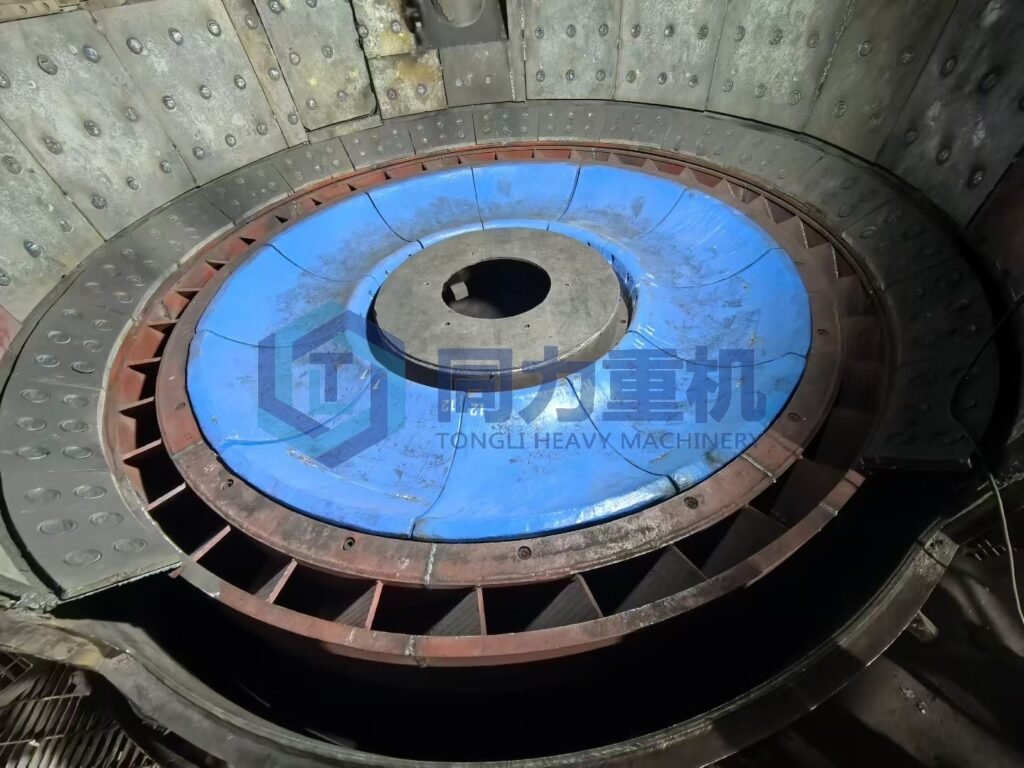
Like the picture shown above, the grinding table liner of a cement vertical roller mill is a critical wear-resistant component installed on the surface of the grinding table, where it directly interfaces with the grinding rollers and the material bed during comminution. Its primary function is to protect the table body from severe crushing, shearing, and abrasive wear from clinker and limestone while providing a stable and precisely contoured grinding surface. Structurally, table liners are manufactured with a high-strength cast steel base combined with a surfacing or embedded wear-resistant layer made from high-chromium cast iron or alloy materials, enabling them to withstand high contact stress, impact loads, and thermal cycling. The liners are designed in segmented sections to facilitate installation, alignment, and replacement, reducing maintenance downtime. By maintaining the correct grinding profile and surface roughness, the table liner directly influences grinding efficiency, vibration behavior, mill output, energy consumption, and the overall operational reliability of the cement vertical mill.
What is the structural design of a vertical milling machine table liner assembly?
The structure of a vertical roller mill grinding table liner typically includes a base plate and a wear-resistant layer, which are described in detail below, the grinding table liner has two structural shapes: flat disc and bowl-shaped. Both are segmented, and different shapes are suitable for different grinding processes and material properties.
Base Plate:
The veritcal roller mill grinding table liner base plate is the foundation of the grinding table liner, typically made of cast steel, such as ZG35SiMn. It provides support and a mounting base for the entire liner. During manufacturing, it undergoes casting, annealing, and machining processes to ensure dimensional accuracy and performance requirements.
Wear-resistant layer:
The wear-resistant layer is a crucial part of the grinding disc liner, directly contacting the material and withstanding grinding pressure and wear. Common wear-resistant layer structures include:
- Inlaying Carbide Blocks: Mounting holes are machined into the base plate, and carbide blocks are embedded within them. Carbide blocks are typically made of wear-resistant materials such as tungsten-based materials, like GD60A/GF50, which have high hardness and good wear resistance, effectively improving the service life of the liner. To increase the connection strength between the carbide blocks and the substrate, grooves can be machined on the side of the carbide blocks, and corresponding grooves are also machined into the inner surface of the mounting holes on the substrate. Fixing is achieved through copper brazing or bonding.
- Hardfacing Layer: A hardfacing layer is formed on the substrate, excluding the areas where carbide blocks are embedded, using a hardfacing method. The hardfacing layer material generally uses KSW series wear-resistant welding wire, etc. Circumferential hardfacing is performed using specialized rotating hardfacing welding equipment. The hardfacing thickness is typically controlled at 20-30mm. In the annular intervals between carbide blocks, manual hardfacing is also used for localized hardfacing, with a thickness controlled at 15-25mm.
- Integral Wear-Resistant Alloy Casting: Some grinding table liners are made from integral wear-resistant alloy casting. These liners offer uniform wear resistance and high overall strength, but are relatively expensive.
Connection Structure:
Wedge-shaped Connection:
Both the liner and the pressure block have a wedge-shaped structure. The wedge-shaped surfaces of the liner and the pressure block mate, and the liner's wedge-shaped surface has a locking slot, while the pressure block's wedge-shaped surface has a protrusion that mates with the locking slot. This locking method improves the stability of the grinding disc liner and prevents it from slipping out during grinding.
Bolt Connection:
The liner is fixed to the grinding disc with bolts. This connection method is common and relatively convenient for installation and disassembly. However, attention must be paid to the tightness of the bolts to ensure that the liner does not loosen during operation.
The grinding table liner has two structural shapes: flat disc and bowl-shaped
Flat disc vrm grinding table liner-Loesche vertical roller mills
Loesche vertical roller mills are traditionally characterized by a flat grinding table (flat disc) design. In this configuration, the grinding table surface is essentially planar, while multiple radially arranged rollers apply grinding pressure as they roll directly on the flat wear liners. Material is fed to the center of the table and is transported outward by centrifugal force, forming a stable grinding bed beneath the rollers. This flat-disc concept simplifies the mechanical structure of the table liner, allows for uniform wear distribution across the grinding surface, and makes liner replacement and maintenance relatively straightforward. The flat table design has become a defining feature of classic Loesche mills and has been widely adopted in raw material, coal, and cement grinding applications due to its proven operational stability and long service history.
Bowl-shaped vertical roller mill grinding table liner-Gebr. Pfeiffer MPS mills
Gebr. Pfeiffer MPS mills, by contrast, are distinguished by their curved or bowl-shaped grinding table (bowl-type grinding track). Instead of a flat surface, the table liner features a concave profile with a defined grinding track, which helps guide the material bed and stabilize it during grinding. The rollers are positioned to follow this curved surface, creating a grinding geometry that enhances material retention within the grinding zone and improves bed formation, particularly under varying feed conditions. This bowl-shaped design contributes to efficient grinding, reduced material spillage, and stable operation at high throughput levels. The curved grinding track is a hallmark of the MPS mill design and clearly differentiates Pfeiffer mills from flat-table VRM concepts in both liner geometry and grinding mechanics.
Why are grinding table liners designed in segmented sections?
Designing the vertical mill grinding table liner as a segmented structure is the mainstream solution in the field of industrial grinding equipment. Compared with integral liners, it has significant advantages in manufacturing, installation, maintenance, and operating costs.
Reduced Manufacturing Difficulty and Easier Quality Control:
Vertical roller mill grinding table typically have diameters of 2–6.2 metes for exmaple our ZJTL6240. Using a monolithic liner during casting easily leads to defects such as shrinkage cavities, cracks, and loose microstructure, and requires extremely large casting molds and processing equipment. A modular design allows the liner to be divided into several smaller pieces (commonly weighing 1–5t each), which not only adapts to small and medium-sized casting production lines but also ensures material uniformity through piece-by-piece flaw detection (such as UT ultrasonic testing), avoiding the risk of overall scrap.
Easy installation and replacement, reduced downtime.
Integral liners require large cranes (over 100 tons) for lifting and demand extremely high flatness of the grinding table mounting surface. Segmented liners can be lifted piece by piece using forklifts or small cranes, with single-piece replacement time controlled within 4–8 hours, while integral liner replacement typically requires 1–2 days. For continuous production in the cement production line raw milling and clinker grinding, the segmented design significantly reduces unplanned downtime and lowers production capacity losses.
Partial replacement after wear reduces maintenance costs
During vertical mill operation, the wear of the grinding disc liners is uneven: the wear rate in the material impact area (usually the center of the liner) is much higher than in the edge areas. Segmented liners allow for replacement of severely worn individual sections, eliminating the need for complete replacement and reducing spare parts costs by over 60%. For example, in a pulverized coal vertical mill equipped with a cement rotary kiln burner, typically only 2-3 worn sections in the center need replacement, while the edge liners can continue to be used for 1-2 cycles.
Adapting to the stress distribution of the grinding disc and extending service life
During operation, the grinding disc is subjected to compression, impact, and thermal stress. One-piece liners are prone to deformation or cracking due to stress concentration. The joints of segmented liners can serve as stress release channels, and the deformation of a single liner will not be transmitted to other areas, effectively preventing cascading damage. This is especially suitable for grinding high-hardness materials (such as cement clinker and phosphate rock).
What groove patterns are used on VRM grinding table liners and why?
The purpose of the groove design of the grinding table liner of the vertical roller mill (VRM) is to optimize material conveying, enhance grinding efficiency, reduce energy consumption, and extend the liner life. Different groove designs are adapted to different grinding conditions and material characteristics.
Radial Straight Grooves
Grooves are linearly distributed along the radius of the grinding disc, radiating outwards from the center. The width and depth of the grooves gradually change from the inside out (typically narrower and deeper at the inside and shallower at the outside).
- Fast Material Flow:** The rotating grinding disc, through the radial grooves, rapidly transports material from the central drop zone to the grinding roller pressing zone, preventing material accumulation in the center. Suitable for materials with good flowability (such as cement raw materials and pulverized coal).
- Reduced Material Slippage Loss: The straight groove structure reduces lateral slippage of material during transport, ensuring more material enters the grinding roller pressing zone and participates in grinding, improving grinding efficiency.
- Easy to Process and Maintain: The regular groove shape makes casting and machining easier. The continuity of the grooves is easily ensured after splicing with segmented liners, and repair costs are low after wear.
Herringbone Grooves
Grooves are arranged in a staggered "V" shape, originating from the center of the grinding disc. Adjacent grooves have opposite inclination directions, and the groove depth and width are uniform or gradually varying.
- Enhanced Material Aggregation: The inclination angle of the herringbone grooves guides material towards the roller pressing zone in the center of the grinding disc, preventing excessive outward spillage. This is particularly suitable for materials with poor flowability and agglomeration (such as slag, phosphate rock, and chemical waste).
- Improved Grinding Uniformity: Material experiences bidirectional compression and shearing within the herringbone grooves. Compared to radial straight grooves, this results in more thorough particle breaking and reduced coarse powder return.
- Dispersed Liner Wear Zones: The staggered grooves ensure more uniform pressure distribution on the grinding rollers, preventing localized groove failure due to excessive wear and extending the overall service life of the liner.
Spiral Grooves
Grooves are distributed in a spiral pattern along the circumference of the grinding disc. The spiral direction is the same as or opposite to the rotation direction of the grinding disc, and the groove depth gradually decreases from the inside to the outside.
- To achieve "gradient grinding" of materials: The lead design of the spiral grooves controls the residence time of materials on the grinding disc. The inner deep grooves are used for coarse crushing, and the outer shallow grooves are used for fine grinding, suitable for applications requiring ultrafine grinding (such as ultrafine cement and chemical fillers).
- Reduced airflow loss within the mill: The streamlined structure of the spiral grooves reduces airflow resistance on the grinding disc surface, improving the fineness of the finished product when used with a classifier, while reducing system fan energy consumption.
- Excellent impact resistance: The arc transition of the spiral grooves buffers the impact of large pieces of material on the liner, preventing chipping at the groove edges, suitable for applications with large fluctuations in feed particle size.
Flat Liner
The liner surface has no obvious grooves, presenting a flat or slightly curved surface. Some liner surfaces may have wear-resistant protrusions. Suitable for ultra-fine grinding or applications where materials are prone to over-grinding (e.g., fine processing of fly ash). The flat surface reduces material retention in grooves, preventing increased energy consumption due to over-grinding. Simplifies liner structure, reduces the risk of casting defects, and is suitable for small-diameter grinding discs or experimental vertical mills.
Which VRM grinding table groove patterns you should choose?
Material Characteristics Priority: Herringbone grooves are preferred for materials prone to agglomeration and with high hardness; radial straight grooves are preferred for materials with good flowability and requiring rapid conveying; spiral grooves are preferred for ultrafine grinding.
Matching Grinding Process: For closed-circuit grinding systems (with classifiers), spiral or herringbone grooves can be used to improve grinding uniformity; for open-circuit grinding systems, radial straight grooves can be used to simplify the structure.
Considering Operation and Maintenance Costs: The continuity of grooves in segmented liners needs to be carefully considered. Radial straight grooves have the lowest splicing difficulty, while herringbone and spiral grooves require strict control of the groove alignment tolerance of individual liner pieces (≤±0.5mm).
What materials are commonly used for VRM grinding table liners?
The liner material must be matched to the characteristics of the ground material and the operating conditions; otherwise, even with high installation precision, its service life cannot be guaranteed. In the chemical and fertilizer industries, for grinding highly abrasive materials such as pulverized coal and phosphate rock, but with low impact loads, high-chromium cast iron (Cr15–26) is typically selected. Its hardness can reach HRC58–62, offering excellent wear resistance. In clinker grinding in the cement industry, the liner needs to withstand both high abrasion and cyclic impact loads, often using nickel-hard cast iron (Ni-Hard 4). This material maintains good wear resistance while possessing higher fracture toughness, effectively reducing the risk of liner chipping and breakage. For ultrafine grinding or extreme wear conditions, tungsten carbide alloy overlay or composite wear-resistant layer treatment can be applied to the working surface of the liner. Its service life can typically be extended by 2–3 times compared to ordinary cast iron liners, but the matching of the grinding roller material must be considered simultaneously.
What is the composition of a vertical roller mill grinding table liner?
So here we would list 4 mainstream grinding table liner material: 1. Steel Casting with Surface Welding (Composite Hardfaced Liner); 2. High-Chromium Cast Iron Grinding Table Liner 3. Ceramic Composite Grinding Table Liner;
1. Steel Casting with Surface Welding (Composite Hardfaced Liner)
This structure closely resembles Magotteaux NeoX®-type liners, where wear life is maximized through renewable or thick hardfaced layers while maintaining excellent resistance to impact and vibration.
| Component | Typical Composition (wt.%) | Function |
| Base material (cast steel) | C 0.25–0.45 Mn 0.6–1.5 Si 0.3–0.8 Cr ≤1.5 Mo ≤0.5 | Provides high toughness, impact resistance, and structural strength |
| Hardfacing layer | C 3.0–5.5 Cr 18–30 Mo 0–3 Nb / V 0–5 (optional) | Forms dense chromium carbides or complex carbides for abrasion resistance |
| Matrix structure | Martensitic + carbide network | Balances wear resistance and crack resistance |
| Typical hardness | Base: HB 200–280 Surface: HRC 55–65 | Wear-resistant working layer with tough substrate |
2. High-Chromium Cast Iron Grinding Table Liner
High-Cr cast iron liners provide excellent cost-to-wear performance but are more sensitive to impact loading and thermal shock than composite steel-based designs.
| Element | Typical Composition (wt.%) | Role |
| Carbon (C) | 2.2–3.2 | Promotes carbide formation |
| Chromium (Cr) | 15–28 | Forms M₇C₃ chromium carbides for abrasion resistance |
| Silicon (Si) | 0.5–1.5 | Improves castability and matrix stability |
| Manganese (Mn) | ≤1.5 | Strengthens matrix and improves toughness |
| Molybdenum (Mo) | 0–3 | Refines carbides and improves high-temperature performance |
| Nickel (Ni) | ≤2 | Enhances toughness and thermal stability |
| Typical hardness | HRC 58–62 | High wear resistance under abrasive conditions |
3. Ceramic Composite Grinding Table Liner
Ceramic grinding table liners offer the longest wear life in highly abrasive, low-impact applications but require stable operating conditions and precise installation to prevent ceramic fracture.
| Component | Typical Composition | Function |
| Metal backing | Steel or low-alloy iron C 0.3–1.0 Cr 1–5 | Structural support and impact absorption |
| Ceramic phase | Al₂O₃ ≥90% or ZrO₂ / SiC (application-dependent) | Extreme abrasion resistance |
| Bonding method | Mechanical interlocking or metallurgical bonding | Ensures load transfer between ceramic and metal |
| Hardness | Ceramic: HV 1200–1800 Composite surface > HRC 70 | Ultra-high wear resistance |
What is the difference between cast steel and high-chromium table liners?
cast steel liners offer greater structural safety and flexibility, especially during start-up, shutdown, and process upsets, but usually require hardfacing or more frequent maintenance to achieve long wear life. High-chromium liners deliver longer wear life in steady, abrasive grinding, but demand stricter process control and careful installation to avoid premature failure. In practice, the choice between the two depends on whether the application prioritizes impact resistance and reliability (cast steel) or abrasion resistance and wear life (high-chromium cast iron).
Cast steel liners
Cast steel table liners are designed to prioritize toughness and impact resistance. With relatively low carbon content and a steel-based matrix, cast steel liners can absorb repeated cyclic loads from the grinding rollers without cracking. This makes them particularly suitable for large VRMs, high grinding pressures, and operating conditions where impact loads, vibration, or foreign materials are present. Cast steel liners typically wear through plastic deformation and gradual surface abrasion rather than brittle fracture, and they are often combined with surface hardfacing layers to improve wear life while retaining a tough core.
- The base material is medium-carbon or low-carbon alloy cast steel (such as ZG35CrMo, ZG42CrNi), with a carbon content typically between 0.2% and 0.6%, and alloying elements (Cr, Ni, Mo) accounting for ≤5%.
- The microstructure is mainly pearlite and ferrite, with some areas forming tempered sorbite after heat treatment. The matrix exhibits excellent toughness, but has a low content of hard phases (mainly cementite).
Applications of Cast Steel Liners, When should I use it?
- Suitable for applications with large feed particle size and high impact loads, such as: crushing large ores (particle size > 100mm) in vertical mills, and grinding high-hardness materials that are prone to impact (such as basalt).
- Adapted to low-speed, heavy-duty vertical mill models, or areas easily impacted by materials, such as the edges of the grinding disc. Its high toughness prevents the liner from chipping or breaking due to impact.
- Suitable for cost-sensitive applications with slow wear rates, such as grinding low-hardness materials like fly ash and coal gangue.
High-chromium vertical roller grinding table liners
High-chromium table liners, by contrast, are engineered for maximum abrasion resistance. Their high carbon and chromium content leads to the formation of hard chromium carbides within the microstructure, resulting in significantly higher surface hardness than cast steel. This makes high-chromium liners highly effective when grinding abrasive materials such as slag, raw meal, or mineral additives under relatively stable conditions. However, the same hard, carbide-rich structure also makes them more brittle, meaning they are less tolerant of impact loads, sudden pressure fluctuations, or tramp metal, which can cause edge chipping or cracking.
- The base material is high-chromium white cast iron (Cr15–Cr26), with a carbon content of 2.0%–3.5% and a chromium content of ≥15%, with some additions of alloying elements such as Mo and Cu to enhance performance.
- The microstructure consists of a martensitic matrix + M₇C₃ type high-hardness carbides, with the hard phase distributed in a network or discontinuous pattern. The hardness can reach HRC60–65, and the matrix hardness can also reach HRC40–45.
Applications of High-chromium cast iron grinding table liner, When should I use it?
- Suitable for applications where abrasive wear is the primary factor and impact loads are low, such as grinding phosphate rock, coal, and cement raw materials in the chemical and fertilizer industries, and grinding clinker in the building materials industry.
- Adaptable to medium- and high-speed vertical mills for fine grinding, especially suitable for the central grinding zone of segmented liners (where materials are ground by rollers, resulting in low impact and concentrated wear).
- Suitable for continuous production lines with high downtime costs; its long service life reduces replacement frequency and minimizes unplanned downtime.
High-chromium vs Cast steel vertical roller mill liner which one I should choose?
For impact applications, cast steel is preferred; for wear applications, high-chromium cast iron is preferred. If the feed particle size fluctuates greatly and large pieces of material frequently appear, cast steel is the preferred choice. If the grinding of materials is mainly characterized by roller pressure wear, high-chromium cast iron is the preferred choice.
Segmented liners can be used in combination: cast steel liners are used at the edges of the grinding disc (affected by impact), while high-chromium cast iron liners are used in the central grinding zone (affected by wear), balancing cost and lifespan.
Heat treatment processes affect performance: cast steel liners require quenching and tempering to improve strength and toughness; high-chromium cast iron liners require quenching and tempering to ensure uniform carbide distribution and avoid excessive brittleness.
Which grinding table liner material is best for cement, slag, or coal?
Selecting the optimal grinding table liner material for a vertical roller mill is a materials-engineering decision, not a marketing one. Cement clinker, slag, and coal impose very different combinations of abrasion, impact, temperature, and chemical attack, and the “best” liner is the one whose wear mechanism matches the dominant failure mode of the application.
Cement clinker grinding – We Recommand Cast steel with hardfacing (composite liner)
Best choice for cement clinker ➡️ Cast steel base + high-carbide hardfacing layer
Cement clinker grinding subjects the table liner to high compressive stress, strong cyclic impact, and moderate-to-high abrasion. Clinker particles are hard but angular, and the grinding bed is repeatedly loaded and unloaded as rollers pass, creating severe subsurface stress. In this environment, fracture resistance and fatigue strength are more critical than extreme surface hardness. For this reason, cast steel table liners with a hardfaced working surface are technically the most suitable solution. The steel substrate (typically low-alloy cast steel) absorbs impact energy and resists crack propagation, while the hardfacing layer—rich in chromium carbides or complex carbides—provides adequate abrasion resistance. This composite structure allows controlled wear by surface abrasion rather than brittle chipping, which is why it is widely used in large cement VRMs and solutions comparable to NeoX®-type liners. Monolithic high-chromium cast iron liners, although harder, are more prone to edge breakage and thermal cracking in clinker service.
Slag grinding – We Recommand High-chromium cast iron or advanced composite liners
Best choice for slag:➡️ High-chromium cast iron or steel-backed composite / ceramic-reinforced liners for high-duty VRMs
Granulated blast furnace slag is extremely abrasive, often harder than clinker due to its glassy structure and high silica content. Impact loads are generally lower than in clinker grinding, but abrasive wear dominates, especially at the grinding track and outer table zones. In this case, surface hardness and carbide volume fraction are the primary performance drivers.
High-chromium cast iron table liners (15–28% Cr) perform very well in slag grinding because the dense M₇C₃ carbide network provides excellent resistance to micro-cutting and scratching. When operating conditions are stable and tramp metal risk is low, high-Cr liners deliver long, predictable wear life. For very large mills or high-throughput slag grinding, steel-backed composite liners with thick hardfacing or ceramic-reinforced zones are increasingly used to combine abrasion resistance with structural safety.
Coal grinding – We recommand High-chromium cast iron (with thermal stability focus)
Best choice for coal:➡️ High-chromium cast iron
Coal grinding imposes a different wear regime: abrasion levels are relatively low, impact forces are modest, but thermal stability, oxidation resistance, and erosion from fine particles become important. In addition, coal mills must tolerate temperature fluctuations and, in some cases, chemical attack from sulfur compounds. High-chromium cast iron liners are well suited for coal grinding because they provide sufficient wear resistance without requiring extreme toughness. Their carbide-rich structure resists erosive wear from fine coal particles, and their performance remains stable at typical coal mill operating temperatures. Cast steel liners are generally unnecessary unless the mill experiences abnormal impacts or foreign material ingress, in which case toughness may become a concern.
How does grinding table liner profile affect grinding efficiency?
The profile of a vertical roller mill (VRM) grinding table liner directly controls material bed formation, load transfer, particle movement, and energy utilization under the rollers. Even with the same liner material, an inappropriate profile can significantly reduce throughput and increase power consumption, therefore we need to take it serious!
First, the overall table geometry—flat versus bowl-shaped—determines how effectively the grinding bed is stabilized. A flat table profile relies mainly on centrifugal force and groove geometry to spread material outward. When properly designed, it allows uniform pressure distribution and predictable wear, but it is more sensitive to feed fluctuations. A bowl-shaped profile, by contrast, naturally confines the material within a defined grinding track, increasing bed stability and reducing material slippage. A stable grinding bed improves the transmission of roller pressure into particle breakage rather than bed displacement, thereby increasing specific grinding efficiency.
Second, the liner surface contour and groove depth influence material residence time and breakage probability. A profile with insufficient relief or worn-down grooves allows material to escape the grinding zone too quickly, resulting in under-ground particles and higher circulating load. Conversely, a well-profiled liner with properly sized grooves promotes repeated compression and shear of particles, increasing the number of effective breakage events per unit of energy input. Excessively deep or aggressive profiles, however, can trap material, increase internal friction, and raise power consumption without proportional size reduction.
Third, the interaction between liner profile and roller shape affects contact mechanics and stress distribution. A liner profile that matches the roller curvature creates a uniform contact zone and consistent pressure field across the grinding bed. If the profile is mismatched—such as uneven liner height or distorted grinding tracks—roller load becomes non-uniform, leading to localized overgrinding, vibration, and accelerated wear. Efficient grinding depends on converting roller force into controlled compressive and shear stresses, which is only possible when the liner profile is geometrically consistent.
Finally, the evolution of the liner profile over time has a strong impact on sustained efficiency. As the profile wears and grooves become shallow, the grinding bed becomes less stable and material flow accelerates, reducing grinding intensity. This is why many high-efficiency VRMs use re-profilable liners, hardfaced surfaces, or profile-optimized designs that maintain their functional geometry throughout the wear life. In practical terms, maintaining an effective liner profile can improve throughput, reduce specific power consumption, and extend liner and roller service life simultaneously.
- Matching material characteristics: For high-hardness, large-particle-size materials, choose deep grooves with steep slopes; for low-hardness, ultrafine grinding, choose shallow grooves with gentle slopes.
- Balancing capacity and fineness: For higher capacity, choose radial straight grooves; for higher fineness, choose herringbone or spiral grooves.
- Dynamic adjustment: As the liner wears, the groove depth and slope will change. Regular inspection is necessary. Replace the liner promptly when the groove depth wear exceeds 50% to avoid a significant decrease in grinding efficiency.
Trench depth and slope: determine bed thickness and material conveying efficiency
Deep Grooves + Steep Slope
- Mechanism of Action: Deep grooves can store more material, while a steep slope (groove sidewall inclination angle > 45°) utilizes the centrifugal force of the rotating grinding disc to quickly transport material from the center of the disc to the roller pressing zone.
- Efficiency Impact: Suitable for large feed particle sizes and high-capacity applications (such as cement clinker and slag grinding). It avoids material accumulation in the center, ensuring a stable material bed thickness of 20–50 mm in the roller pressing zone, thus increasing the crushing ratio per roller pressing.
- Precautions: Grooves that are too deep (> 80 mm) can cause excessive material accumulation in the groove, with some material being thrown out before entering the roller pressing zone, reducing grinding efficiency. A slope that is too steep (> 60°) will accelerate material ejection, increasing the amount of recycled material.
Shallow Grooves + Gentle Slope
- Mechanism of Action: Shallow grooves (depth 10–30 mm) combined with a gentle slope (inclination angle 20–35°) can extend the residence time of material in the roller pressing zone, enhancing the fine grinding effect.
- Efficiency Impact: Suitable for ultrafine grinding applications (such as fine processing of fly ash and grinding of chemical fillers), allowing materials to pass through the roller pressing zone multiple times, reducing the coarse powder content of the finished product and improving the efficiency of the classifier.
- Precautions: Shallow grooves are not suitable for large-diameter materials, as they can easily lead to "excessively thin material bed" causing direct contact between the roller surfaces, resulting in vibration and accelerated wear of the liner.
Groove shape: affects the stress state of the material and the uniformity of grinding
Radial Straight Groove Type
- Force Characteristics: Material moves along a straight trajectory, subjected to unidirectional extrusion force, resulting in low motion resistance.
- Efficiency Impact: High material conveying speed, suitable for materials with good flowability (such as pulverized coal and cement raw materials), increasing mill throughput; however, the material's grinding time is short, and the uniformity of finished product fineness is generally average.
- Applicable Scenarios: Open-circuit grinding systems seeking high production capacity.
Herringbone Groove Type
- Force Characteristics: Material is subjected to bidirectional extrusion and shear forces within the staggered grooves, resulting in an "S"-shaped motion trajectory and extended residence time.
- Efficiency Impact: Significantly improved grinding uniformity, reducing coarse powder content by 10%–15%, suitable for materials prone to agglomeration and with poor flowability (such as slag and wet pulverized coal), reducing over-grinding and lowering unit energy consumption.
- Applicable Scenarios: Closed-circuit grinding systems requiring high finished product fineness.
Spiral Groove Type
- Force Characteristics: Material moves along a spiral gradient, with deep inner grooves for coarse grinding and shallow outer grooves for fine grinding, achieving "staged grinding."
- Efficiency impact: Lowest unit energy consumption (8%–12% lower than radial straight groove), small fluctuation in finished product fineness, suitable for fine grinding conditions, but groove processing is difficult and the liner manufacturing cost is high.
Liner surface roughness: affects bed stability and sliding loss
Rough Surface (Surface Roughness Ra 12.5–25 μm)
- Mechanism of Action: The uneven surface structure increases the friction between the material and the liner, preventing material slippage in the roller pressing zone and forming a stable material bed.
- Efficiency Impact: Improved material bed stability, reduced mill vibration, and increased grinding efficiency by 5%–8%. Suitable for low-hardness, easily slipping materials (such as coal and fly ash).
Smooth Surface (Surface Roughness Ra 3.2–6.3 μm)
- Mechanism of Action: Low surface friction coefficient, good material slippage, and less adhesion to the liner surface.
- Efficiency Impact: Suitable for high-hardness, easily adhering materials (such as cement clinker and slag). It avoids uneven material bed thickness caused by material sticking to the trough and reduces localized wear on the liner.
How does table liner material selection affect mill power consumption?
The selection of grinding disc liners directly affects the unit product power consumption and system operating power of the vertical roller mill through three core dimensions: wear resistance, coefficient of friction, and mechanical compatibility.
Wear-resistant materials reduce ineffective frictional losses
Low wear-resistant materials increase power waste. Ordinary cast steel, ductile iron and other low wear-resistant materials wear quickly, and the working surface is prone to "polishing" phenomenon. The friction coefficient drops sharply, and the material cannot form an effective material bed in the roller pressing area, resulting in the phenomenon of "empty rolling. The grinding roller is in direct contact with the liner, which not only increases equipment vibration, but also causes a lot of power to be consumed by friction between metals instead of material breakage.
Liners made of wear-resistant materials such as high-chromium cast iron and nickel-hard cast iron have a working surface hardness of HRC58~65. Their microstructure contains high-hardness M₇C₃ type carbides, making their resistance to abrasive wear 3~5 times that of cast steel.
In the new liner stage: The working surface roughness of the wear-resistant material is stable, the friction coefficient between the material bed and the liner is controllable, the material crushing efficiency is high, and the unit product power consumption is 8%~12% lower than that of cast steel liners (taking cement clinker grinding as an example).
In the later stages of wear: The groove profile of the wear-resistant material decays slowly, maintaining a stable material bed thickness (20~50mm), avoiding material slippage and material bed instability caused by groove flattening, and controlling power fluctuation within ±3%; while in the later stages of wear, the grooves of cast steel liners fail, material slippage loss increases, power fluctuation can reach ±10% or more, and power consumption increases by 15%~20%.
The effect of friction coefficient on bed stability and power regulation
The coefficient of friction of the liner material determines the motion of the material on the grinding disc, which in turn affects the stability of the material bed and is ultimately reflected in power consumption.
High-friction coefficient material:
Strengthens the material bed and reduces power fluctuations. High-chromium cast iron (surface roughness Ra 12.5~25μm) has a friction coefficient of 0.35~0.45, effectively preventing material slippage under centrifugal force and quickly forming a dense and stable material bed. A stable material bed ensures uniform force on the grinding rollers, avoiding "rigid impact" caused by an excessively thin material bed, resulting in smaller system power fluctuations and a 5%~8% reduction in average power consumption. This characteristic is particularly suitable for materials with poor flowability (such as slag and wet coal powder), reducing frequent start-ups and power waste caused by material bed collapse.
Low-friction coefficient material:
Prevents adhesion and reduces unnecessary power consumption. Liners with surface hardening or tungsten carbide overlay have a friction coefficient as low as 0.2~0.25, with a smooth surface that does not easily adhere to materials, making them suitable for high-hardness, easily sticking materials (such as cement clinker). This type of material can prevent materials from "sticking and clumping" in the groove, prevent additional power consumption caused by the breakage of clumped materials, and reduce uneven material bed thickness caused by adhesion, making the mill's operating power more stable.
The indirect impact of material mechanical compatibility on system power
The toughness, impact resistance, and other mechanical properties of the lining material indirectly affect power consumption through the stability of equipment operation. Under conditions of large fluctuations in feed particle size and the presence of large pieces of material, the high toughness of cast steel liners (ZG35CrMo) can withstand material impact and prevent liner chipping and cracking. If high-chromium cast iron with high brittleness is selected, impact loads will cause localized damage to the liner, resulting in uneven stress on the grinding rollers and increased mill vibration (exceeding 8 mm/s). To maintain stable operation, the system needs to increase power, increasing power consumption by 10% to 15%. For efficient crushing, the liner hardness must be 1.5 to 2 times higher than the material hardness. For grinding coal (Mohs hardness 1-2): medium chromium cast iron (HRC55-58) is sufficient to meet wear resistance requirements; excessively high hardness is unnecessary, as it increases liner manufacturing costs and leads to over-grinding of materials, increasing unnecessary power consumption.
| Table Liner Material | Typical Specific Power Consumption* (kWh/t) | Power Fluctuation Range | Wear Mechanism & Profile Stability | Grinding Bed Behavior | Technical Assessment |
| Ni-Hard Cast Iron (Ni-Hard 4) | 28–32 | ±2% to ±3% | Martensitic matrix + carbides provides excellent abrasion resistance with moderate impact tolerance; liner profile retention is very high | Stable, dense grinding bed with minimal slip and vibration | Lowest and most stable power consumption; optimal balance of hardness and toughness for cement clinker |
| High-Chromium Cast Iron (Cr18–22 / Cr20) | 30–34 | ±3% to ±4% | High volume of M₇C₃ carbides gives superior abrasion resistance but lower impact tolerance; profile stability is high under steady feed | Stable grinding bed under uniform feed conditions | Very efficient under stable operating conditions; slightly higher power draw due to increased brittleness and micro-chipping risk |
| Alloy Cast Steel (ZG35CrMo / ZG42CrNi) | 35–40 | ±8% to ±10% | Tough matrix resists impact but wears plastically; groove geometry degrades quickly | Grinding bed less stable; higher slip and vibration tendency | Higher power consumption due to rapid profile loss and increased friction losses |
| Ordinary Ductile Iron (QT500–7, etc.) | 42–48 | ±10% to ±15% | Low hardness leads to severe abrasive wear; liner profile deteriorates rapidly | Poor grinding bed stability, frequent material collapse | Highest power consumption and instability; suitable only for low-duty or short-life applications |
How does the grinding table liner affect cement fineness and quality?
Cement fineness, Blaine specific surface area, particle size distribution, compressive strength, and water demand ratio are directly impacted by the grinding liner type. optimized liner structures can increase specific surface area by 10–15% and reduce 80 μm sieve residue by 30–40%, while high-performance wear-resistant materials can reduce liner wear rates by more than 50%, ensuring long-term cement quality stability. Therefore, in engineering practice, liner selection must be scientifically optimized based on cement type, material characteristics, and mill operating parameters, and liner wear thresholds must be strictly controlled.
Influence of Liner Structure on Cement Fineness and Specific Surface Area
TONGLI Vertical roller mill comparative tests:
To investigate the influence of liner thickness on grinding performance, high-chromium cast iron liners with thicknesses of 3 mm, 5 mm, and 7 mm were tested under standardized conditions of 14 g centrifugal acceleration and 5 min grinding time. The results showed that the 3 mm liner achieved a finished powder yield of 66.62%, with 45 μm sieve residue of only 8.2% and a Blaine specific surface area of 3850 cm²/g. In contrast, with the 7 mm liner, the 45 μm residue increased to 15.6% and the specific surface area decreased to 3200 cm²/g. This is attributed to the higher energy transfer efficiency of thinner liners and a more reasonable material residence time in the grinding zone, which significantly increases the generation of fine particles.
Integra Cement Φ4.0 m tongli vertical roller mill (VRM) industrial comparative tests:
During the production of P·O 42.5 cement with 30% slag addition, a comparison was conducted between conventional stepped liners and corrugated–grooved composite liners. The data showed that the composite liner system achieved an hourly throughput of 135 t/h, representing a 12.4% increase compared with stepped liners (120 t/h). The 80 μm sieve residue decreased from 8.5% to 5.2%, while the specific surface area increased from 3500 cm²/g to 3900 cm²/g. Meanwhile, the wear rate of the composite liner was 2.1 times lower than that of the stepped liner, with significantly improved grinding stability. The 3-day compressive strength of the finished cement increased by 4.2 MPa, and the 28-day compressive strength increased by 3.5 MPa.
MAGOTTEAUX liner industrial retrofit trial:
After a cement plant replaced its original 55 mm thick liners with 35 mm thick new-type corrugated liners, the 45 μm residue at the mill outlet decreased from 12.8% to 7.5%, and the specific surface area increased from 3300 cm²/g to 3750 cm²/g. The overall system power consumption was reduced by 2 kWh/t, the mill motor current decreased by 20 A, and after 10 months of operation, the liners exhibited virtually no noticeable wear. This effectively ensured long-term stability of cement fineness.
Quantitative Influence of Liner Material and Wear Condition on Cement Quality
Simulated tests by the Tribology Laboratory of TONGLI:
Under VRM cement mill operating conditions with impact energy ≤ 5 J and sliding velocity of 1.2 m/s, the wear behavior and cement quality effects of high-chromium cast iron liners and high-toughness alloy steel liners were compared. The results indicated that after 1000 h of operation, the high-chromium cast iron liner exhibited a surface wear depth of 12 mm, with obvious reduction in groove depth. This led to an increase in the proportion of particles larger than 80 μm in the finished cement to 10.3%, and the water demand ratio increased by 1.8%. Under the same conditions, the high-toughness alloy steel liner showed a wear depth of only 5 mm, with the coarse particle fraction remaining below 6.5%, and a stable water demand ratio. This is attributed to the superior anti-spalling and anti-chipping resistance of alloy steel liners, which prevents grinding efficiency deterioration and cement property fluctuations caused by liner material spalling.
Industrial validation data for liner wear threshold:
A cement plant conducted long-term monitoring of the grinding table liners of a Φ3.8 m vertical cement mill. When the groove depth was worn to 50% of the original design value, the 80 μm sieve residue of the finished cement increased from 4.8% to 9.2%, and the specific surface area decreased from 3800 cm²/g to 3400 cm²/g. At the same time, the 3-day compressive strength decreased by 3.6 MPa, and the 28-day compressive strength decreased by 2.8 MPa. When the wear exceeded 70% of the design threshold, the mill vibration level increased to 5.2 mm/s, forcing operators to reduce grinding pressure. This further deteriorated cement fineness, with quality fluctuations expanding to ±2.5 MPa.
Influence of Liner Surface Topography on Cement Particle Size Distribution and Hydration Activity
Particle morphology analysis conducted by TONGLI showed that cement ground with chevron-pattern (herringbone) liners achieved a particle sphericity of 0.82, whereas cement ground with worn, smooth liners exhibited a sphericity of only 0.68. Higher particle sphericity increased cement flowability by 8%, accelerated hydration kinetics, and improved 3-day compressive strength by 3.1 MPa. Conversely, an increased proportion of angular particles resulted in higher water demand, reduced concrete workability, and negatively affected the development of later-age strength.
How does the grinding table liner influence material bed formation?
The three key elements of material bed formation are: the liner controls the material bed through three stages: "groove constraint → friction gripping → thickness control". The groove structure determines the material movement trajectory, the friction coefficient determines the material residence time, and the wear state determines the parameter decay rate. The three factors together affect the material bed's "thickness, uniformity, and density".
Liner groove angle and depth affects material bed formation on vertical roller mill grinding table:
The experiment was conducted in a Tongli Φ1200mm vertical mill simulation, with the grinding pressure controlled at 120kN and the grinding disc speed at 18r/min. The effects of the groove angle (15°/22°/30°) and depth (15mm/25mm/35mm) of the herringbone liner on the material bed were compared. The data are shown in the table below:
| Groove Geometry | Material Bed Thickness (mm) | Thickness Fluctuation (±mm) | Material Bed Bulk Density (g/cm³) | Mill Vibration Level (mm/s) | 45 μm Sieve Residue (%) |
| 15°/15 mm | 42 | 5.8 | 1.42 | 4.8 | 14.5 |
| 22°/25 mm | 65 | 2.1 | 1.68 | 2.3 | 8.2 |
| 30°/35 mm | 78 | 4.2 | 1.55 | 3.5 | 10.8 |
The combination of a 22° groove angle and a 25mm depth keeps the bed thickness stable within the design range (60-70mm), achieves peak density, and minimizes vibration. This is because the parameters match the balance between the centrifugal force of the material and the pressure of the grinding roller, preventing material from "overflowing" or "accumulating".
Φ4.0m grinding table diameter vertical roller mill industrial experiment (comparison of liner structure)
| Liner Type | Average Material Bed Thickness (mm) | Edge–Center Thickness Difference (mm) | Stable Operating Period (h) | Hourly Throughput (t/h) | Specific System Power Consumption (kWh/t) |
| Stepped Liner | 58 | 18 | 4500 | 120 | 31.2 |
| Composite Liner | 62 | 8 | 7200 | 135 | 28.8 |
The composite liner, through the synergistic effect of "guiding and retaining" in the grooves, reduces the thickness difference of the material bed by 55%, extends the stabilization cycle by 60%, and significantly improves the uniformity of the material bed, directly leading to an increase of 12.5% in hourly output and a decrease of 7.7% in power consumption.
MAGOTTEAUX Liner Depth Wear Tracking Experiment
A cement plant monitored the wear process of a Φ3.8m grinding disc diameter vertical roller mill as the groove depth decreased from 35mm to 10mm. The data are as follows:
| Remaining Groove Depth | Material Bed Thickness (mm) | Thickness Fluctuation (±mm) | Grinding Roller Pressure Decay Rate (%) | 3-Day Strength Reduction (MPa) |
| 100% (35 mm) | 68 | 2.5 | 0 | 0 |
| 50% (17.5 mm) | 45 | 5.2 | 28 | 3.6 |
| 20% (7 mm) | 32 | 8.1 | 52 | 5.9 |
When the groove depth wears down to 50%, the bed thickness drops sharply by 34%, the pressure transmission efficiency decreases significantly, and the mill is forced to reduce production to maintain stability. This confirms that the groove depth is a core indicator of the bed's load-bearing capacity.
Experiment on the effect of liner surface friction characteristics on VRM grinding mill material bed stability
The Tongli Tribology Laboratory used high-chromium cast iron (Ra=6.3μm) and high-toughness alloy steel (Ra=8.5μm) liners to test the effect of the friction coefficient on the material bed under the conditions of impact energy of 5J and sliding speed of 1.2m/s. The data are as follows:
| Liner Material | Surface Friction Coefficient | Material Bed Bulk Density (g/cm³) | Material Slip Ratio (%) | Material Splash at Table Edge (kg/min) | Vibration Level (mm/s) |
| New High-Chromium Liner | 0.52 | 1.72 | 8.5 | 12.3 | 2.4 |
| Worn High-Chromium Liner (Ra = 1.6 μm) | 0.30 | 1.28 | 28.2 | 35.7 | 5.6 |
| New Alloy Steel Liner | 0.58 | 1.78 | 7.1 | 10.5 | 2.1 |
When the friction coefficient of the liner surface decreases from 0.5 to 0.3, the density of the material bed decreases by 25%, the slip ratio increases by 230%, and the splashing amount increases by 190%, directly causing local "collapse" of the material bed and doubling the vibration value. This indicates that the friction coefficient needs to be maintained above 0.45 to ensure the stability of the material bed.
Experiment on the effect of liner wear condition on bed uniformity
Tracking data on localized wear (chipping/scratching) and overall wear of the grinding disc liner of the Tongli Φ3.8m vertical mill:
- Localized Wear Impact: When a 150mm × 80mm chipping occurs in the liner, the bed thickness in the corresponding area of the grinding disc drops to 28mm (normal area 65mm). The vibration value of the grinding roller in this area rises to 6.1mm/s, forcing the system to reduce grinding pressure by 20%. This deteriorates the overall uniformity of the bed, resulting in a finished product fineness fluctuation of ±3.2%.
- Overall Wear Threshold: When the average wear of the liner reaches 70% of the design thickness, the bed thickness decreases from 65mm to 35mm. The mill vibration value exceeds 5.0mm/s, requiring a 15% increase in feed rate to maintain the bed. This leads to increased over-grinding and a specific surface area fluctuation of ±400cm²/g.
What is the typical service life of a vertical roller mill table liner?
The industrial measured lifespan of vertical mill grinding disc liners of different materials under normal operating conditions is as follows: cast steel welded liners: 4000-6000 hours in cement clinker grinding, 7000-9000 hours in raw meal grinding, and 4000-6000 hours in slag grinding; high-chromium cast iron liners: 6000-8000 hours in clinker grinding, 8000-12000 hours in raw meal grinding, and 3000-5000 hours in slag grinding; ceramic particle reinforced metal matrix composite liners (such as Magotteaux neoX®): 10000-14000 hours in clinker grinding, 14000-18000 hours in raw meal grinding, and 8000-11000 hours in slag grinding; integral alumina ceramic liners have a lifespan of only [missing information]. 5000-8000 hours, rarely used in the main body of grinding disc liner.
| Ground Material | High-Chromium Cast Iron Liner | Alloy Steel Casting Liner | Ceramic-Embedded Composite Liner |
| Cement Clinker | 8,000–12,000 h | 10,000–15,000 h | 12,000–18,000 h |
| Granulated Blast Furnace Slag (GBFS) | 6,000–9,000 h | 9,000–14,000 h | 14,000–20,000 h |
| Steel Slag | 4,000–7,000 h | 7,000–11,000 h | 10,000–16,000 h |
| Limestone | 12,000–18,000 h | 14,000–20,000 h | 18,000–25,000 h |
| Dolomite | 10,000–16,000 h | 12,000–18,000 h | 16,000–22,000 h |
| Quartz-Containing Raw Mix | 7,000–11,000 h | 9,000–14,000 h | 13,000–19,000 h |
| Cement Raw Meal (Typical) | 10,000–16,000 h | 12,000–18,000 h | 16,000–22,000 h |
| Coal (Bituminous) | 15,000–22,000 h | 18,000–25,000 h | 22,000–30,000 h |
| Petcoke | 12,000–18,000 h | 15,000–22,000 h | 18,000–26,000 h |
| Fly Ash | 9,000–14,000 h | 11,000–17,000 h | 15,000–22,000 h |
| Natural Pozzolan | 8,000–13,000 h | 10,000–16,000 h | 14,000–21,000 h |
| Gypsum | 14,000–20,000 h | 16,000–24,000 h | 20,000–28,000 h |
| Bauxite | 5,000–8,000 h | 8,000–12,000 h | 12,000–18,000 h |
| Iron Ore (Low Silica) | 6,000–10,000 h | 9,000–14,000 h | 14,000–20,000 h |
| Phosphate Rock | 7,000–11,000 h | 9,000–15,000 h | 13,000–19,000 h |
High-chromium alloy weld overlay composite liners
Products using high-chromium alloy weld overlay composite liners (with a low-carbon steel base and a Cr28 or higher alloy layer welded to the working surface) also known as hardfaced (weld-overlay) rebuildable table liners, achieving a lifespan of 8,000–12,000 hours under clinker grinding conditions. When used for raw meal grinding (where the material has lower abrasiveness), the lifespan can even exceed 15,000 hours. Laboratory wear test data shows that the wear resistance of the high-chromium weld overlay is 2.5–3 times that of nickel-hard cast iron, directly supporting its lifespan advantage.
Ceramic particle reinforced metal matrix composite (MMC) ceramic grinding table liner
The last type, which has been widely used in recent years, is ceramic particle reinforced metal matrix composite (MMC). Its core is to uniformly embed self-developed high wear-resistant oxide ceramic particles (alumina-based, millimeter-sized particles) into a metal matrix, combining the high wear resistance of ceramics with the strength and toughness of metal. It is specifically designed for heavy-duty wear-resistant applications such as vertical mill grinding disc liners. Magotteaux's neoX grinding disc liners have an expected design life of 10,000-14,000 hours. After 4,000 hours of operation (40% of the expected life), the wear is only 60% of that of Xwin® liners under the same conditions, which is more than 40% longer than that of high-chromium cast iron liners, allowing for at least 4,000 more hours of operation. When grinding raw materials, the abrasiveness of the materials is lower, and the life of neoX liners can be further increased to 14,000-18,000 hours, with some cases even exceeding 20,000 hours, which is far higher than the 8,000-12,000 hours of traditional high-chromium weld overlay liners.
What are the main wear mechanisms of vertical mill table liners?
The main wear mechanisms of vertical mill grinding disc liners include abrasive wear, fatigue wear, impact wear, and chemical corrosion wear. These mechanisms often overlap and jointly determine the failure process of the liners. For more details please check our next article: What causes wear of the grinding roller sleeve and liner in a VRM cement mill?
1. Abrasive Wear
Abrasive wear is the most critical and dominant wear mechanism for vertical mill grinding disc liners, persisting throughout their entire service life. During vertical mill operation, the particles of the material to be ground (such as cement clinker, slag, raw coal, etc.) lie between the grinding rollers and the liner surface. Under continuous compression, grinding, and relative sliding, material particles with a hardness higher than the liner substrate or surface hardened layer will scrape, plow, and cut the liner surface. These hard particles act like cutting tools, continuously peeling away the metal material from the liner surface, gradually forming parallel wear grooves or irregular pits on the liner's working surface, ultimately leading to a gradual reduction in liner thickness. The rate of abrasive wear is directly related to material characteristics, operating parameters, and liner material. For example, when grinding cement clinker with a Mohs hardness greater than 6, the abrasive wear rate of the liner is 3 to 5 times that of grinding raw coal; while liners made of wear-resistant materials such as high-chromium cast iron and nickel-hard cast iron have far superior resistance to abrasive wear compared to ordinary carbon steel liners.
2. Fatigue wear
Fatigue wear is a typical failure mode of liners under long-term cyclic loading, and it is a progressive damage process. During vertical mill operation, the pressure of the grinding rollers on the grinding disc changes periodically. This cyclic load causes repeated elastic and plastic deformation on the surface and subsurface of the liner, resulting in cyclic stress. When the cyclic stress exceeds the fatigue limit of the liner material, micro-cracks invisible to the naked eye will first appear on the surface. These cracks will continuously expand and extend along the direction of stress concentration. After the cracks connect with each other, the metal material on the liner surface will peel off in the form of flakes or blocks, forming typical "fatigue spalling pits." The degree of fatigue wear damage is closely related to the cyclic frequency of the load and the stress distribution on the liner surface. Stress concentration is more pronounced at the weld joints of the liner, at the location of surface defects (such as porosity and slag inclusions), and in high-frequency areas of material impact, and the development rate of fatigue wear will be significantly accelerated. In severe cases, the depth of the spalling pit can reach 5-10 mm, directly affecting the grinding efficiency of the vertical mill.
3. Impact wear
Impact wear is localized wear caused by instantaneous impact loads on the liner during periods of fluctuating operating conditions. It commonly occurs during the feeding stage of vertical mills and under abnormal operating conditions. When large pieces of material or hard foreign objects (such as iron blocks or steel slag) are fed into the mill, or when the grinding rollers and liners experience non-stable contact during mill start-up and shutdown, instantaneous impact loads are generated on the liner surface. The peak value of this load is much higher than the steady-state load during normal grinding, causing plastic deformation of the metal in the liner contact area and even the appearance of localized micro-cracks. In subsequent grinding processes, these deformed and cracked areas become weak points in the wear, accelerating material shedding and ultimately forming noticeable pits or impact grooves on the liner surface. The degree of damage from impact wear is related to the mass and velocity of the impacting object and the toughness of the liner material. For example, an iron block weighing over 5 kg impacting the liner will cause a pit with a diameter of 10-20 mm; while alloy wear-resistant steel liners with better toughness have better resistance to impact wear than high-chromium cast iron liners with higher brittleness.
4. Chemical Corrosion Wear
Chemical corrosion wear is an auxiliary wear mechanism that typically works synergistically with abrasive wear and fatigue wear to accelerate the failure process of the liner. When the material being ground contains moisture, acidic substances (such as sulfur oxides), or alkaline substances (such as alkali metal oxides), these substances react chemically with the metal surface of the liner, generating corrosion products such as metal oxides and hydroxides. These corrosion products have weak adhesion to the liner substrate and are easily scraped off by material particles during subsequent grinding, exposing fresh metal surfaces. These fresh surfaces then corrode again, creating a vicious cycle of corrosion and wear. Simultaneously, corrosion damages the integrity of the liner surface, reducing its hardness and wear resistance, exacerbating abrasive wear, and forming corrosion pits on the liner surface, which become initiation points for fatigue cracks, accelerating the development of fatigue wear. The impact of chemical corrosion wear is more pronounced when grinding high-moisture slag or raw coal with high sulfur content, shortening the service life of the liner by 10% to 20%.
When should a VRM grinding table liner be replaced?
The grinding table liner must be replaced immediately under the following circumstances:
1. Liner thickness reaches wear limit: 30%~50% of its original thickness
The liner must be replaced when the wear reaches 30%~50% of its original thickness. Industry standards clearly state that 30% wear is the mandatory replacement threshold. In some operating conditions, if the remaining thickness is less than 40% of the original thickness, it is recommended to plan for replacement in advance. In practice, when the maximum wear of a 65mm thick liner reaches approximately 65mm, it will significantly restrict output and cause the main motor current to be too high, requiring immediate replacement. Monthly liner wear can reach 3-5mm, and quarterly wear exceeding 8mm requires initial planning of welding. If welding is ineffective, the replacement process should be initiated.
2. Irreparable surface damage
The liner must be replaced when it exhibits defects such as through cracks, large-area deep peeling, or missing material. Technical specifications clearly state that the liner must not have cracks that affect its performance. Industry data shows that 63.4% of liner failures originate from the propagation of microcracks. If not replaced in time, these cracks can lead to localized material spalling, causing secondary damage to components such as grinding rollers, and increasing unplanned downtime by 37%.
3. Output decreases by more than 10% or unit product power consumption increases by 8.2–12.6 kWh/t.
When output decreases by more than 10% or unit product power consumption increases by 8.2–12.6 kWh/t, liner replacement is necessary. In the example, after the JLM-46.4 raw material vertical mill liner wore down, its output dropped from 270t/h to 250t/h. When equipment vibration consistently exceeds 4.5mm/s, and after investigation confirms it is caused by liner wear, emergency handling or replacement is required to prevent further vibration damage to critical components such as bearings and reducers.
4. Service Life Approaching or Exceeding 18~24 month
The designed service life of liners is typically 18~24 months, but in practice, due to differences in operating conditions, the average service life is compressed to 12–16 months. When the operating time of the liner is close to or exceeds this range, it should be replaced even if the wear on the surface is not serious, in order to avoid sudden failure due to material fatigue. If the liner is not maintained according to the specifications, its service life will be further shortened by more than 30%, and the replacement time should be predicted in advance.
Frequently Aasked Question about Vertical roller mill grinding table wear:
Local worn or small-cracked liners are weld-repairable to extend service life, while severely worn or large-area cracked ones are not. Key points include: first, magnetic particle testing to eliminate base material hidden cracks; second, matching welding materials (e.g., high-chromium electrodes for high-chromium cast iron liners); third, preheating liners to 200–300°C before welding and post-weld heat preservation to avoid cold cracks. After repair, weld surface hardness should reach ≥55 HRC, and flatness error should be controlled within ±2 mm to ensure stable material bed formation.
1. Manual Inspection During Shutdown
This is the most direct and accurate traditional monitoring method, requiring the vertical mill to be shut down, powered off, and safety locked. Inspectors enter the mill and use an ultrasonic thickness gauge or vernier calipers to select at least 10 inspection points at different locations on the liner, such as the grinding area and edge area, to measure the remaining thickness of the liner. Simultaneously, they record data such as surface groove depth, spalling pit size, and crack length. The measurement results are compared with the thickness of the new liner and the wear threshold to determine the degree of wear. Practical data shows that the thickness error of manual inspection can be controlled within ±0.2mm, providing an accurate baseline for wear trend analysis. Furthermore, by imprinting the wear morphology of the liner surface and comparing imprints from different periods, the uniformity of wear distribution can be visually assessed.
2. Online Wear Monitoring System Method
This method is suitable for real-time dynamic monitoring under continuous production conditions. By pre-embedding wear sensors (such as resistive, inductive, or ultrasonic sensors) inside or on the surface of the grinding disc liner, the sensors can collect data such as liner thickness changes and stress distribution in real time and transmit the signals to the central control system. The system automatically generates wear curves and issues an early warning when the remaining thickness approaches a critical value. Practical data from a cement company's Φ5.2m vertical mill application shows that it can achieve real-time monitoring of wear, with data updates occurring once per minute. Compared to manual inspection, it can predict replacement timing 15-20 days in advance. Some high-end systems can also combine operating parameters such as grinding roller pressure and material particle size to establish a wear rate prediction model, accurately calculating the remaining service life of the liner.
3. Indirect Operating Parameter Analysis Method
By monitoring changes in related parameters during vertical mill operation, the wear status of the liner can be indirectly determined, enabling routine monitoring without shutdown. Core monitoring parameters include vertical mill output, main motor current, mill vibration value, and finished product fineness: When liner wear intensifies, grinding efficiency decreases, resulting in a production drop exceeding 10% and an increase in unit product power consumption of 8-12 kWh/t. Simultaneously, the surface flatness of the liner deteriorates, causing mill vibration values to consistently exceed 4.5 mm/s, and the finished product fineness qualification rate to decrease by 5%-8%. For example, in the later stages of liner wear in a slag vertical mill, the vibration value increased from the normal 2.8 mm/s to 5.2 mm/s, and the output decreased from 320 t/h to 280 t/h. Comparing this with historical data, it can be determined that the liner is nearing the critical replacement point. Furthermore, analyzing the iron filings content in the lubricating oil can help determine whether liner wear has led to an increase in metal debris.
4. Periodic Non-Destructive Testing Methods
For specialized monitoring of internal defects and latent wear in the liner, commonly used methods include magnetic particle testing and penetrant testing. During planned maintenance of the vertical mill, inspectors perform magnetic particle or penetrant treatment on the liner surface and weld areas. This can promptly detect microcracks that are difficult to see with the naked eye. These microcracks are precursors to fatigue wear; if not treated promptly, they will rapidly expand, leading to liner failure. Practical data show that magnetic particle testing can detect surface cracks with a width of ≥0.01mm, and penetrant testing has a detection rate of over 98% for surface opening defects in liner plates, which can effectively avoid unplanned downtime accidents caused by hidden cracks.
1. Wear Failure
This is the most common and critical failure mode for liners, caused by the combined effects of abrasive wear, fatigue wear, impact wear, and corrosive wear. During the grinding process, hard material particles continuously scrape and plow the liner surface, while cyclic loads induce surface crack propagation and spalling, ultimately resulting in a rapid reduction in liner thickness. When the remaining thickness is less than 1/3 of the original thickness, normal grinding capability is lost. Practical data shows that in cement clinker grinding conditions, wear failure accounts for over 70% of high-chromium cast iron liners, with a wear rate reaching 3-5 mm per month.
2. Fracture Failure
During operation, liners are subjected to cyclic compressive and impact loads. When the load exceeds the material's tensile strength, or when casting defects (such as porosity or slag inclusions) or welding stress concentration exist in the liner, cracks will be triggered and propagate rapidly, ultimately leading to overall or partial fracture of the liner. These types of failures often occur at the edges of the liner, weld seams, or stress concentration areas. For example, a slag vertical mill experienced a transverse through-crack after three months of operation due to internal shrinkage cavities in the liner casting, resulting in an unplanned 12-hour downtime.
3. Spalling Failure
Spalling failure is mainly caused by the superposition of fatigue wear and impact wear, and is divided into two types: surface spalling and deep spalling. Surface spalling manifests as flaky spalling pits with a depth of 1-3 mm on the liner surface, originating from the propagation of microcracks caused by surface cyclic stress. Deep spalling occurs when impact loads cause cracks on the subsurface of the liner, eventually forming large spalling pieces with a depth of 5-10 mm, severely damaging the surface smoothness of the liner. Industry statistics show that approximately 63% of liner spalling failures are directly related to fluctuations in grinding roller pressure and the entry of hard foreign objects into the mill.
4. Corrosion Failure
This is a failure mode resulting from the coupling of chemical and mechanical effects, and often occurs under conditions of grinding high-moisture and highly corrosive materials. Moisture, acidic, or alkaline substances in the material react chemically with the liner metal, generating loose corrosion products. These products are easily peeled off by material particles during grinding. Simultaneously, corrosion damages the hardened layer on the liner surface, accelerating abrasive wear. When grinding raw coal with a sulfur content exceeding 2%, the probability of liner corrosion failure increases by 40%, and the service life is shortened by 15%–20%.
5. Loosening and Displacement Failure
This is caused by loose or broken liner fastening bolts or insufficient installation precision. When the bolt loosening rate exceeds 10%, the liner will slightly shift during grinding, leading to uneven wear. If more than 3 bolts break, the liner will experience significant displacement, even creating a gap with the grinding disc body, causing severe vibration. In one cement plant, a Φ4.6m vertical mill experienced liner displacement of 15mm after 6 months of operation due to inadequate bolt anti-loosening measures, resulting in a drop in the finished product fineness qualification rate to 75%.
Liner installation accuracy (flatness and coaxiality) is critical to mill stability. A flatness error exceeding ±3 mm causes uneven contact between grinding rollers and liners, leading to localized overpressure, mill vibration (vibration value > 5 mm/s), and even grinding roller bearing damage. A coaxiality error between the liner and grinding table base exceeding ±0.5 mm results in uneven material distribution and eccentric mill operation. Strictly controlling installation accuracy can reduce mill vibration by 30%–40% and improve overall operational stability.
Slag’s high hardness and abrasiveness require three core measures to reduce liner wear: first, adopt high-chromium cast iron liners with Cr content ≥20% and quenching-tempering treatment to enhance surface hardness and toughness; second, optimize process parameters—control grinding pressure at 8–12 MPa and pre-screen slag to remove particles >100 mm, reducing impact wear; third, optimize liner groove structure to increase material bed thickness to 20–30 mm, forming a buffer layer between grinding rollers and liners. These measures can reduce liner wear rate by 25%–35% and extend service life from 6,000 hours to 8,000 hours.
Grinding chamber temperature (typically 80–200°C for cement grinding) directly impacts liner material structure and wear resistance. Temperatures over 200°C trigger martensite tempering transformation in liners, reducing hardness by 5–10 HRC and significantly lowering wear resistance, while also causing thermal expansion-induced liner loosening or displacement. Temperatures below 80°C increase liner material brittleness, making it prone to brittle fracture under impact loads. Controlling chamber temperature within the optimal range via hot air volume and cooling water flow adjustment maintains stable liner performance.
For ultra-fine powder grinding (product fineness ≤10 μm), liner groove parameters need precise optimization: reduce spiral angle to 8°–10° to prolong material grinding time, decrease groove depth to 10–15 mm to enhance material bed compactness, and increase groove number by 20%–30% to improve material circulation efficiency. This optimized design can increase ultra-fine powder yield by 12%–18% and reduce over-grinding rate by 10% while controlling liner wear rate within an acceptable range.
Surface carburizing treatment forms a high-hardness carburized layer (hardness ≥65 HRC, depth 0.8–1.2 mm) on the liner surface, while retaining good toughness in the substrate. Compared with untreated high-chromium cast iron liners, carburized liners show a 40%–50% reduction in wear rate in cement clinker grinding, with service life extended to 15,000–18,000 hours. The key is to control carburizing temperature and time to avoid excessive brittleness in the carburized layer.
Liner wear-induced material slippage is solved by two targeted measures: first, for liners with wear depth <50% of effective thickness, perform local surfacing repair to restore groove structure and increase surface roughness to Ra 6.3–12.5 μm to enhance material grip; second, adjust process parameters—appropriately increase grinding pressure by 10%–15% and reduce material feed rate to rebuild a stable material bed. These measures can eliminate slippage and restore mill output to the design level.
Bimetallic composite liners combine a high-hardness wear-resistant layer (high-chromium alloy, hardness ≥60 HRC) and a high-toughness base layer (low-alloy steel, impact toughness ≥20 J/cm²), balancing wear resistance and impact resistance. Compared with monolithic high-chromium cast iron liners, their service life is extended by 30%–40% under high-impact working conditions (e.g., raw material grinding with large particles), and the fracture failure rate is reduced by more than 60%, with a cost performance improvement of 15%–20%.
Liner material matching depends on grinding material properties: for high-hardness abrasive materials (cement clinker, slag), use high-chromium cast iron (Cr 18%–26%) to resist abrasive wear; for brittle materials with high impact (coal, limestone), use Ni-hard cast iron to enhance impact resistance; for ultra-fine powder grinding of low-hardness materials (gypsum), use bimetallic composite liners to reduce liner wear while ensuring grinding precision. Reasonable matching can maximize liner service life and reduce operating costs.
Insufficient bolt pre-tightening force causes liner loosening and micro-movement during operation, leading to fretting wear between the liner and base, and even bolt fatigue fracture. Excessive pre-tightening force easily causes bolt plastic deformation or liner cracking. For large vertical roller mills (table diameter ≥4.5 m), the optimal pre-tightening force is 120–150 kN per bolt, which can eliminate liner micro-movement, reduce fretting wear by 80%–90%, and extend liner service life by 25%–30%.
What Are the Different Types of Liners Used in a Vertical Roller Mill?
A vertical roller mill relies on a complete liner system, including grinding table liners, roller sleeves, grinding chamber wall liners, nozzle ring liners, classifier liners, and reject cone liners. And here is a comprehensive intro:
1. Grinding Table Liner
The grinding table liner is installed on the surface of the grinding table and directly participates in the grinding process together with the grinding rollers. It is one of the most critical wear parts in a VRM. This liner is responsible for forming a stable material bed, transmitting grinding force, and ensuring efficient comminution of raw materials, clinker, or slag. Grinding table liners are typically manufactured from high-chromium cast iron, alloy steel, or composite materials, offering high hardness and excellent abrasion resistance. The liner profile and segment geometry must precisely match OEM design or optimized engineering drawings to maintain mill stability and minimize vibration.
2. The grinding roller liner
The grinding roller liner, also known as a roller sleeve, is mounted on the outer surface of the grinding roller and works in direct contact with the grinding table liner. Roller sleeves are exposed to high compressive stress, impact load, and severe abrasive wear. Material selection and metallurgical quality are critical to prevent cracking, spalling, or uneven wear. High-chromium cast iron and composite roller sleeves are widely used to achieve long service life and consistent grinding performance.
3. Grinding Chamber Wall Liner (Mill Housing Liner)
The grinding chamber wall liner, also referred to as a mill housing liner, mill body liner, or casing liner, is installed on the inner wall of the VRM grinding chamber. Its primary function is to protect the mill casing from abrasive and erosive wear caused by circulating material and high-velocity airflow. While it does not participate directly in grinding, excessive wear of the wall liner can affect airflow patterns, material circulation, and overall mill efficiency. These liners are usually made from wear-resistant cast iron or alloy steel, designed for high erosion resistance rather than compressive strength.
4. Nozzle ring liner
The nozzle ring liner is installed around the lower part of the grinding table, forming the nozzle ring that controls airflow velocity inside the VRM. This liner is subject to severe erosion due to high-speed air and fine particles. Its condition directly influences drying efficiency, material lift, and pressure drop across the mill. High-quality nozzle ring liners help maintain stable airflow and reduce energy consumption.
5. Separator and Classifier Liners
Separator liners and classifier liners are installed in the upper part of the VRM, including the dynamic classifier housing, guide vanes, and internal casing surfaces. These liners protect against erosion from fine particles moving at high velocity. Proper liner design helps maintain classification efficiency and particle size distribution. Wear-resistant alloys or ceramic-lined solutions are often used for this application.
6. Reject Cone and Material Guide Liners
The reject cone liner and other material guide liners are installed in areas where oversized particles are returned to the grinding zone. These components experience impact and sliding abrasion. Durable liners in this area help prevent material build-up, reduce blockages, and ensure smooth internal material circulation.
How can the wear life of grinding table liners be extended?
In order to increase the service life time of the vertical mill grinding table liner, the following should be taken into consideration:
1. Using wear-resistant materials accordingly:
The matching degree of hardness and toughness of the liner material is the core factor determining its wear life, and it needs to be selected specifically according to the characteristics of the grinding material. For grinding high-hardness clinker, high-chromium cast iron (Cr content 15%~20%) liner material is selected, with a hardness of HRC60 or higher, and its wear life is 2~3 times longer than that of ordinary high-manganese steel. For working conditions with more hard foreign objects, nickel-hard cast iron or low-carbon high-alloy wear-resistant steel is selected, balancing hardness and impact toughness to avoid brittle fracture failure of the liner. At the same time, the surface of the liner is strengthened, such as by using plasma cladding technology to prepare a 2~3mm thick tungsten carbide alloy coating on the working surface, with a coating hardness of HV1200 or higher, which can extend the liner life by 40%~60%; or by surface quenching treatment to improve the surface hardness of the liner and form a hardness gradient distribution to prevent surface peeling. Practical data shows that after a cement company replaced ordinary high-manganese steel liners with plasma-clad high-chromium alloy liners, the liner service life was extended from 12 months to 22 months.
2. Hire an experienced operator to optimize Vertical Mill Operating Parameters:
Reasonable control of grinding pressure, material layer thickness, and mill speed can significantly reduce the liner wear rate. Grinding pressure needs to be adjusted according to the grindability of the material to avoid excessive pressure leading to excessive particle breakage and increased plastic deformation of the liner surface. It is generally controlled between 8 and 12 MPa. Practice has shown that reducing the grinding pressure from 14 MPa to 10 MPa reduced the monthly liner wear from 4.2 mm to 2.5 mm. Material layer thickness needs to be kept stable, usually controlled between 30 and 50 mm. Too thin a layer will cause direct contact between the grinding roller and the liner, resulting in severe impact wear; too thick a layer will increase grinding energy consumption. One slag vertical mill improved liner life by approximately 25% by optimizing the material layer thickness to 40 mm. Furthermore, stabilizing the mill speed and avoiding frequent start-ups and shutdowns reduces unstable contact between the grinding rollers and liners during start-ups and shutdowns, lowering the probability of impact wear. Data shows that frequent start-ups and shutdowns (more than 3 times per day) can shorten liner life by 15% to 20%.
3. Minimize feed material particle size as much as possible!
Strictly control the particle size and impurity content of feed materials to avoid impact damage to the liners from large pieces of material and hard foreign objects. The maximum particle size of the feed material should be controlled within 80% of the mill's allowable range. For example, a Φ4.6m vertical mill requires a maximum feed material particle size ≤80mm, but in practice, it is controlled to ≤60mm, which can reduce impact dents on the liner from large pieces of material. Installing high-efficiency iron removal devices, such as permanent magnet rollers and metal detectors, can promptly remove hard foreign objects such as iron blocks and steel slag from the feed material. One company reduced the content of metal foreign objects in the feed material by 90% and reduced liner impact wear damage by 75% by optimizing its iron removal system. Meanwhile, controlling the moisture content of the feed material is crucial. Excessive moisture content can cause the material to adhere to the liner surface, forming a "buffer layer" and potentially triggering chemical corrosion. Generally, the moisture content of the feed material is controlled to ≤1.5% to prevent the combined action of moisture and acidic substances in the material, which accelerates liner corrosion and wear.
4. Regular Repair welding of Liners or replace it.
Establishing a regular inspection and maintenance system for liners, and promptly repairing them in the early stages of wear, can effectively extend their overall lifespan. During planned overhauls of the vertical mill, an ultrasonic thickness gauge is used to check the remaining thickness of the liner and record the wear distribution. When the depth of local wear grooves exceeds 5mm, wear-resistant welding rods are used for surfacing repair. The hardness of the surfacing layer must be higher than that of the liner substrate, and the thickness should be controlled between 3 and 5mm. Practical data shows that surfacing repair or so called vertical roller mill grinding roller hard facing of the liner once per quarter can extend the overall lifespan of the liner by 30% to 40%. At the same time, check the fastening bolts of the liner plate to prevent the bolts from loosening and causing the liner plate to shift or wear unevenly. Regularly tighten and inspect the bolts to prevent bolt breakage and liner plate detachment accidents. In addition, keep the ventilation inside the mill smooth to remove the heat and moisture generated during the grinding process in a timely manner to reduce high-temperature oxidation and corrosion on the surface of the liner plate.
Well Heat treatment can also prolong the life span and mechanical property of the grinding table liner, therefore we are going to introduce it in detail, please check the following paragraph:
How does heat treatment affect grinding table liner performance?
Proper heat treatment is the key to prolong the service life time of the liner:
1. Quenching + Low-Temperature Tempering: Enhancing the Wear Resistance of High-Chromium/Nickel Hard Cast Iron Liners
Quenching followed by low-temperature tempering is a standard heat treatment process for liner materials made of mainstream wear-resistant materials like high-chromium cast iron and nickel hard cast iron. The function is to strengthen hardness and wear resistance through microstructural transformation. During the quenching stage, the liner is heated to 850~950℃ (high-chromium cast iron) or 900~980℃ (nickel hard cast iron), held for a sufficient time to allow the matrix to fully austenitize, and then rapidly cooled. This causes the matrix to transform into a high-hardness martensite structure, while allowing alloying elements such as chromium, molybdenum, and vanadium to combine with carbon, forming a dispersed M₇C₃ type carbide hard phase—these carbides can reach a hardness of HV1200~1800, which is the core support against abrasive wear. The subsequent low-temperature tempering (180~250℃) does not change the main martensitic structure. Its main purpose is to eliminate the internal stress generated during quenching, preventing the liner from cracking under impact loads due to excessive brittleness, and simultaneously fine-tuning the toughness. Practical data shows that high-chromium cast iron liners treated with this process can increase their hardness from HRC40-45 in the as-cast state to HRC58-62, and their abrasive wear resistance life is increased by 2-3 times compared to as-cast liners. In cement clinker grinding conditions, the monthly wear can be reduced from 4-6 mm in the as-cast state to 2-3 mm, making it one of the optimal processes currently available that balances wear resistance and basic toughness.
2. Water Toughening Treatment: Activating the Work Hardening Properties of High-Manganese Steel Liners for Impact inside the VRM
Water toughening is a core heat treatment process specific to high-manganese steel (Mn13 series) liners. Its core objective is to eliminate as-cast defects and construct a work-hardening monolithic austenitic structure. In the as-cast state, high-manganese steel has an austenitic + network carbide structure with a hardness of only HRC20~25, poor wear resistance, and high brittleness, making it unsuitable for direct grinding applications. Water toughening treatment requires heating the liner to 1050~1100℃ and holding it for 2~4 hours to fully dissolve the network carbides into the austenitic matrix. This is followed by rapid water quenching to inhibit carbide precipitation, ultimately obtaining a uniform supersaturated austenitic structure. At this stage, the liner's hardness at room temperature is still relatively low, but it possesses extremely strong work-hardening capabilities. During service, under the pressure of grinding rollers and material impact, the liner surface rapidly undergoes plastic deformation, transforming austenite into martensite accompanied by dislocation proliferation. The surface hardness can quickly rise to over HRC50, forming a hardened layer (2-5 mm thick). This layer not only resists abrasive scraping but also absorbs impact energy through the inherent toughness of the austenite matrix. This process makes high-manganese steel liners particularly suitable for impact wear conditions involving large pieces of material and hard foreign objects, such as slag vertical mills and raw coal vertical mills. In practice, its resistance to impact failure is more than 5 times higher than that of untreated high-manganese steel liners. In scenarios where large pieces of material frequently enter the mill, its service life can reach 1.5-2 times that of conventional high-chromium cast iron liners.
3. Isothermal Quenching: Balancing the High Requirements of Wear Resistance and Impact Resistance for Medium Alloy Liners
Isothermal quenching is primarily suitable for medium alloy wear-resistant steel liners (such as Cr-Mo-B series) that require both high wear resistance and impact resistance. The core principle is to achieve a balance between high hardness and high toughness by controlling the cooling process to obtain a bainitic structure. The process involves heating the liner to 860~920℃ for austenitization, holding at that temperature, and then rapidly transferring it to a constant-temperature salt bath at 250~350℃ for cooling. Holding at this temperature for a period of time allows the austenite to uniformly transform into lower bainite. Compared to martensite, bainite exhibits superior toughness (impact toughness αₖ can reach 80~120 J/cm², while conventionally quenched and tempered martensite only reaches 40~60 J/cm²), while maintaining high hardness (HRC55~58), effectively addressing the drawback of conventionally quenched liners being "wear-resistant but brittle." This process is suitable for scenarios with frequent feeding of large materials and large fluctuations in operating conditions, such as large slag vertical mills and grinding liners for metallurgical slag. Practical data shows that, under the same wear conditions, isothermal quenching liners have over 40% better impact spalling resistance than conventional quenching and tempering liners. In conditions with impacts from hard foreign objects, the crack incidence rate can be reduced from 25% in conventional processes to below 5%, and the service life is extended by 30% to 50% compared to conventional processes.
So what happens when liner heat treatment is not being done properly?
It will Inducing Liner Performance Deterioration and Leading to Early Failure: Besides the strengthening effect of a proper process, improper heat treatment directly leads to the deterioration of liner performance, becoming a core cause of early failure. Common problems include: excessively high quenching temperatures (e.g., exceeding 1000°C for high-chromium cast iron) can lead to coarse grains, significantly reducing the toughness of the liner and decreasing impact toughness by 30% to 50%, making it prone to brittle fracture during service; insufficient quenching cooling rates (e.g., poor water quality or uneven cooling) can result in incomplete austenite transformation, forming soft phases such as pearlite and ferrite, with hardness only reaching HRC 45 to 50, shortening wear life by more than 50%; insufficient tempering temperatures (e.g., below 150°C) can lead to insufficient release of internal stress, potentially causing cracks in the liner in the early stages of service, especially in stress concentration areas such as welds and corners; excessively high tempering temperatures (e.g., exceeding 300°C) can cause martensite to decompose into tempered sorbite, significantly reducing hardness (HRC decreases by 5 to 8) and drastically deteriorating wear resistance. A cement company once experienced a large number of transverse cracks in its high-chromium cast iron liner after only two months of operation due to insufficient tempering temperature (only 120°C). This resulted in unplanned downtime losses exceeding 40,000 USD, highlighting the importance of precise control of heat treatment process parameters.
How is a vertical roller mill table liner installed and aligned?
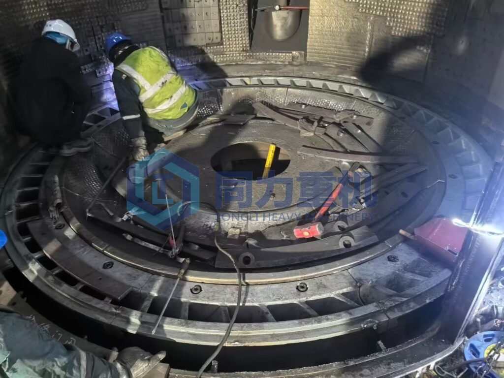
Design Principles for the Number and Dimensions of Liner Plates
Vertical roller mill grinding disc liners typically employ a segmented structure. The number of segments must comprehensively consider the grinding disc diameter, individual piece weight, lifting conditions, and installation accuracy requirements. For small-diameter grinding discs (φ2–3m), the liner is generally divided into 4–6 pieces, with the weight of each piece controlled below 2t. This allows for installation with manual labor and small lifting equipment, suitable for small to medium-sized vertical mills or retrofit projects. For large-diameter grinding discs (φ4–6m), the liner is usually divided into 8–12 pieces, with each piece weighing approximately 3–5t. Specialized lifting tools, positioning pins, and synchronous lifting devices must be used to ensure installation safety and accuracy. In terms of geometric design, the length-to-width ratio of a single liner plate is recommended to be controlled between 1.2–1.5:1. If the liner is too long and narrow, it is prone to bending deformation under concentrated loads from the grinding rollers, leading to localized stress concentration and premature fracture. A reasonable ratio can effectively improve the overall bending strength and service stability of the liner.
Joint Gap Control and Sealing Structure Design
The joint gap between the liners is a critical detail affecting the operational reliability of the vertical roller mill. In engineering practice, the width of the liner joint should be strictly controlled within the range of 2–5 mm. Excessive gaps can allow material to enter the back of the liner, causing it to loosen or even shift under centrifugal force and vibration; conversely, insufficient gaps may lead to compression under thermal expansion or load deformation, causing the liner to arch or crack at the edges. To prevent fine materials from intruding into the liner-grinding surface, high-temperature resistant rubber sealing strips or wear-resistant ceramic adhesive/high-temperature sealant are typically installed at the joint. This structure not only isolates the material but also absorbs a certain amount of thermal deformation and micro-vibration, significantly reducing the risk of wear on the back of the liner and corrosion of the grinding disc.
Liner Fixing Methods and Structural Optimization
The fixing method of segmented liners directly determines their impact resistance and operational reliability. Common engineering solutions mainly include the following two categories:
- Bolt fixing structure: This is currently the most widely used form. High-strength reamed bolts of grade 8.8 or higher are typically selected to ensure positioning accuracy and shear strength. The bolt heads must adopt a countersunk or countersunk head structure to ensure the flatness of the liner working surface and avoid interference with the grinding roller. This fixing method is simple in structure and easy to maintain, suitable for medium- and low-speed vertical mills (15–30 r/min) and general clinker and raw material grinding conditions.
- Dovetail groove fixing structure: This solution is more often used in high-end or high-load conditions. A dovetail groove is designed on the back of the liner, forming a mechanical self-locking structure with the corresponding boss on the grinding disc, achieving reliable fixing without bolts. Compared to bolt connections, the dovetail groove structure has stronger impact resistance and vibration resistance, making it particularly suitable for high-speed vertical mills or grinding high-hardness, highly abrasive materials (such as slag and ore). IV. Liner Material Selection and Operating Condition Matching.
Installation Accuracy Control and Operational Precautions
Before installing the liner, the grinding disc mounting surface must be thoroughly treated, requiring a flatness error ≤0.5 mm/m. Otherwise, uneven stress on the liner will occur, leading to localized abnormal wear. After installation, the liner height, radial runout, and overall concentricity should be re-measured to ensure they meet design requirements. During the initial commissioning of the vertical roller mill, a no-load or light-load break-in period of 2–4 hours is required. After the liner and grinding rollers have formed a stable contact state, the load can be gradually increased to the rated operating conditions to avoid cracking of the new liner under instantaneous impact loads. During operation, the liner fixing status should be checked regularly. If loose bolts, increased gaps, or sealing material failure are found, they should be addressed promptly to prevent liner displacement or premature failure.
What is the relationship between vertical roller mill grinding chamber and liner?
The grinding chamber is a closed space inside a vertical mill where materials are ground. Its geometric dimensions (diameter and depth) and chamber structure determine the layout and specifications of the liners. For example, the grinding chamber diameter of a large vertical mill can reach 5 to 8 meters, requiring segmented liners to fit the installation space. The operating parameters of the grinding chamber, such as temperature and pressure, are also closely related to the performance of the liners. High temperatures in the grinding chamber (above 200°C) will reduce the hardness of the liners and accelerate their failure. The sealing installation quality of the liners affects the negative pressure stability of the grinding chamber and prevents air and material leakage. The design differences between different brands of grinding discs directly lead to customized liner solutions. Taking the grinding disc structure of the Pfeiffer vertical mill as an example, the relationship between its design logic and liner type can be explained in detail as follows:
Pfeiffer vertical mills employ a segmented liner assembly structure
The surface of the grinding disc body has pre-drilled, regularly arranged bolt holes or mounting slots. This "drilling + segmented assembly" design dictates that the liners must be segmented wear-resistant plates, rather than integral liners. These segmented liners are usually fan-shaped, their dimensions perfectly matching the arc of the grinding disc segments. They are securely connected to the pre-drilled holes in the grinding disc body using high-strength bolts. The gap between adjacent liners must be controlled within 0.5mm to prevent material jamming and accelerated localized wear. The advantage of this design is that when a liner becomes excessively worn or damaged, it can be individually removed and replaced without requiring a complete shutdown for replacing the entire grinding disc liner, significantly reducing maintenance time and costs. In contrast, some brands of vertical mills (such as the Loesche LM series) have a one-piece cast grinding disc structure, and their liners often use a welded or integrally inlaid design, making installation and replacement more complex.
Does Grinding Chamber Wall Liner (Mill Housing Liner) equal to grinding table liner or not?
The grinding table liner of the vertical roller mill and the mill housing liner are not the same. They differ significantly in material, thickness and structural design. The core reason is that they bear completely different loads, wear types and working conditions. In practical applications, the replacement cycle of the grinding disc liner is typically 4000-8000 hours, while the inner wall liner of the middle shell can last for more than 10000 hours. The selection of materials and thicknesses for both must be determined comprehensively based on the material hardness, grinding pressure, and operating temperature to ensure the efficient and stable operation of the vertical cement mill.
| Comparison Dimension | Grinding Table Liner | Mill Housing Inner Wall Liner (Grinding Chamber Wall Liner) |
| Primary Material | High-chromium cast iron (Cr ≥ 20%, hardness HRC 58–62), Ni-Hard Type IV cast iron; for severe-duty applications, composite wear materials are used (e.g., tungsten carbide hardfacing layers) | Mainly wear-resistant steel plates (such as NM400 / NM500), low-alloy wear-resistant steel; in some cases, segmented high-chromium cast iron liners are used to balance toughness and basic wear resistance |
| Typical Thickness | 80–120 mm for large MPS series mills; 50–60 mm for smaller tables. Thickness is selected to match grinding pressure (15–20 MPa) | Typically 15–30 mm; designed only to resist light material scouring and abrasion, without exposure to high compressive loads |
| Structure & Installation | Segmented fan-shaped design, fastened to pre-drilled table holes using high-strength bolts. The working surface incorporates spiral or groove patterns matching the grinding table channels, with joint gaps ≤ 0.5 mm | Curved or rectangular segments, fixed by welding or bolting. Surfaces are usually flat or with shallow grooves, focusing on casing protection; dimensional accuracy requirements are lower than for table liners |
| Operating Conditions & Function | Directly subjected to high-pressure rolling from grinding rollers and intense material friction; governs material bed formation and grinding efficiency; a critical wear component | Subjected to erosive wear from airflow-borne material; protects the mill housing from abrasion and corrosion; does not participate directly in grinding and serves as a protective wear component |
Grinding Table Liner
The grinding table liner is installed on the horizontal grinding table and works directly with the grinding rollers. It is a core grinding component. The grinding table liner needs to withstand grinding pressure of 15-20 MPa and continuous sliding friction. Therefore, it must be made of high-hardness, high-wear-resistant high-chromium cast iron or similar materials, and its thickness must meet the requirements for strength and wear life. The modular design facilitates local replacement and reduces maintenance costs. It is a core grinding component and directly determines:
- Grinding efficiency
- Material bed formation
- Roller-table contact behavior
- Overall mill stability
Grinding Chamber Liner
The grinding chamber liner (also called grinding chamber wall liner, mill housing liner, or casing liner) is installed on the inner vertical wall of the mill housing. The inner wall liner of the middle shell only withstands slight erosion from airflow and materials, and its wear intensity is much lower than that of the grinding disc liner. Therefore, wear-resistant steel plates with better toughness and lower cost are used, and a thinner plate is sufficient to meet the protection requirements. Furthermore, the installation method is more flexible and adaptable to the structural characteristics of the shell. It is a protective liner, not a grinding element. Its function is to:
- Protect the mill casing from erosion and abrasion
- Withstand material and airflow scouring
- Maintain stable internal airflow
What factors should be considered when selecting a grinding table liner supplier?
When selecting a grinding table liner supplier for a vertical roller mill (VRM), several technical, operational, and commercial factors should be evaluated:
Quality
First, material composition and metallurgical quality are critical. The supplier should offer liner materials suited to your operating conditions, such as high-chromium cast iron, alloy steel, or composite liners. Key indicators include hardness profile, carbide distribution, impact toughness, and resistance to both abrasive and erosive wear. Consistency in chemical composition and heat treatment is essential to avoid premature cracking or uneven wear.
Design compatibility and accuracy
Second, design compatibility and profile accuracy must be considered. Grinding table liners must match the original OEM geometry or an engineered optimized profile to maintain proper material bed formation and grinding efficiency. Poor dimensional accuracy or incorrect liner profile can increase vibration, reduce output, and accelerate roller and table wear.
Supplier’s manufacturing capability
Third, assess the supplier’s manufacturing capability and quality control system. A reliable supplier should have in-house casting, machining, and heat treatment facilities, along with strict QC procedures such as chemical analysis, hardness testing, ultrasonic testing, and dimensional inspection. Certifications like ISO 9001 and documented traceability of each liner segment are strong indicators of reliability.
Proven performance and record
Another important factor is service life and proven performance. The supplier should be able to provide references, operating data, or case studies from similar VRM models (Loesche, FLSmidth, Pfeiffer, UBE, etc.) and comparable cement or slag applications. Performance guarantees or wear rate benchmarks are valuable for evaluating total lifecycle cost rather than just initial price.
Installation support and technical service
You should also consider installation support and technical service. Experienced suppliers can provide guidance on liner flipping schedules, wear pattern analysis, tightening torque, and commissioning checks. Post-installation support and failure analysis capability are especially important for large VRMs operating under high loads. Finally, evaluate commercial and supply chain factors, including lead time, spare part availability, logistics experience, and after-sales responsiveness. A competitive price is important, but it should be weighed against liner lifetime, mill stability, and reduced unplanned downtime to achieve the lowest cost per ton.
TONGLI Provide high quality grinding table liner:
Tongli offers a full range of wear-resistant materials—including high-chromium cast iron, alloy steel, and engineered composite liners, customized to match specific operating conditions such as feed abrasiveness, mill load, and grinding pressure. Through optimized chemical composition control and advanced heat-treatment processes, Tongli ensures uniform hardness profiles, stable carbide distribution, excellent impact toughness, and high resistance to both abrasive and erosive wear. This metallurgical consistency effectively minimizes premature cracking, spalling, and uneven wear, resulting in longer and more predictable liner service life.
TONGLI Design compatibility:
Tongli manufactures grinding table liners strictly according to OEM drawings or provides engineered optimized profiles based on operational data and material characteristics. Precise dimensional control and accurate liner geometry help maintain a stable material bed, reduce vibration, and ensure uniform load distribution between the grinding rollers and table. This not only improves grinding efficiency but also slows the wear rate of both rollers and table liners.
TONGLI's manufacturing capability
Tongli operates fully integrated in-house facilities covering casting, machining, and heat treatment, enabling strict control over every production stage. Each liner segment undergoes comprehensive quality inspections, including chemical composition analysis, hardness testing, ultrasonic testing, and dimensional verification. With ISO-certified quality management and full traceability from raw material to finished product, Tongli delivers consistent and reliable liner quality suitable for continuous industrial operation.
TONGLI's Proven performance and record
Tongli grinding table liners have been successfully applied in a wide range of VRM models, including Loesche, FLSmidth, Pfeiffer, and UBE mills, across cement raw meal, clinker, slag, and other abrasive materials. Supported by operational references, wear data, and performance benchmarks, Tongli focuses on reducing total lifecycle cost rather than simply offering low initial prices—helping customers achieve stable production, fewer shutdowns, and lower cost per ton.
Why Choose tongli vertical roller mill grinding table liner manufacturer?
Choosing Tongli means selecting more than a grinding table liner supplier—we are a vertical roller mill manufacturer with deep system-level expertise. Unlike standalone wear-part producers, Tongli designs, manufactures, installs, and commissions complete VRM systems. This gives us a comprehensive understanding of grinding mechanics, load distribution, material bed formation, and wear behavior under real operating conditions.
With over 20 years of OEM experience supporting Loesche vertical roller mills, Tongli has accumulated substantial practical knowledge in liner design optimization, material selection, on-site installation, and operational troubleshooting. Our liners are therefore engineered not only for wear resistance, but also for mill stability, grinding efficiency, and long-term operational reliability.
Because we manufacture the mill itself, Tongli grinding table liners are developed with a system-first approach, ensuring precise compatibility, predictable wear patterns, and extended service life. This integrated capability allows us to support customers throughout the entire lifecycle, from design and production to installation guidance and performance improvement, helping reduce downtime and achieve the lowest total cost per ton.
So above are the main reasons why we are your ideal partner for vertical roller mill liner, VRM spare parts, vertical roller mill grinding roller sleeve/tyre...etc.