


“These are all girth gears, just with different names.”
Girth Gear Assembly, Split Girth Gear, Bolted Girth Gear, Cast Steel Girth Gear, Forged Girth Gear, Dual-Segment Girth Gear, Ring Gear, Crown Gear, Ball Gear, and Main Drive Gear—these terms are often confusing but generally refer to the same component. The pinion is the only exception! In this article, we will clarify the differences, functions, materials, and structural designs of the component commonly referred to as the crown gear.
Let's start with the girth gear definition:
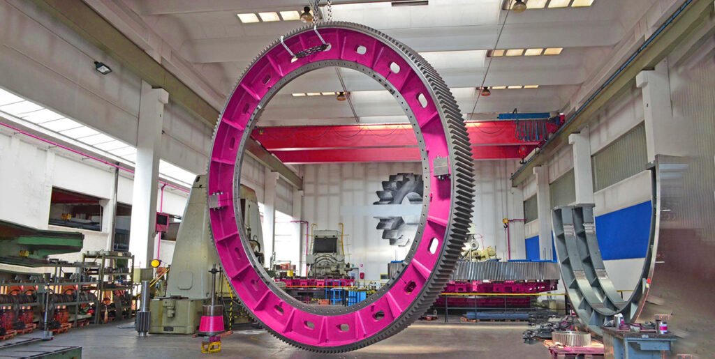
A girth gear, or gear ring, is a large circular gear designed to transmit torque between the main drive shaft and the driven shaft of heavy machinery. It is typically mounted around the outer circumference, often on the underside. Girth gears are essential components in large rotating equipment and are commonly used in rotary kilns, dryers, and ball mills, where their robust design ensures reliable operation under demanding conditions.
The importance of girth gear:

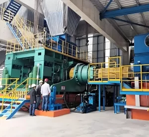
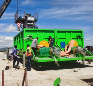
In industrial applications such as cement ball mills, ceramic grinding ball mills, lime rotary kilns, and compound fertilizer dryers, girth gears are a fundamental element of the drive system, although they represent only one component within the complete gear drive system. By carefully considering application-specific demands, installation space, and operating parameters, our girth gears are engineered to work seamlessly with pinions, intermediate gear units, and lateral gear drives to drive your equipment efficiently and reliably.
Girth gear for open gear arrangement and lateral gear drive
A conventional open gear arrangement typically consists of a main motor, a speed-reducing intermediate gear unit(reducer), and a pinion that engages directly with the girth gear. Through a combination of standardized solutions and custom-designed girth gears and pinions, we are able to deliver a fully tailored power train that is purpose-built for your exact operating conditions. For installations requiring higher power density within restricted space, the lateral gear drive offers a highly effective alternative. Its symmetrical casing design provides flexibility in positioning, enabling the drive train to be installed at the most suitable location around the mill. When the lateral gear drive is supplied together with the girth gear, precise matching between both components is ensured, resulting in optimal performance and reliability.
Girth gear manufacturer: Our Expertise in girth gear manufacturing
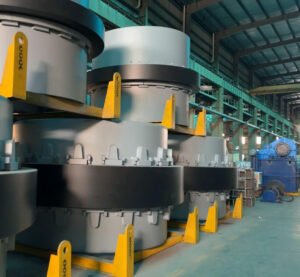
Beyond advanced manufacturing processes, the true strength of our girth gear manufacturing lies in the expertise of our engineers and machine operators. Trained in advanced engineering software and modern production techniques, they are capable of producing high-quality girth gears from a wide range of materials, strictly according to customer specifications. Depending on project requirements, we can manufacture either individual geared components or the entire power train. Drawing on in-depth engineering analysis and decades of practical experience, we also recommend design enhancements that improve component durability and operational stability. This approach ensures long-term, smooth, and reliable operation of your mill or kiln, both today and in the years ahead.
Working principle of girth gear:
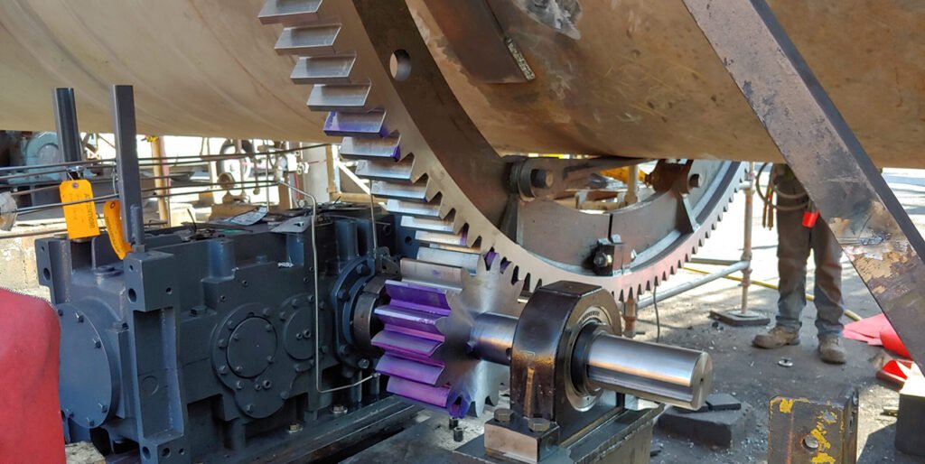
The operating mechanism of a girth gear centers on transferring rotational energy from a pinion to a large rotating cylinder or shell. The pinion, which is a smaller gear, meshes directly with the girth gear and is driven by a motor or drive system that supplies the required rotational force.
As the motor drives the pinion, the pinion teeth engage with the girth gear teeth, converting rotational motion into torque. This interaction causes the girth gear to rotate, and because the girth gear is rigidly mounted to the cylinder, the entire drum rotates as a single unit. This continuous rotation is fundamental to many industrial operations. In a ball mill, for example, cylinder rotation lifts and tumbles the grinding media, enabling material size reduction. In a rotary kiln, rotation supports uniform heating, mixing, and processing of the material inside the shell.
Power transfer between the pinion and girth gear relies on accurate gear meshing, where the contact forces between mating teeth generate the torque needed to rotate the cylinder. The effectiveness of this transmission is influenced by factors such as tooth geometry and surface quality, lubrication performance, and proper alignment between the pinion and the girth gear.
Effective lubrication plays a vital role in the reliability of a girth gear system. By reducing friction at the tooth contact surfaces, lubricants enhance transmission efficiency while minimizing wear and extending gear life. Depending on operating requirements—including load, speed, and temperature—different lubrication solutions may be used, such as mineral oils, synthetic oils, or greases, each selected to ensure stable and long-term operation of the girth gear and pinion assembly.
What materials are available for girth gears? And which one fits your application?
Ball mill large gear materials has 3 options: gray iron, cast steel and forgings, each adapted to different working conditions: gray iron (e.g., HT250, HT300) features excellent castability, wear resistance and low cost, suitable for small and medium-sized ball mills under low-speed, light-load and stable working conditions; cast steel (e.g., ZG45, ZG40Cr) has superior tensile strength, toughness and impact resistance compared with gray iron, applicable to medium and large ball mills under heavy-load and complex working conditions; forgings (e.g., 45# forged steel, 20CrNiMo alloy forged steel) have the finest grain structure, optimal mechanical properties and longest service life due to the elimination of internal defects through forging, ideal for large and extra-large ball mills under ultra-heavy-load and high-intensity continuous operation, with the highest cost among the three types. Now let;s introduce them one by one.
1. Steel Casting or Cast Steel Girth Gear: The main stream
Cast steel offers significantly higher tensile strength, toughness, and impact resistance than gray cast iron, making it well suited for ball mill girth gears operating under heavy loads, frequent start–stop cycles, and strong impact forces. Commonly used grades include ZG310-570 (ZG45), ZG340-640 (ZG55), and alloy cast steels such as ZG40Cr and ZG35SiMn. Through alloying with elements like Cr, Mn, and Si, the hardness and wear resistance of cast steel girth gears can be further enhanced, with tooth surface hardness reaching HB220–280 after quenching and tempering. Cast steel blanks are capable of meeting the forming requirements of large-diameter gears exceeding 3 meters, although the casting process must be carefully controlled to prevent defects such as shrinkage cavities and porosity. While the cost and machining difficulty are higher than those of gray cast iron, cast steel girth gears are widely applied in medium and large ball mills, high-speed and heavy-load applications, and complex operating conditions, such as raw material mills in cement production lines and main ball mills in mineral processing plants.
Adventages of cast steel girth gear:
- High Torque Capacity: Girth gears are specifically designed to handle and transmit very large torque loads between the main drive shaft and the driven shaft, making them well suited for heavy machinery applications.
- Robust and Durable Design: By using high-strength materials, the girth gear structure provides long service life and dependable performance, even under continuous and demanding operating conditions.
- Circumferential Mounting: Mounted around the circumference of the equipment, girth gears make efficient use of available space while contributing to improved operational stability.
- Precision Gear Teeth: The gear teeth are manufactured for accurate meshing, which helps reduce vibration and wear while maintaining smooth and efficient power transmission.
- Easy Maintenance: The girth gear configuration supports straightforward inspection and maintenance, helping to minimize downtime and lower overall operating costs.
2. Forged gear ring technology
Our capabilities in forged gear ring technology are the result of more than five decades of accumulated experience, supported by long-term cooperation with world-famous mill manufacturers and technical universities and institute like American Gear Manufacturers Association (AGMA), we contribute directly to the development of gear-rating calculations, service factors, and other design standards. Ongoing investment in both technology and engineering expertise continues to expand and strengthen our capability. Currently, we have more than 1200 girth gears are operating worldwide, providing proven reliability across the cement and compound fertilizer industries.
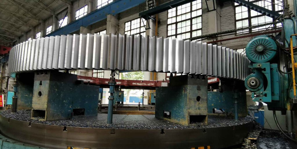
Manufacturing Process of our Forged Gear Ring
Our advanced manufacturing techniques allow girth gears to deliver stable power transmission, high wear resistance, and extended service life in both mills and kilns. The production of fabricated girth gears follows a carefully controlled, multi-stage process that includes comprehensive quality inspections after welding and tooth cutting(gear hobbing). Our fabricated girth gears are manufactured using forged gear rim material combined with electro-welded gear bodies. Compared with girth gears produced from cast base material, this approach involves a more advanced and controlled manufacturing process, resulting in higher structural reliability. The uniform and homogeneous grain structure of the forged rims ensures consistent material properties throughout the entire toothing. As a result, common casting defects such as hot tears, porosity, and shrinkage are eliminated, producing a stronger and more dependable girth gear. For ductile cast iron and cast-iron girth gears, raw materials are sourced exclusively from our own foundries. We guarantee stable and high-quality material performance.
The process begins with rolling and forging premium-grade material into the required ring dimensions. Structural components such as webs, ribs, and junction plates are then welded to the forged rim using qualified procedures. All assemblies are subjected to non-destructive testing, followed by post-weld heat treatment. Subsequent rough and finish machining brings the girth gear to its final dimensions. In the final stage, tooth geometry, runout, hardness, and additional parameters are thoroughly measured and documented during the closing inspection. To meet specific operating conditions, our experienced engineers apply advanced finite element modelling (FEM) tools to design girth gears precisely matched to your application. Supported by modern production facilities and continuous technological development, we ensure that our girth gears are engineered to meet current demands while remaining fully prepared for future operating challenges.
3. Cast Iron girth gear: Spheroidal Graphite Iron (SGI) Ductile iron ring gear
Suitable for small and medium-sized ball mills, low-speed, light-load, and stable operating conditions, such as small ball mills in laboratories and auxiliary fine crushing ball mills in mineral processing plants. Ductile iron girth gear, is a large-diameter gear ring designed for torque transmission in heavy-duty rotating equipment such as ball mills, rotary kilns, dryers, and grinding mills. Unlike gray cast iron, SGI contains graphite in a spheroidal (nodular) form. The material provides higher tensile strength and impact resistance than gray cast iron, while also delivering good vibration damping and wear resistance, which are important for large open gear drives. SGI girth gears can be cast in large diameters, often in segmented or split configurations for easier transportation and on-site assembly.
Features:
- It exhibits excellent casting properties, enabling the casting of large-sized gear blanks with complex shapes. The castings also exhibit low internal stress and are less prone to deformation.
- Graphite, distributed in flakes, possesses good anti-friction and self-lubricating properties, resulting in low noise and minimal wear during meshing.
- It has relatively low cost and good machinability, facilitating subsequent finishing processes such as turning and gear hobbing.
- Disadvantages include poor tensile strength and impact resistance, insufficient toughness, and a susceptibility to tooth root fracture and chipping under overload or frequent start-stop conditions.
Adventages:
Spheroidal Graphite Iron (SGI) gear castings provide excellent material quality, with hardness values up to 309 BHN, making them well suited for heavy-duty girth gear applications. The inherently lower stiffness of SGI compared to steel improves load sharing across the gear face and between individual teeth, which helps reduce pitting, minimizes localized stress, and ensures a long-lasting and reliable gear performance. To further optimize the design, finite element analysis (FEA) is used to model gear deflection under operating loads, allowing the geometry and material properties to be precisely matched for optimal durability and service life.
4. Austempered Ductile Iron (ADI) Segmented Girth Gear
Austempered Ductile Iron (ADI) is a high-performance cast iron material that has become an important choice for demanding gear applications such as segmented girth gears used in ball mills, SAG mills, rotary kilns, and other heavy-duty rotary equipment. ADI is produced by subjecting conventional ductile iron to a specialized austempering heat treatment process, resulting in a unique ausferritic microstructure that provides an exceptional combination of mechanical properties. Compared with standard ductile iron, ADI exhibits significantly improved tensile strength, high fatigue resistance, and superior wear performance, making it well suited to withstand the cyclic bending and contact stresses experienced by girth gear teeth under heavy loads. ADI can achieve tensile strengths that are comparable to or even exceed some steel grades while retaining good ductility and fracture toughness, which contributes to gear durability and resistance to crack propagation. In practice, the enhanced material characteristics of ADI allow girth gears to deliver longer service life, reduced wear rates, and effective load transfer, even in applications involving large modules and substantial torque. The relatively high contact fatigue strength of ADI is a key factor in maintaining gear reliability over extended operating periods. Additionally, its inherent vibration-damping qualities and ability to be produced with near-net shapes make ADI a cost-effective and performance-driven material choice for segmented girth gear castings.
What is Austempered Ductile Iron (ADI)?
Austempered Ductile Iron (ADI) is a class of heat-treated ductile cast iron developed to achieve a combination of high strength, fracture toughness, fatigue resistance, and wear resistance that is comparable to many alloy steels, while maintaining the inherent castability and design flexibility of ductile iron. The defining characteristic of ADI is the austempering heat treatment process, in which ductile iron is austenitized and then isothermally transformed at controlled temperatures. This process produces a distinctive ausferritic microstructure, consisting of acicular ferrite and high-carbon stabilized retained austenite. This microstructural configuration provides ADI with high tensile strength, useful ductility, excellent resistance to cyclic fatigue, and enhanced wear performance, without the brittleness typically associated with high-strength cast irons. At the same time, ADI preserves adequate machinability and is well suited for the production of large, complex cast components, such as segmented girth gears, where both mechanical performance and manufacturing efficiency are critical.
| Element | Typical Range (%) | Function |
| Carbon (C) | 3.4 – 3.8 | Promotes graphite formation and strength |
| Silicon (Si) | 2.2 – 2.8 | Enhances graphitization, promotes ferrite |
| Manganese (Mn) | 0.1 – 0.3 | Controls hardenability, kept low to avoid carbide formation |
| Magnesium (Mg) | 0.03 – 0.06 | Essential for spheroidizing graphite |
| Copper (Cu) | 0.1 – 0.5 (optional) | Improves hardenability and tensile strength |
| Nickel (Ni) | 0.5 – 2.0 (optional) | Enhances toughness, stabilizes austenite |
| Molybdenum (Mo) | 0.1 – 0.3 (optional) | Improves high-temperature strength |
| Phosphorus (P), Sulfur (S) | ≤0.03 | Kept to a minimum to prevent brittleness |
| Aspect | Austempered Ductile Iron (ADI) | Standard Ductile Iron (Grade 65-45-12, etc.) |
| Tensile Strength | 800–1400 MPa | 450–650 MPa |
| Elongation | 2–13% (depending on grade) | Up to 18%, lower for higher strength grades |
| Hardness | 250–550 HB | 130–200 HB |
| Wear Resistance | Excellent (self-lubricating under load) | Moderate |
| Fatigue Strength | 200–300 MPa | 120–180 MPa |
| Cost | Slightly higher due to heat treatment | Lower due to simpler processing |
5. Fabricated Steel Girth Gear for Ball Mills
A fabricated steel girth gear is a large-diameter drive gear used in ball mills, designed and manufactured using a welded steel structure rather than a single-piece casting. This type of girth gear typically consists of a forged steel gear ring forming the outer toothed rim, which is integrally welded to a fabricated inner web structure made of steel plates and stiffening ribs. Together, these components form a complete, high-strength girth gear assembly. Proven alloy steels are used in the construction of the fabricated girth gear rim, achieving minimum hardness values ranging from 185 to 350 BHN and high impact strength, typically around 36 J and reaching up to 89 J for demanding applications. The gear segment rims are hot forged using a proprietary hot-forming process, ensuring superior material consistency while significantly reducing residual stresses. In addition, finite element analysis (FEA) is employed to model stress distribution throughout the gear structure, enabling optimized material selection and ensuring robust, reliable operation under high load conditions.
Unique Manufacturing procedure: Fabricated Steel Girth Gear for Ball Mills
From a manufacturing perspective, the gear rim is produced by open-die forging or ring rolling, followed by rough machining, tooth cutting (hobbing or shaping), and heat treatment to achieve the required tooth profile accuracy and mechanical properties. Separately, the inner structure—including the hub ring, web plates, and reinforcement ribs—is fabricated from high-quality carbon steel or low-alloy steel plates through cutting, forming, and precision welding. After welding, the entire girth gear assembly undergoes stress-relief heat treatment to eliminate residual welding stresses and ensure dimensional stability. Final machining is then performed on the bore, mounting faces, and reference surfaces to ensure concentricity, runout control, and proper alignment with the mill shell. Depending on application requirements, the gear teeth may receive surface hardening or localized heat treatment to improve wear resistance and service life. Compared with traditional cast steel or cast iron girth gears, fabricated steel girth gears offer several advantages, including:
- Higher structural strength and toughness
- Reduced risk of casting defects such as porosity or shrinkage cavities
- Greater flexibility for large diameters, where single-piece casting becomes impractical
- Improved fatigue resistance under high torque and variable load conditions
But most importantly the delivery time.
Manufacturing Lead Time as a Selection Factor for fabricated steel Girth Gears
A standard cast steel girth gear requires multiple time-consuming steps, including pattern design and fabrication, mold preparation, melting and pouring, solidification and cooling, heat treatment, defect inspection, and extensive machining. For large-diameter ball mill girth gears, the casting cooling and stress-relief process alone can take several weeks to avoid internal cracking or distortion. Typical lead time: 4–6 months (and sometimes longer for very large sizes or defects are found) while A fabricated steel girth gear eliminates the need for large casting molds and long cooling cycles. The forged or ring-rolled gear rim is typically available as a semi-finished component, while the inner web and hub structure are fabricated from steel plates using cutting and welding processes.
- No pattern or mold manufacturing
- Faster forging/ring-rolling availability
- Parallel processing of rim machining and inner structure fabrication
- Lower risk of rejection due to internal defects
After welding, stress-relief heat treatment and final machining are completed in a controlled and predictable timeframe, making scheduling more reliable. For operating cement and mining plants, prolonged downtime can result in significant production losses. In such cases, a fabricated steel girth gear provides a practical solution.
Replacement and Repair Advantages of Fabricated Steel Girth Gears
One significant advantage of a fabricated steel girth gear is its modular and repair-friendly design, which allows partial replacement or refurbishment in the event of wear or damage—an option that is generally not feasible with one-piece cast girth gears. The Partial Replacement Capability is execellent, In a fabricated girth gear, the outer forged or ring-rolled gear rim and the inner welded web/hub structure are separate functional components joined by welding. If tooth wear, pitting, or localized damage occurs during service, it is often possible to:
- Replace only the toothed gear rim, while retaining the inner web and hub
- Cut out and reweld damaged segments of the rim in segmented fabricated designs
- Perform on-site or workshop refurbishment, depending on damage extent
This approach can significantly reduce replacement cost, manufacturing time, and downtime, particularly for large ball mills where complete gear replacement would be logistically challenging.
Fabricated Girth Gear Comparison with Cast Steel Girth Gears
A cast steel girth gear is typically manufactured as a single, monolithic component. Once the gear teeth are severely worn or cracked:
- The entire girth gear must be recast or remanufactured
- Repair options are limited and often uneconomical
- Lead time for replacement is considerably longer
As a result, cast girth gears generally require full replacement rather than partial repair, increasing both cost and downtime.
Practical Limitations of fabricated girth gear:
While partial replacement is a major advantage, it is important to note:
- Partial replacement is feasible only if the inner web and hub structure remain within allowable stress and alignment tolerances
- Welded replacement sections must undergo strict welding procedure qualification (WPS), post-weld stress relief, and dimensional inspection
- Not all fabricated girth gears are designed identically; segmented rim designs offer the greatest repair flexibility
Therefore, repairability should be considered during the original design stage, especially for mills operating under severe load conditions.
Fabricated girth gear vs steel casting girth gear pros and cons:
| Aspect | Cast Steel Girth Gear | Fabricated Steel Girth Gear |
| Replacement scope | Full gear replacement | Partial or full replacement possible |
| Rim-only replacement | Not feasible | Feasible in many designs |
| Repair lead time | Long | Shorter |
| Maintenance cost | High | Lower |
| Suitability for emergency repair | Poor | Excellent |
How to choose the right material for the girth gear?
1. Prioritize matching the ball mill specifications and load: small mills should use gray cast iron, medium mills should use cast steel, and large/extra-large mills should use forged steel.
2. Consider the severity of operating conditions: gray cast iron is strictly prohibited for scenarios with frequent start-stop cycles and high impact loads.
3. Balancing cost and lifespan: if the mill's annual operating time exceeds 7000 hours, forged steel gears are recommended due to their lower long-term overall cost.
Steel casting girth gear vs Iron casting girth gear vs Forged girth gear comparison table:
| Performance Index | Gray Cast Iron (HT300) | Cast Steel (ZG45) | Forged Steel (45#) |
| Tensile Strength (MPa) | 300 | 570 | 600 |
| Impact Toughness (J/cm²) | 1–3 | 15–20 | 25–30 |
| Tooth Surface Hardness (HB) | 180–220 | 220–280 | 280–320 (after quenching & tempering) |
| Impact Resistance | Poor | Good | Excellent |
| Cost | Low | Medium | High |
| Applicable Working Conditions | Light load, stable operation | Medium to heavy load, complex conditions | Heavy load, high-intensity duty |
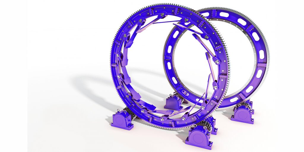
Two mounting types of girth gear: Flange or spring mount?
The gear and pinion drive assembly is one of the most widely used rotary drum drive systems in the market. When utilizing a gear and pinion drive, a critical design decision is how the girth gear will be affixed to the drum. This decision has a significant impact on the service life, operational stability, and reliability of a high-quality girth gear, making proper selection essential. There are four primary girth gear mounting methods. Here we will focuses on the two most commonly used girth gear mounting systems and the key factors to consider when selecting between them. A girth gear requires a mounting system that ensures structural integrity and provides adequate support as the gear rotates under variable load conditions, and in many cases, under thermal expansion and stress. In practice, girth gears are typically installed using one of two mounting styles: the spring-mounted girth gear or the flange-mounted girth gear. Both mounting methods provide effective solutions for rotary kiln, ball mill, and dryer applications; however, each approach presents its own distinct advantages, limitations.
1. Spring-Mounted Girth Gears: Designed for high temperature rotary drum
The spring-mounted girth gear is the most widely used mounting method and represents a flexible connection system between the girth gear and the mill shell or drive-end support. Unlike rigid mounting, this design secures the rectangular-section girth gear to the drum through elastic components, typically spring arm spokes, coil springs, or rubber spring elements, allowing controlled relative movement during operation.
Spring mounted girth gear structure:
Structurally, the system consists of spring supports welded or bolted to the end face of the girth gear hub or the rear side of the gear ring. During installation, spring elements are positioned between these supports and the connection seats on the mill cylinder, and the spring preload is carefully adjusted to control gear coaxiality, alignment accuracy, and gear meshing clearance. This configuration enables the drum shell to expand and contract beneath the gear without imposing excessive stress on the gear teeth or mounting components.
Adventages of spring mounted girth gear:
The key advantage of the spring-mounted system lies in its excellent shock absorption and vibration damping capability. The flexible spring plates respond dynamically to variable operating loads, effectively absorbing impact forces caused by uneven material feeding, fluctuations in material hardness, and transient load changes. This reduces gear meshing vibration and noise, minimizes stress concentration, and significantly lowers the risk of tooth surface overload wear, pitting, or tooth breakage. Additionally, the design compensates for thermal expansion and contraction of the mill shell, preserving the structural integrity, concentricity, and long-term service life of the girth gear.
Cost efficiency of spring mounted girth gear:
From a cost and application standpoint, the spring-mounted girth gear is more economical than a flange-mounted alternative and is therefore widely adopted in ball mills, rotary kilns, and rotary dryers. It is particularly well suited for wet ball mill applications in the mineral processing and cement industries, where operating loads fluctuate significantly and the mill cylinder is more susceptible to deformation due to slurry temperature variations.
Drawback and disadventage of spring mounted girth gear:
However, despite its operational advantages, the spring mount design is more complex to install and considerably more difficult to flip or replace compared to a flange-mounted girth gear, requiring precise installation procedures, careful preload adjustment, and longer maintenance downtime.
2. Flange-Mounted Girth Gears: Rigid Connection
The flange-mounted girth gear is the most commonly used rigid connection mounting method for rotary equipment. Its core structural feature is a precision-machined flange plate integrated into the hub end of the girth gear, which is bolted directly to a mating flange welded to the mill cylinder end plate or drive-end support. This configuration forms a rigid mechanical interface between the girth gear and the rotating shell.
Featuers of Flange-Mounted Girth Gears:
From a manufacturing and installation standpoint, the flange-mounted system imposes strict requirements on machining accuracy and assembly precision. The flange mating surfaces must undergo high-precision machining to ensure flatness and alignment, typically achieving a surface roughness of Ra ≤ 3.2 μm, with all burrs, contaminants, and oil residues fully removed prior to assembly. During installation, reamed bolts or high-strength fasteners equipped with spring washers or locking nuts are used, and symmetrical pre-tightening is performed. Bolt preload must be precisely controlled using a torque wrench, generally set at 60%–70% of the bolt material’s yield strength. Following assembly, a dial indicator is used to measure the radial runout and axial (end) runout of the girth gear outer diameter, ensuring alignment deviations do not exceed 0.05 mm per meter, thereby maintaining proper gear concentricity and meshing accuracy.
Adventages of Flange-Mounted Girth Gears:
The primary advantages of the flange-mounted girth gear include high connection rigidity, excellent torsional stiffness, and high power transmission efficiency. This rigid coupling ensures synchronous rotation between the girth gear and the mill cylinder without relative slip, making it well suited for high-power and high-speed applications, such as cement clinker ball mills and metallurgical slag mills. In addition, compared to spring-mounted designs, the flange-mounted girth gear is easier to install in the field and can be flipped or repositioned for maintenance with reduced labor and downtime, provided alignment conditions are met.
Limitations of Flange-Mounted Girth Gears:
However, the flange-mounted design has inherent limitations. Because it is a rigid mounting system, it offers no inherent flexibility to accommodate thermal expansion or contraction of the mill shell. As a result, thermal deformation must be addressed at the design stage by reserving appropriate thermal expansion clearances, and the maximum allowable drum operating temperature is typically limited to approximately 350°F (≈175°C). Any deviation in flange machining accuracy or uneven bolt preload can lead to gear eccentricity, resulting in uneven load distribution, contact fatigue wear, pitting, and accelerated tooth surface damage.
When to use Flange-Mounted Girth Gears?
For applications involving significant temperature fluctuations or shell deformation, rotary equipment manufacturers often favor the spring-mounted girth gear. Nevertheless, when operating conditions permit, the flange-mounted girth gear remains a preferred solution for high-load, high-speed, and high-efficiency transmission systems requiring maximum structural rigidity and precise torque transfer.
3. Keyed Connection Mount for ball mill girth gears:
Keyed Connection Mount realizes the mechanical connection between the large gear and the ball mill main shaft or cylinder hub by relying on connecting parts such as flat keys and splines, belonging to the semi-rigid connection method.
Installtion procedure for keyed connection mount ball mill girth gears:
During installation, first, keyways are machined on the mill main shaft (or cylinder hub shaft head) and the inner hole of the large gear hub, then the flat key (or spline) is embedded into the shaft-side keyway, and then the large gear is heated to 80~120℃ (using thermal expansion and contraction to increase the inner hole diameter), sleeved onto the shaft head, and the key is precisely matched with the gear keyway. After cooling, the gear inner hole shrinks to form an interference fit with the shaft and the key. Flat key connection has the advantages of simple structure and low cost, and is suitable for small and medium-power ball mills (such as laboratory small mills and fine grinding equipment in the chemical industry).
Limitations for keyed connection mount girth gears:
However, it has limited torque transmission capacity, and stress concentration is prone to occur at the keyway, which may lead to shear deformation of the key or wear of the gear hub keyway during long-term operation. Spline connection (mostly involute splines) can transmit larger torque due to its large contact area and uniform stress distribution, and is mostly used for the drive end connection of heavy-duty ball mills. Its installation accuracy requirements are higher, and spline gauges need to be used to detect the tooth side clearance to ensure meshing accuracy.
Girth Gears Shrink Disk Mount
Shrink Disk Mount is a keyless rigid connection method, with the core component being the shrink disk, a metal kit matched by inner and outer tapered surfaces. By tightening the high-strength bolts on the shrink disk, axial displacement is generated on the inner and outer tapered surfaces, thereby expanding the inner hole of the large gear hub and the shaft head of the mill cylinder, and transmitting torque by relying on friction force generated by interference fit.
Girth Gears Shrink Disk Mount installation guidance:
During installation, there is no need to machine keyways; it is only necessary to ensure the surface roughness (Ra1.6~3.2μm) and cylindricity of the hub inner hole and shaft head. The shrink disk is placed into the gap between the gear hub and the shaft head, and the bolts are tightened symmetrically to generate radial expansion force on the shrink disk, realizing gap-free fastening between the gear and the shaft.
Girth Gears Shrink Disk Mount adventages:
The advantages of shrink disk connection are good alignment and uniform stress distribution, no stress concentration caused by keyways, which can effectively extend the service life of the gear and the shaft; at the same time, it is convenient to disassemble, and the gear can be separated from the shaft only by loosening the bolts, facilitating maintenance and overhaul. This method is suitable for ball mills with high installation accuracy requirements and frequent maintenance needs (such as multi-variety material grinding equipment in the chemical industry).
Girth Gears Shrink Disk Mount limitations:
However, it has strict requirements on the material and machining accuracy of the shrink disk, which needs to be made of alloy steel and undergo heat treatment (hardness HRC45~55), otherwise, shrink disk slippage failure is prone to occur.
4. Tangential Plate Girth Gear Connection
A tangent plate connection, also known as a tangential plate girth gear mounting, is a proven and widely used method for fastening large-diameter girth gears to the shell of rotary kilns, ball mills, and other heavy rotating equipment. In this design, a series of high-strength steel plates (tangent plates) are arranged tangentially around the circumference of the girth gear. Each plate is securely bolted to both the girth gear and the kiln or mill shell, forming a flexible yet robust torque-transmission system. This connection method is especially suited for large, heavy girth gears where thermal expansion, structural deformation, and alignment tolerance must be carefully managed.
Tangential Plate Girth Gear Structural Design and Arrangement:
From a structural perspective, the tangent plates act as mechanical links that connect the girth gear to the rotating shell without creating a rigid, fully constrained joint. Each plate is typically connected to machined or cast mounting surfaces on the gear and to welded pads on the shell. By distributing multiple plates evenly around the circumference, the system ensures that forces remain balanced during operation, even under high torque and variable loading conditions.
- Even circumferential distribution of plates
- Balanced structural loading
- Reduced local stress concentrations
Tangential Plate Girth Gear Connection Torque Transmission Mechanism
Torque transmission in a tangent plate connection occurs through tangential forces developed in the plates as the girth gear rotates. When the pinion drives the girth gear, the transmitted torque is shared among all tangent plates, with each plate carrying only a portion of the total load. This load-sharing mechanism significantly reduces peak stresses compared to keyed or rigid flange connections, resulting in improved fatigue resistance and longer service life of both the gear and fastening components.
- Torque transferred through tangential plate forces
- Multiple plates share the total load
- Lower stress per connection point
Thermal Expansion and Flexibility
One of the most important advantages of the tangent plate connection is its ability to accommodate thermal expansion and structural deformation. Rotary kilns and large mills operate under conditions where temperature gradients, shell ovality, and axial movement are unavoidable. The tangential plate design allows slight relative movement between the girth gear and the shell, helping maintain correct tooth alignment and preventing excessive stress on the gear rim and bolts during thermal cycling.
- Allows thermal expansion of the shell
- Compensates for shell deformation and ovality
- Protects gear teeth and fasteners from overstress
Load Distribution and Structural Benefits
In addition to mechanical performance, tangent plate connections offer practical benefits during installation and maintenance. The system allows in-situ adjustment during commissioning, making it easier to achieve proper gear alignment. Individual plates or bolts can be inspected and replaced without dismantling the entire girth gear, which is especially valuable for large equipment where downtime and lifting capacity are critical concerns.
Which girth gear connection method fits you?
The selection between the two mounting methods primarily depends on whether thermal expansion and contraction are expected during operation. In most cases where thermal effects are present, the spring-mounted design is preferred. When thermal stress is not a concern, the decision becomes a matter of balancing initial cost against installation complexity, maintenance effort, and labor requirements.
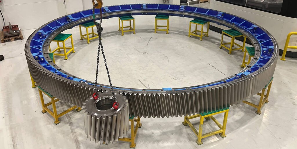
What is a pinion?
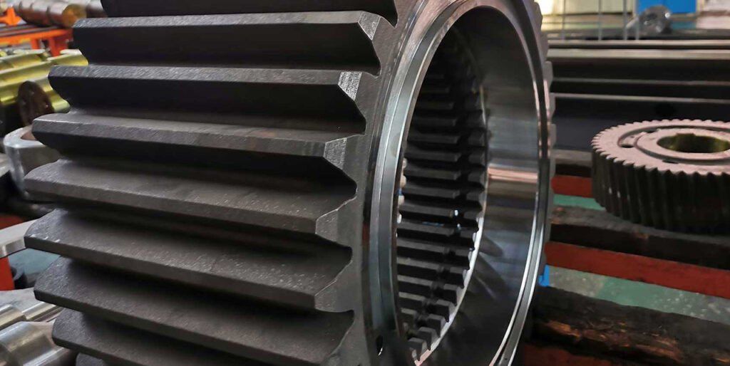
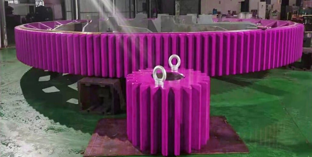
The pinion is a smaller gear that directly meshes with the girth gear and is mounted on a shaft connected to the driving mechanism. Through precise tooth engagement, the pinion drives the girth gear and transfers rotational motion and torque to the rotary equipment. Both the pinion and girth gear are produced from high-strength materials to handle continuous load transmission. Correct alignment between the pinion and girth gear, along with proper lubrication, is critical to reducing friction, preventing abnormal wear, and maintaining efficient power transmission.
Designed for Long Service Life
Within a girth gear drive system, pinions operate as the primary load-carrying components, experiencing significantly higher wear and fatigue cycles than the girth gear itself. For this reason, the correct selection and matching of pinion material, surface hardness, heat treatment, and tooth quality with the mating girth gear is critical to achieving long service life and stable operation. Proper compatibility between the pinion and gear ensures uniform load distribution, reduced tooth wear, and reliable performance under continuous heavy-duty operation. When production requirements change—such as increased throughput, higher driver power, or modified operating speed—custom pinion solutions can be provided. Wherever possible, existing envelope dimensions, including face width and center distance, are maintained to avoid extensive mechanical modifications and minimize shutdown time during upgrades or replacements.
Tailored Pinion Designs for Cement Applications
Pinion designs vary widely depending on application requirements, operating conditions, and installation constraints. Solutions are available in both helical and spur configurations, with options for bored (shell-type) pinions or integral one-piece designs. To accommodate alignment variations and improve load sharing, self-aligning pinion arrangements can also be incorporated. All pinions are manufactured from forged alloy steel and can be supplied with a range of heat treatment options, including through-hardening, quenching and tempering, or carburising and grinding, depending on load, speed, and wear requirements. These processes ensure the necessary strength, fatigue resistance, and surface durability for demanding cement industry environments.
Complete Drive and Accessory Solutions
In addition to pinions, a full range of accessory components is available to support the complete girth gear drive system. These include pinion shafts and bearings, tangential spring mounts, gear guards, lubrication systems, and gear joint hardware. For integrated solutions, complete drive systems can be supplied, including auxiliary drives such as emergency or inching drives, ensuring safe operation during maintenance and startup. All pinion and drive solutions are custom engineered to meet the specific requirements of cement applications, providing reliable performance, ease of maintenance, and long-term operational stability.
For more details about Pinion chekc out our product page: Pinion for ball mill and rotary kiln!
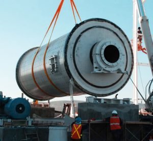
Girth Gear Installation & Replacement Guide:
Because improper installation can affect the integrity and lifespan of gears, Tongli recommends that the installation or replacement of gears for ball mills, rotary kilns, or dryers be performed by our installation engineers. Tongli provides installation/replacement and supervision services. The time required for gear replacement depends on several factors. Generally, gear replacement takes an average of three to six days, with gear size and installation method affecting the required time. The ease of access to the rollers also affects the replacement process time. For more informations about rotary kiln drive type click here!
How to install girth gear correctly?
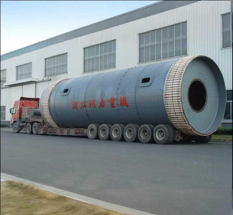
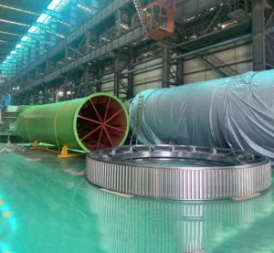
Because of the large size of the girth gear, along with limitations in foundry casting capacity, road transportation constraints, and on-site installation requirements, only small gear diameter less than 3m is manufactured into single piece. Big girth gear is typically produced in two semicircular segments or in multiple sections. These segments are transported individually and then assembled on site, where they are connected using high-strength bolts and mounted tangentially to the kiln shell through spring plates.
In rotary kiln applications, the girth gear is usually positioned near the mid-length of the kiln shell. This location allows the kiln shell to experience more uniform stress distribution during operation, while also keeping the gear away from the high-temperature zone at the firing end and reducing exposure to excessive dust. For reliable kiln operation, the girth gear must be installed with high precision: the centerline of the girth gear must coincide exactly with the centerline of the kiln cylinder. Improper alignment can lead to abnormal gear mesh, accelerated wear, vibration, and premature failure. There are two primary methods for connecting the girth gear to the kiln body: tangential connection and axial connection, each selected based on kiln size, operating temperature, and load conditions.
How is the tangential connection of the girth gear done?
With a tangential connection, the kiln girth gear is mounted onto spring plates that are oriented tangentially to the kiln shell. One side of the spring plate is fixed to the kiln body and backing plate, while the opposite side is bolted directly to the girth gear. Backing plates may be inserted at the joint surfaces to allow fine adjustment of the gear position. This configuration enables precise alignment, ensuring that the center of the girth gear matches the center of the kiln shell, while also allowing for thermal expansion during kiln operation.
How is the axial connection of the girth gear done?
In an axial connection, the girth gear is secured to elastic steel plates arranged parallel to the kiln cylinder axis. Typically, two circular rows of backing plate seats are installed on the kiln shell, with 8 to 15 elastic steel plates positioned between them. These plates are fixed to the kiln body using rivets, and the girth gear itself is attached to the steel plates with screws or bolts. This mounting method provides axial flexibility and accommodates shell deformation under thermal and mechanical loads. During installation of the drive system, particular attention must be paid to alignment: the centerlines of the girth gear and pinion gear must remain parallel to ensure correct gear mesh and smooth power transmission. Accurate alignment at this stage is critical to minimizing noise, vibration, and uneven tooth loading throughout the service life of the girth gear.
How to replace girth gear correctly?
Pinion Gear Replacement
As part of a girth gear replacement, TONGLI strongly advises replacing the pinion gear at the same time. Installing a new girth gear alongside a worn pinion gear can accelerate tooth wear and compromise the service life of the new component. Replacing both gears simultaneously not only protects the new girth gear from premature damage but also eliminates the need for a second shutdown that would otherwise be required to change the pinion gear later.
Gear Mounting Replacement
The selection of the gear-mounting system depends on operating conditions, load requirements, and whether the rotary drum is exposed to heat, such as in a dryer or kiln. TONGLI provides two proven gear-mounting styles: flange-mounted and spring-mounted designs, each suited to specific thermal and mechanical demands. During a girth gear replacement project, we recommend the replacement of all gear mounting hardware to ensure proper load distribution and long-term reliability. In certain situations, limited reuse of existing hardware may be possible; however, a gear replacement presents an ideal opportunity to re-evaluate the mounting style and confirm that it remains appropriate for current operating conditions.
Rotary Drum Alignment
If inspection reveals that girth gear damage was caused by trunnion misalignment, corrective action must extend beyond gear replacement alone. Following installation of the new girth gear and pinion gear, a complete trunnion realignment should be carried out. Proper alignment of the rotary drum ensures correct gear mesh, minimizes uneven loading, and prevents premature wear of the newly installed components.
Engineering Support and Supply Scope
For assistance with replacement girth gears, pinion gears, or other rotary drum components, please contact the TONGLI Customer Service Team for a detailed quotation. In addition to supplying individual components, TONGLI is fully capable of providing the complete drive assembly, ensuring compatibility, accurate alignment, and reliable long-term operation of your rotary equipment.
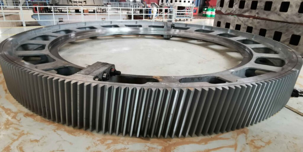
Split Girth Gear vs Bolted Girth Gear vs Segmented Girth Gear How Many Pieces Can a Girth Gear Have?
Usually a girth gear can have be divided into two, four, six, or eight segments. Ball mill crown gear and rotary kiln girth gears typically employ either an integral or segmented structure. The exact number of segments is not standardized and depends primarily on the gear diameter, module, manufacturing capabilities, transportation conditions, and on-site installation requirements. In engineering applications, small ball mills often use integral gears, while medium and large ball mills commonly employ segmented gears, typically with two or four segments. For projects with larger diameters, limited unit weight, or restrictive export transportation conditions, multi-segmented gears with six or eight segments are frequently used. Segmented girth gears are assembled on-site using high-strength bolts, locating pins, and precision-machined mating surfaces. This facilitates manufacturing, transportation, and installation, and also benefits future maintenance. So now lets starts with the normal one first:
Integral (One-Piece) Girth Gear
An integral girth gear is manufactured as a single continuous ring and is commonly used in small ball mills, rotary kilns, and compound fertilizer dryers and coolers, where the gear diameter and weight remain within manageable limits. This design provides excellent structural rigidity, continuous tooth geometry, and stable torque transmission. However, integral girth gears present challenges in transportation and installation, often requiring experienced installation teams and specialized lifting equipment. Due to their large diameter, integral gears frequently exceed standard transport envelopes, leading to high freight costs, as shipping is typically charged by volume rather than weight.
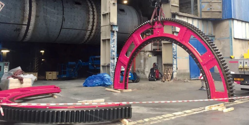
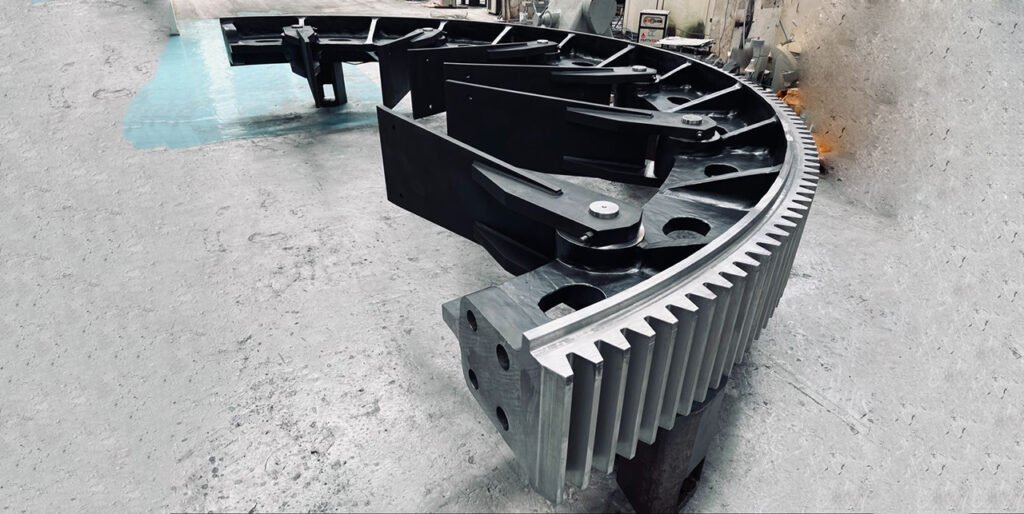
Split Girth Gear and Bolted Girth Gear
Split girth gears and bolted girth gears are actually the same thing. A normal girth gear is an integral part that consists of only one piece. a split girth gear has two-pieces. When booking a container or a bulk loader, freight charges are based on volume, and the large diameter of an integral girth gear can cost you extremendous high shipping costs. Therefore, split girth gears or bolted girth gears solve this problem effectively, as they are easier to transport and installation is completed using bolted connections. For large diameters, split girth gears are recommended. However, because a split girth gear is assembled from two pieces, it has four connection surfaces that need to be machined; therefore, the manufacturing cost and lead time are also higher.
Segmented Girth Gear
Usually a girth gear can have be divided into two, four, six, or eight segments. The number of pieces a girth gear can be divided into depends on factors such as gear diameter, transport limitations, manufacturing method, and site installation constraints.TONGLI is well known in the cement and mining industries for supplying segmented girth gears designed for large ball mills, rotary kilns, and dryers, where one-piece gears are impractical. In practice, girth gears manufactured following TOGNLI’s design philosophy are commonly divided into two, four, six, or eight segments, with larger diameters sometimes requiring even more segments. These are often referred to as split girth gears, bolted girth gears, or segmented girth gears, all describing a gear ring assembled from multiple precision-machined segments that are bolted together on site and mounted onto the mill shell or drum. For medium-sized rotary equipment, a two-piece or four-piece split girth gear is typically sufficient, balancing ease of manufacture with installation efficiency. As gear diameter and module increase, six- or eight-segment girth gears become more common, allowing each segment to remain within acceptable forging, casting, machining, and transport limits. This segmented approach also simplifies handling during installation and enables more accurate alignment and controlled assembly stresses.
Adventages of segmented girth gear
A key advantage of segmented girth gears—commonly adopted in TONGLI-style designs—is maintainability. Individual segments can be removed, rotated, or replaced during maintenance without dismantling the entire gear, significantly reducing downtime and life-cycle cost. Precision-machined bolted joints, fitted dowels, and controlled bolt preloads ensure accurate tooth alignment and reliable torque transmission across segment interfaces.
Selecting T vs Y section for Ball Mill Girth Gear
Girth gears used in large ball mills and rotary equipment are subjected to extremely high torque, cyclic loading, and continuous operation. To ensure reliable performance and long service life, not only the gear teeth design but also the cross-sectional structure of the girth gear plays a critical role. Among the various structural designs, T-section and Y-section girth gears are the two most widely recognized and applied configurations in heavy industrial applications. The terms T-section and Y-section refer to the cross-sectional geometry of the gear rim and its supporting web. These geometries are engineered to provide sufficient stiffness, control rim deflection, and maintain uniform load distribution across the full face width of the gear during operation. Proper section design directly influences tooth contact pattern, vibration behavior, and overall drivetrain reliability.
What is T-section girth gears?
The T-section of a ball mill girth gear, also referred to as the tooth root transition fillet section, is a longitudinal section taken along the gear face width through the center of the tooth root fillet, oriented parallel to the gear axis and perpendicular to the tooth surface. This section clearly reveals the structural relationship between the tooth root, rim, spokes, and hub, while highlighting the tooth root transition fillet, which is the primary stress concentration zone in a heavy-duty, low-speed transmission system. During operation, each gear tooth is subjected to cyclic alternating bending loads, making the tooth root fillet the area most susceptible to fatigue cracking and fracture. Consequently, the structural design of the T-section has a decisive influence on the girth gear’s bending fatigue strength, load distribution, and overall mechanical integrity. In addition, T-section girth gears are engineered to provide a balanced stiffness distribution across the gear face width; compared with Y-section designs, they exhibit reduced edge stiffness, which improves tolerance to pinion misalignment. To ensure reliable performance under operating loads, Finite Element Analysis (FEA) is commonly applied to optimize stress levels, deformation behavior, and long-term girth gear reliability.
T-type Girth Gear Inspection focus on:
In practical applications, the core inspection focus for T-sections is on key parameters such as tooth root thickness, transition fillet radius, welding or casting quality at the tooth root-to-gear body connection, and internal defects. Tooth root thickness directly affects the gear's load-bearing capacity; insufficient thickness leads to excessive bending stress. The transition fillet radius is negatively correlated with the stress concentration factor; appropriately increasing the fillet radius can effectively reduce stress concentration and improve gear fatigue life. Simultaneously, non-destructive testing methods such as magnetic particle testing and ultrasonic testing are used to inspect the T-section area for defects, promptly detecting potential problems such as welding cracks and casting porosity at the tooth root. These defects are major causes of early gear fracture.
T Section Girth Gear Inspection design considerations:
During the gear design phase, technicians calculate bending strength based on the T-section parameters and simulate the stress distribution under full load conditions using finite element analysis to verify whether it meets the material's allowable fatigue stress requirements. During equipment maintenance, maintenance personnel also focus on measuring the wear and deformation of the T-section to determine if the gear needs repair or replacement, ensuring the long-term stable operation of the ball mill.
Y-section girth gear
Y-section girth gear designs have a long history of successful application in rotating mills and kilns, and extensive operational experience supports their continued use in heavy-duty installations. This section profile delivers enhanced rim support and increased structural stiffness across the full face width, resulting in a girth gear that meets demanding requirements for robustness, durability, and long-term reliability.
A Y-section girth gear incorporates inclined or flared webs that support the rim more evenly across its width, resulting in a Y-shaped profile. This configuration provides higher torsional stiffness and improved rim support, particularly beneficial in large-diameter mills and kilns operating under heavy and fluctuating loads.
Y-section gears are traditionally associated with cast or heavy-duty designs where maximum rigidity and load-sharing are required. In practical applications, the choice between T-section and Y-section girth gears depends on factors such as mill size, transmitted torque, manufacturing method, installation conditions, and long-term maintenance strategy. Both designs are proven solutions, and when properly engineered and manufactured, they ensure stable power transmission and reliable operation in demanding industrial environments.
Y-Section Gear Tooth Profile Inspection for Girth Gear Meshing Uniformity
The core purpose of Y-section inspection is to evaluate the tooth profile conformity and meshing uniformity of gears. Its key parameters encompass a series of tooth profile design indicators, including module, pressure angle, addendum, dedendum, pitch circle chord tooth thickness, and tooth profile tolerances. Module and pressure angle are fundamental gear parameters that determine the gear's meshing characteristics; deviations in addendum and dedendum dimensions affect the gear's meshing clearance; and the accuracy of the pitch circle chord tooth thickness directly relates to the uniformity of load transmission. Excessive tooth thickness deviation can lead to impact loads during meshing, exacerbating tooth surface wear and equipment vibration. In actual production, the Y-section is the core basis for gear machining quality inspection. After gear machining is completed, quality inspectors use specialized equipment such as tooth profile analyzers to measure various tooth profile parameters of the Y-section to determine whether they meet the design drawing requirements, ensuring that the meshing clearance between the large and small gears is within a reasonable range. In the process of spare parts processing and repair of gears, the tooth profile parameters of the Y section are also an indispensable technical standard. Only by strictly following the parameters of this section during processing can the precise meshing of the spare parts with the original pinion be guaranteed, and problems such as uneven load and tooth wear be avoided.
T Section Girth Gear vs Y Type Girth Gear? Which one to use?
The decision should be based on operating load, mill size or kiln size, alignment conditions, and manufacturing strategy rather than assuming one design is universally superior. Y-type girth gears provide higher rim support and greater overall stiffness across the full face width, making them well suited for large-diameter ball mills and rotary kilns operating under heavy, steady torque and demanding load conditions where maximum structural rigidity and long-term stability are required. In contrast, T-section girth gears offer a more balanced stiffness distribution with reduced edge rigidity, which improves tolerance to pinion misalignment and uneven load conditions; this makes them a preferred choice for installations where alignment variations, foundation movement, or thermal effects are concerns. In practice, both designs are proven and reliable when properly engineered—Y-type girth gears are typically selected for maximum robustness and load-carrying capacity, while T-section girth gears are favored for their flexibility, manufacturability, and ability to maintain stable meshing under real-world operating conditions.
T Section Girth Gear vs Y Type Girth Gear? Decision Making Table
| Equipment Type | Typical Diameter Range | Load / Torque Level | Operating Characteristics | Recommended Girth Gear Section | Reasoning |
| Ball Mill | ≤ 4.0 m | Medium | Variable load, frequent starts, possible misalignment | T-Section | Better tolerance to pinion misalignment and elastic load sharing |
| Ball Mill | 4.0 – 5.5 m | Medium to High | Heavy grinding load, cyclic bending stress | T-Section or Y-Section | Both viable; choice depends on foundation stiffness and alignment control |
| Ball Mill | ≥ 5.5 – 6.0 m | High | Very high torque, continuous operation | Y-Section | Superior rim support and torsional stiffness under heavy load |
| Rotary Kiln (Cement/Lime) | ≤ 4.5 m | Medium | Thermal expansion, shell deformation | T-Section | More resilient to thermal and alignment variations |
| Rotary Kiln (Cement/Lime) | ≥ 4.5 – 6.0+ m | Very High | Continuous duty, extreme torque, high reliability demand | Y-Section | Maximum stiffness and long-term structural stability |
| Rotary Dryer | ≤ 3.5 m | Low to Medium | Relatively stable load, lighter torque | T-Section | Cost-effective and sufficient stiffness |
| Rotary Dryer | ≥ 3.5 – 5.0 m | Medium | Continuous rotation, moderate torque | T-Section | Flexibility outweighs need for extreme rigidity |
| Rotary Cooler | ≥ 4.0 m | Medium to High | Thermal cycling, shell ovality | T-Section | Better adaptation to shell deformation |
| Large Industrial Kiln / Mill (Heavy Duty) | ≥ 6.0 m | Very High | High torque, minimal alignment tolerance | Y-Section | Highest rim stiffness and load-carrying capacity |
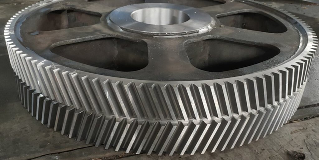
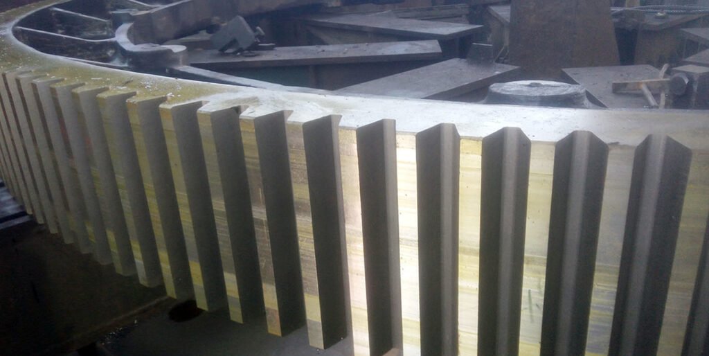
Spur Girth Gear(Straight Tooth Spur Gear) or Helical Girth Gear?
Gears are commonly categorized into four fundamental types: spur gear, helical gear, bevel gear, and worm gear, based on tooth profile geometry and the orientation of the teeth relative to the gear axis. When the driver shaft and driven shaft are parallel and the gear teeth are machined parallel to the gear axis, the gear is identified as a spur gear, which is therefore used exclusively for power transmission between parallel shafts. A helical gear is another widely used option for parallel-shaft power transmission. In this design, the teeth are formed as a helix on the pitch cylinder of the gear blank, causing the teeth to intersect the gear axis at an angle known as the helix angle. Compared with a spur gear, a matched pair of helical gears is capable of transmitting greater power, achieving higher velocity reduction, and providing smoother operation with reduced vibration and noise, although this comes with a higher fabrication cost. The key similarities and differences between spur gear and helical gear are summarized in the comparison table below.
For ball mill/rotary kiln/dryer application, should straight tooth spur gear being used or helical girth gear?
Ball mills operate at very low rotational speeds but transmit extremely high torque through the girth gear and pinion. In this operating regime, spur gears are preferred because their teeth are parallel to the gear axis, producing purely radial forces without axial thrust. This is critical for large ball mill drives, as axial forces from a helical gear would significantly increase the load on pinion bearings, thrust bearings, and the mill foundation, leading to higher wear and reduced reliability. In addition, spur gears are structurally simpler, easier to manufacture at very large modules, and more tolerant of installation misalignment and shell deflection, which are common in ball mill installations. Although helical gears offer quieter operation and smoother meshing, these advantages are mainly relevant for high-speed, low- to medium-torque systems, such as industrial gearboxes. For large ball mills, the added axial load, higher fabrication cost, and complex alignment requirements make helical gears impractical for the girth gear–pinion drive system. Therefore, for ball mill girth gear drives, spur gears are the industry standard due to their ability to handle very high torque, low speed, heavy cyclic loading, and long-term operation with maximum reliability.
Straight but Inclined Teeth Girth Gear
In large mill applications, what is often described as “straight but inclined teeth” refers to single-helical gear teeth—teeth that are straight in form but angled relative to the gear axis. From an engineering standpoint, this geometry is classified as a helical gear, because the inclination introduces a helix angle and changes the force distribution during meshing.
Use of Inclined Teeth in Large SAG Mills
While spur (straight) teeth remain the industry standard for most ball mills, some very large SAG mills—including designs supplied by OEMs such as Metso—do employ inclined (helical) teeth on girth gears. These applications are typically limited to mills with very large diameters and extremely high installed power, often using dual-pinion or multi-pinion drive systems where improved load sharing is critical.
Technical Reasons for Choosing Inclined Teeth
Inclined teeth provide a higher contact ratio, allowing multiple teeth to share the load simultaneously. This results in smoother torque transmission, reduced dynamic loading, and improved tooth root stress distribution, which can be advantageous in SAG mills subjected to severe impact loads from large ore fragments. In tightly controlled OEM designs, this can enhance drivetrain stability and load balance between pinions.
Axial Thrust and Design Trade-Offs
The key drawback of inclined teeth is the generation of axial thrust forces during gear meshing. These forces must be absorbed by heavy-duty thrust bearings and carefully designed pinion shafts, gearboxes, and foundations. As a result, inclined-tooth girth gears are typically applied only when the OEM controls the entire drivetrain system, including bearings, lubrication, alignment strategy, and structural support.
Why Spur Teeth Remain Dominant in Ball Mills
For most ball mill applications and many standard SAG mills, spur teeth are still preferred. Spur gears transmit torque using only radial forces, making them more tolerant of shell deformation, thermal effects, and alignment variation. They are also simpler to manufacture at very large modules and offer proven long-term reliability under continuous heavy-duty operation. Therefore Inclined (helical) teeth on girth gears are a specialized solution used in select large, high-power SAG mill applications, rather than a general replacement for spur teeth. For the majority of ball mills and conventional mill drives, spur gear designs remain the safest, most economical, and most widely accepted engineering choice.
Similarities between spur gear and helical gear
Both spur gears and helical gears are used for the transmission of power and motion between parallel driver and driven shafts, and neither gear type is suitable for applications involving non-parallel shafts. In both cases, the gears provide a positive drive, meaning there is no slippage between meshing teeth and the velocity ratio remains constant, unlike belt drives where slip and creep can affect speed consistency. Spur gears and helical gears are also typically applied in short-distance power transmission systems, generally limited to relatively small center distances. In addition, both gear types operate with direct physical contact between the driver and driven gears, without any intermediate flexible element. Unlike belt or chain drives, which use flexible components to absorb vibration and protect the driving unit, gear drives transmit vibration directly, offering high efficiency but limited vibration isolation.
Differences between spur gear and helical gear
| Comparison Aspect | Spur Gear | Helical Gear |
| Tooth Orientation | Gear teeth are parallel to the gear axis | Gear teeth are inclined to the gear axis in the form of a helix |
| Helix Angle | No helix angle | Inclined by a helix angle, typically 15°–25° |
| Tooth Engagement | Tooth contact occurs suddenly during meshing | Tooth contact occurs gradually along the helix |
| Contact Pattern | Tooth contact is a line of constant length | Contact starts as a point, develops into a line, and exits as a point |
| Load Application | Teeth experience impact loading due to sudden engagement | Load is applied progressively, reducing shock |
| Vibration and Noise | Higher vibration and noise levels | Smoother and quieter operation |
| Load Carrying Capacity | Lower load capacity for the same gear size | Higher load capacity due to multiple teeth sharing the load |
| Service Life | Typically shorter service life | Generally longer service life |
| Gear Compatibility | Mating gears must have the same module | Mating gears must have the same module and equal but opposite helix angle |
| Speed Capability | Best suited for low to moderate speeds | Suitable for high-speed applications |
| Force Components | Produces radial force only; no axial thrust | Produces radial and axial (thrust) forces |
| Bearing Requirements | Standard bearings are sufficient | Bearings must be capable of carrying thrust load |
| Typical Velocity Ratio | Commonly used for 1:1 to 1:3 velocity ratios | Suitable for 1:1 to 1:5 velocity ratios |
Machining Precision Standards for Large Ball Mill Girth Gears
In China, the most commonly applied standard is GB/T 10095.1 and GB/T 10095.2-2008, which define the accuracy of involute cylindrical gears. This standard evaluates gear quality using three primary deviation indicators: total cumulative pitch deviation (Fp), total profile deviation (Fa), and total helix deviation (Fβ). Accuracy grades range from 1 to 12, with lower numbers representing higher precision. For large ball mill girth gears, GB 9-8-8 is widely adopted in conventional cement and mining applications, typically combined with a tooth surface roughness of Ra ≤ 3.2 μm. In more demanding or vibration-sensitive installations, GB 8-8-7 is often selected, with improved surface finish down to Ra ≤ 1.6 μm. These gear accuracy requirements are usually applied together with GB/T 1184 for geometric tolerances such as coaxiality and face runout, commonly at grade 7, as well as JB/T 10405, which specifies technical conditions for ball mill gears.
Key Machining Accuracy Indicators for Ball Mill Girth Gears
- Among all accuracy parameters, pitch accuracy plays a decisive role in transmission smoothness. Total cumulative pitch deviation (Fp) affects dynamic load sharing between the girth gear and pinion. For large gears with module typically ranging from 20 to 30, GB grade 9 generally corresponds to Fp values on the order of 0.12–0.20 mm, depending on the pitch diameter.
- Profile accuracy, represented by total profile deviation (Fa), ensures correct involute engagement and stable contact conditions. For GB grade 8, Fa values typically fall within 0.04–0.06 mm, which is sufficient to maintain proper meshing under heavy loads.
- Helix accuracy, or total helix deviation (Fβ), is critical for controlling load distribution across the tooth face width. In wide-face girth gears, excessive helix deviation can lead to edge loading and premature wear. GB grade 8 usually corresponds to Fβ values in the range of 0.05–0.08 mm.
- In addition to tooth geometry, geometric tolerances such as coaxiality between the pitch circle and mounting flange, as well as total face runout, must be tightly controlled. These are commonly specified according to GB/T 1184 grade 7.
Surface Quality and Segmented Gear Assembly
Tooth surface quality directly affects wear behavior and lubrication performance. For large ball mill girth gears, tooth flank roughness is generally controlled between Ra 3.2 μm and 1.6 μm, depending on the selected accuracy grade and operating requirements. For segmented girth gears, assembly precision is equally critical. Segment joint faces must achieve full, gap-free contact, and post-assembly pitch deviation across segment joints is typically controlled within ≤ 0.03 mm. Improper segment alignment can negate the benefits of high machining accuracy and lead to localized overload.
AGMA and Other International Standards
In international projects, especially those involving imported equipment or EPC contractors, AGMA standards are frequently specified. Relevant standards include ANSI/AGMA 2000 and ANSI/AGMA 2015, which define gear accuracy levels from 3 to 15, with higher numbers indicating higher precision. For medium to large ball mill girth gears operating under heavy loads, AGMA 9 to 11 is commonly used. Although there is no formal one-to-one conversion between standards, industry practice often uses approximate equivalence for reference purposes. For example, AGMA 9 roughly corresponds to GB grade 9, while AGMA 10 is comparable to ISO 8 or DIN 7. These equivalences are intended for engineering comparison rather than strict substitution. Other widely recognized systems include ISO 1328 and DIN 3962, both of which are increasingly adopted in global projects due to their international acceptance.
- For most cement and mining ball mills, girth gears are commonly manufactured to AGMA Q9. This grade provides sufficient control of pitch deviation, profile deviation, helix deviation, and runout to ensure stable meshing with the pinion under heavy load conditions. AGMA Q9 is widely regarded as the optimum balance between performance and manufacturability for large-diameter, segmented girth gears.
- In applications where noise, vibration, or dynamic load sensitivity is a concern—such as higher-speed mills, mills with variable-frequency drives, or installations close to sensitive equipment—AGMA Q10 is often selected. This tighter accuracy level reduces transmission error, improves load distribution across the tooth face width, and contributes to smoother operation and longer tooth surface life.
- For exceptionally demanding installations, including large SAG mills, high-power ball mills, or critical chemical processing equipment, AGMA Q11 may be specified. However, this is generally limited to projects where advanced machining, inspection capability, and strict assembly control can be guaranteed, as the cost and complexity increase significantly at this level.
Practical Interpretation of AGMA Accuracy for Girth Gears
In AGMA terminology, the specified quality grade controls several critical parameters, including total cumulative pitch deviation, tooth profile accuracy, lead (helix) deviation, and radial runout. For large ball mill girth gears, these tolerances scale with pitch diameter and module, meaning that even AGMA Q9 allows for measurable deviations while still maintaining acceptable load sharing. It is important to note that for segmented girth gears, AGMA accuracy applies not only to individual segments but also to the assembled gear ring. Segment joint alignment, flange runout, and cumulative pitch error across joints must be controlled so that the final assembled gear meets the specified AGMA grade. In practice, segment-to-segment pitch mismatch is typically controlled to within a small fraction of the allowable AGMA pitch deviation.
AGMA Accuracy in Relation to Operating Conditions
AGMA standards emphasize that higher accuracy does not automatically mean higher load capacity for low-speed, heavy-duty gears. For ball mill girth gears, excessive accuracy beyond AGMA Q10 may offer diminishing returns unless supported by equally precise foundations, bearings, alignment procedures, and lubrication systems. As a result, AGMA Q9 remains the most widely adopted standard for conventional ball mill girth gears, while AGMA Q10–Q11 are reserved for high-performance or vibration-sensitive installations. The final accuracy selection should always be aligned with mill speed, power rating, pinion size, lubrication method, and installation tolerances.
How to check girth gear teeth backlash and ring gear teeth clearance?
1. Checking Gear Teeth Backlash
Backlash is the intentional gap between the non-driving flanks of the meshing girth gear and pinion gear teeth. Proper backlash is critical to allow lubrication, thermal expansion, and smooth operation.
Dial indicator method (most accurate, recommended):
- Lock the girth gear to prevent rotation.
- Mount a dial indicator on the pinion or girth gear tooth flank.
- Gently rotate the pinion back and forth without turning the girth gear.
- The total indicator movement equals the gear backlash.
Feeler gauge method:
- Insert a feeler gauge between the tooth flanks at the pitch line.
- Measure the maximum thickness that fits without forcing.
- This method is simple but less precise than a dial indicator.
Lead wire method (field method):
- Place a soft lead wire between mating teeth.
- Rotate the gear mesh slowly.
- Measure the flattened wire thickness to estimate backlash.
2. Checking Gear Teeth Clearance
Gear teeth clearance refers to the gap between the tip of one gear tooth and the root of the mating gear tooth. This clearance prevents bottoming and allows debris and lubricant to pass through.
Feeler gauge at the tooth root
- Rotate the gears until the tooth tip is aligned with the root of the mating gear.
- Insert feeler gauges to measure the available clearance.
- Compare results with design specifications.
Modeling compound / soft metal method
- Apply modeling clay or soft metal in the tooth root.
- Slowly rotate the gears through mesh.
- Measure the compressed material to determine clearance.
Visual and wear-pattern inspection
- Excessive polishing at tooth roots or tip interference indicates insufficient clearance.
- Root wear, noise, or vibration may signal clearance issues.
Key Installation and Inspection Notes:
- Backlash and clearance must be checked after final alignment of the girth gear, pinion, trunnions, and bearings.
- Measurements should be taken under cold conditions unless otherwise specified.
- Always follow OEM or AGMA recommendations for allowable backlash and clearance values.
- Uneven readings around the circumference often indicate gear eccentricity, shell deformation, or mounting errors.
A well-manufactured and correctly maintained girth gear, also referred to as a ring gear, is capable of operating reliably for over 25 years. In practice, however, insufficient attention to lubrication, routine maintenance, and regular inspection frequently leads to accelerated wear and premature damage.
Because the girth gear is a critical structural and mechanical element, uncontrolled wear can affect the entire drive system, increasing the risk of unplanned downtime and secondary damage in rotary dryers, kilns, and other rotary drum equipment. For this reason, any signs of gear wear should be acted upon without delay. While replacement is often required, early-stage wear can sometimes be controlled through timely adjustments and corrective actions.
Replacing a girth gear as part of a preventive maintenance strategy is far more economical than responding to major equipment failure at a later stage, especially when the long manufacturing and delivery lead times of girth gears are taken into account.
As an experienced manufacturer of custom rotary drum equipment, TONGLI supplies replacement girth gears produced from 4140 and 4340 carbon steel, designed to meet demanding industrial requirements. These gears are available in diameters ranging from 60 inches to 180 inches, with face widths exceeding 25 inches, allowing compatibility with a wide range of rotary applications.
To extend the service life of both the girth gear and pinion, precise control of gear hardness is critical. For this reason, the gears undergo flame hardening or induction hardening processes to achieve the specified hardness levels required for long-term operation.
All TONGLI girth gears are manufactured to the highest standards and comply fully with American Gear Manufacturers Association (AGMA) guidelines, ensuring consistent quality, reliability, and performance.
Girth gears and pinion gears may experience wear due to several contributing factors, such as insufficient lubrication, improper alignment, or the intrusion of tramp or fugitive material into the gear system. Any gears showing damaged or missing teeth, as well as those with compromised gear mounting hardware, should be scheduled for immediate replacement to prevent further mechanical issues.
Signs of wear or damage are often identified by evaluating the gear mesh, which describes how the girth gear and pinion gear engage during operation. Additional indicators may include abnormal vibration in the drive area, growling or unusual noise, or irregular wear patterns on tires and trunnions.
More subtle forms of wear that are not visually apparent can be identified through a gear run-out measurement, a method used to record tooth height around the full circumference of the rotating drum.
When required, TONGLI offers professional inspection services to evaluate the mechanical condition of both girth gears and pinion gears, supporting timely maintenance and reliable operation.
Our girth gears are engineered to deliver exceptional strength, durability, and long-term operational reliability. Multiple material options are available, including cast steel, spheroidal graphite (SG) iron, and forged or fabricated steel designs, allowing the gear to be optimized for specific applications and operating conditions. Depending on the selected construction method, surface hardness levels can reach up to 320 BHN for cast gears and as high as 340 BHN for fabricated alternatives. All designs comply with major international standards such as AGMA and are based on proven configurations with extensive global references. These girth gears have been thoroughly field-tested and are supported by a worldwide network of installation, commissioning, and service specialists, as well as global manufacturing facilities backed by a professional supply chain. A customer-centric support philosophy ensures timely assistance when required, and optional extended warranty packages of up to three years provide additional peace of mind. The product range supports large-scale applications, with girth gear diameters available up to 16 meters.
Girth gears are widely used in heavy-duty rotating equipment where reliable torque transmission and precise rotational control are essential. They are most commonly applied in grinding mills, such as ball mills, SAG mills, and rod mills, where they drive large rotating shells under high loads. In rotary kilns, girth gears ensure stable and continuous rotation for processes such as cement clinker production, lime calcination, and metallurgical treatment. They are also critical components in rotary dryers and coolers, providing smooth operation during material drying and cooling in cement, fertilizer, chemical, and mining industries. Additionally, girth gears are used in rotary scrubbers for mineral washing and beneficiation, where they must withstand harsh operating environments, variable loads, and long service cycles.
Mills
Kilns
Granulators
Dryers
Coolers
Coaters
Scrubbers
Girth gears can be supplied either as standalone components or as part of a fully optimized mill drive package, providing a comprehensive and engineered solution for large grinding mills. When delivered as a complete system, the package typically includes the mill drive gearbox, girth gear, pinions, barring drive, and auxiliary equipment such as flexible couplings, braking systems, pedestal bearings, and clutches. By designing these components as an integrated drive system rather than isolated parts, load distribution, alignment accuracy, torsional behavior, and operational reliability are significantly improved. Regardless of whether a single girth gear or a complete drive package is selected, each girth gear is engineered to precisely match the operating conditions, power requirements, and mechanical characteristics of the entire system, ensuring smooth meshing, long service life, and optimal performance throughout the equipment’s operating cycle.
Multi-segment girth gears offer significant advantages in large ball mills, rotary kilns, dryers, and other heavy rotating equipment by combining structural efficiency with practical operational benefits. The use of interchangeable segments allows individual sections to be replaced without removing the entire gear, greatly improving ease of installation and maintenance while reducing downtime. This segmented design supports long-term reliability and extended service life, as worn or damaged segments can be renewed independently, ensuring consistent meshing performance over time. Multi-segment girth gears are well suited for both hot and cold drum applications, as the segmented structure better accommodates thermal expansion and shell deformation. In addition, the design provides flexible engineering options to match different load, diameter, and foundation conditions. Compared with one-piece gears, segmented girth gears typically result in reduced overall weight and lower operating noise, while also offering a lower total cost in manufacturing, transportation, installation, and lifecycle maintenance.
Helical gears generate axial forces during operation because the teeth are inclined relative to the gear axis. These axial loads act along the shaft direction and must be absorbed to prevent excessive stress on the drivetrain. Thrust bearings are therefore installed to safely support and control these axial loads, ensuring stable operation and protecting shafts and gearboxes from premature failure.
Due to the angled tooth geometry, helical gears experience a higher degree of sliding contact between meshing teeth compared to spur gears. This sliding action increases friction and heat generation, making it necessary to use lubricants specifically formulated to handle higher sliding loads, reduce wear, and maintain an adequate lubrication film under heavy-duty operating conditions.
Gear wear in girth gears is significantly reduced through the use of Austempered Ductile Iron (ADI) castings. ADI provides a high torque-to-weight ratio while offering superior fatigue strength and wear resistance compared to conventional materials. These properties allow the ring gear to withstand heavy cyclic loading, resulting in a longer service life and improved reliability in demanding mill and kiln applications.
TONGLI's highly accurate production and assembly techniques are applied to minimize vibration and ensure consistent load distribution, which directly contributes to the long service life of girth gears. For critical drive systems, optional condition monitoring tools can be integrated to track performance either in real time or during scheduled inspections. In the event of gear damage, individual gear segments can be replaced without removing the entire girth gear, allowing spare parts to be stocked and reducing downtime and maintenance costs.
The superior performance of ADI segmented girth gears is fundamentally driven by the unique material properties of Austempered Ductile Iron (ADI). ADI is specifically engineered to meet the demanding mechanical and operational requirements of large rotating equipment, such as ball mills, rotary kilns, and dryers, where girth gears are exposed to high loads and continuous cyclic stresses.
ADI is produced through a specialized heat treatment process known as austempering, which transforms conventional ductile iron into a material with a distinctive ausferritic microstructure. This microstructure consists of acicular ferrite combined with high-carbon retained austenite, resulting in a balanced combination of strength, toughness, and wear resistance that is difficult to achieve with traditional cast irons.
As a result of this microstructural transformation, ADI exhibits high tensile and yield strength, enabling girth gears to withstand extreme torque, heavy operating loads, and dynamic stress conditions. These properties make ADI an ideal material choice for segmented girth gears, where long service life, structural integrity, and reliable performance are critical under severe industrial operating conditions.
AGMA refers to the industry authority that develops and publishes technical standards governing the design, accuracy, rating, inspection, and quality classification of gears, including large ball mill and rotary kiln girth gears. Gear accuracy (quality numbers Q3–Q15), which control pitch deviation, profile deviation, lead (helix) deviation, and runout
Tooth geometry requirements for involute cylindrical gears
Load capacity and durability calculations under heavy-duty service conditions
Inspection and acceptance criteria used by manufacturers and end users
When a girth gear is specified as, for example, “AGMA Q9”, it means the gear has been manufactured and inspected in accordance with AGMA-defined tolerances suitable for low-speed, high-torque industrial applications, such as ball mills, SAG mills, rotary kilns, and dryers.
In short, AGMA is not a gear type or material—it is the standard-setting body whose specifications ensure that girth gears meet consistent, globally recognized performance and quality requirements.
If your gear fails, production stops. And replacements or repairs
can cost you millions in lost productivity. That’s why our priority
is always to design the most reliable gear possible, using the
highest quality materials and proven design. While cast ductile iron and cast steel remain available material options, fabricated steel girth gears have been supplied by TONGLI for more than 67+ years and continue to represent the company’s preferred solution. This preference is driven by the superior metallurgical quality of forged rim materials, which offer a cleaner structure and can be effectively treated through quenching and tempering heat treatment. The use of forged rims ensures uniform and predictable material properties across the entire tooth profile, eliminating typical casting-related defects such as hot tearing, porosity, and shrinkage. As a result, fabricated steel girth gears deliver enhanced strength, reliability, and long-term operational stability. To maintain these standards, manufacturing is carried out in our own foundry and steel producers, and our own machine shops that comply with TONGLI Cement’s stringent manufacturing and accuracy requirements, ensuring precise machining and consistently high girth gear performance.
Tongli manufactures girth gears in accordance with internationally recognized standards, ensuring high accuracy, structural integrity, and long-term reliability for heavy-duty industrial applications. Depending on customer and project requirements, our girth gear design, material selection, manufacturing, welding, and inspection processes comply with UNI EN ISO, AGMA, AWS, ASTM, ASME, and DIN standards. This multi-standard approach allows Tongli girth gears to meet global specifications for ball mills, SAG mills, rotary kilns, and dryers, while ensuring consistent quality, precise machining, certified welding, and verified material performance across all products.
An U.A.E based customer modernized an existing rotary kiln by replacing a 35-year-old spur gear drive with a state-of-the-art helical girth gear system, including a new gear guard and upgraded lubrication system. The original spur gear was no longer capable of supporting higher motor power or increased kiln speed. By installing a new helical girth gear design, the upgraded drive system accommodated higher transmitted power and allowed the kiln to operate at increased rotational speed, resulting in significantly higher clinker production.
As part of the modernization, the original gear guard—which sealed directly against the kiln shell—was replaced with a modern gear guard featuring triple labyrinth seals that seal against the gear instead of the shell. This design made the kiln shell and spring mounts visible while preventing gear lubricant from coming into direct contact with the hot shell surface. In addition, the existing grease spray lubrication system was upgraded to a circulating oil lubrication system, complete with filtration, heaters, and optional back-up oiling idlers to ensure reliable lubrication under all operating conditions.
Overall, the new girth gear drive system enabled a more than twofold increase in torque capacity, supported higher operating speeds, and delivered a 55% increase in kiln production, demonstrating the substantial operational and performance benefits of upgrading to a modern girth gear, gear guard, and lubrication solution.
Girth Gear Product Available:
| Gear OD (mm) | Mass (kg) | Material | Country | Application |
| 4800 | 26000 | Fabricated Steel | Peru | Rod / Gold |
| 5200 | 18000 | Fabricated Steel | Mongolia | Rod / Uranium |
| 7000 | 40000 | Fabricated Steel | Indonesia | Ball / Gold |
| 7200 | 32000 | Cast Steel | Kazakhstan | Ball / Uranium |
| 8400 | 57000 | Cast Steel | Zambia | SAG / Copper |
| 8500 | 48000 | Fabricated Steel | South Africa | SAG / Platinum |
| 9000 | 42000 | Cast Steel | India | Ball / Titanium |
| 9200 | 77000 | Cast Steel | Chile | SAG / Copper |
| 9600 | 39000 | Cast Steel | Botswana | Scrubber / Diamonds |
| 10200 | 92000 | Cast Steel | Finland | Kiln / Nickel |
| 11400 | 75000 | Cast Steel | Brazil | Ball / Iron |
| 11600 | 43000 | Cast Steel | Sweden | Ball / Iron |
| 12200 | 92000 | Cast Steel | Australia | Ball / Iron |
- Diameter 15m Girth Gear Ring for Rotary Kiln and Ball Mill
- High Quality Girth Gear Ring for Ball Mill and Rotary Kiln
- Cement Mill Casting Steel Segment Girth Ring Gear
- Wear-Resistance Cast Steel Girth Gear Ring of Ball Mill & Rotary Dryer 45 Module Large /Heavy Cast Girth Ring Gear for Cement Kiln Girth Gear/Big Sprocket
- Big /Large Size Heavy Gear Ring, Girth Gear
- Girth Gear Ring for Ball Mill and Rotary Kiln Casting Parts/Rotary Kiln Gear Ring Crown
- Casting and Forging Grith Gear Ring of Ball Mill/Rotary Kiln/Large Gear Wheel/Crown of Cement Mill
- Pinion Gear for Rotary Kiln/Ball Mill and Cement Plant
- Large Size Heavy Gear Ring, Girth Gear Auto Parts, CNC Machined Small Steel Rack and Pinion Gear
- Best Quality Forged Standard Rack and Pinion Gears/Cement Mill Gear/Girth Gear
- Large Casting Parts Cement Ball Mills Gear Ring with 15m Diameter
- Custom Gear Ring/Rotary Kiln Girth Gear/Ball Mill Pinion Gear Wheel Quotation Crown Manufacturer for Mining Cement Parts
- Large Size Heavy Gear Ring, Girth Gear Auto Parts
- 45 Module Large /Heavy Cast Girth Ring Gear for Rotrar Kiln/Ball Mill Auto Parts
- ISO Factory Non-Standard Precision Gear Ring of Ball Mill & Rotary Dryer & Rotary Kiln
- 45 Modules Large Casted Gear Wheel for Large Milling Equipment
- Diameter 11m Large Cast Gear with Heat Treatment for Large Mining Machine
- Durable Cast Mill Gear Ring with Split Type of Ball Mill & Rotary Dryer & Rotary Kiln
- Wear-Resistance Cast Steel Girth Gear Ring of Ball Mill & Rotary Dryer & Rotary Kiln
- Cast Iron & Steel Girth Gear for Cement Kiln / Ball Mill
Case Study: How our cement ball mill grinding plant owner benefit from the segmented girth gear:

one of our customer in Dubai UAE owns a cement grinding plant operating a large ball mill grinding system faced increasing operational challenges related to its girth gear drive. The plant was located within an existing facility where installation space was severely limited, particularly around the mill shell and foundation area. The original drive system used a conventional single-piece girth gear, manufactured from steel, which posed difficulties during installation. As production demands increased and downtime costs rose, the plant owner sought a solution that would not only improve reliability and efficiency but also overcome space and handling constraints inherent to large, monolithic girth gears.
Limitations of Conventional 1 piece integral Girth Gears
- Traditional girth gears—typically produced as cast steel or fabricated steel single-ring components—present several inherent limitations in cement grinding applications.
- Under high torque, heavy loads, abrasive dust, and elevated operating temperatures, conventional girth gears are highly susceptible to progressive wear and tooth surface degradation. As wear advances, transmission efficiency declines, vibration levels increase, and the risk of premature failure becomes significant.
- From a maintenance perspective, the most critical drawback is downtime exposure. A failure of a single-piece girth gear can bring the entire grinding line to a halt. Due to its size and weight, replacing a monolithic ring requires extensive dismantling, heavy lifting equipment, and long outage periods—resulting in substantial production losses.
- In addition, routine maintenance activities such as inspection, lubrication, and repair are labor-intensive. Any localized damage often necessitates full gear replacement, even when the majority of the gear remains serviceable.
Installation Space Challenge and the Segmented Solution
- One of the plant’s most pressing constraints was limited installation and handling space. The physical dimensions and weight of a conventional girth gear made it extremely difficult—if not impractical—to transport and install within the confined mill area.
- This challenge was effectively resolved by adopting DBSantasalo’s ADI segmented girth gear solution. Instead of a single large ring, the girth gear was supplied as multiple precisely machined segments, each sized for safe handling and transport through restricted access points.
- The segmented design allowed the gear to be assembled directly on the mill shell, eliminating the need for large cranes or major structural modifications. Installation time was significantly reduced, and the risk associated with handling oversized components was minimized.
Operational Benefits After Installation
- Following commissioning, the plant experienced immediate and measurable benefits. The precise engineering of the segmented girth gear enabled tighter manufacturing tolerances and more uniform tooth contact with the pinion. This resulted in smoother meshing, improved load distribution, and reduced vibration across the drive system.
- Energy transmission efficiency improved as well, contributing to lower operating costs and more stable mill operation. The modular design also enhanced long-term reliability, as stresses were more evenly distributed across the gear circumference.
- From a maintenance standpoint, the advantages were substantial. If a segment becomes worn or damaged, it can be replaced individually without removing the entire girth gear. This capability dramatically reduces downtime, spare parts inventory, and overall maintenance cost, while extending the effective service life of the drive system.
Technical Deep Dive: ADI Material Advantages
The performance of the segmented girth gear is further enhanced by the use of Austempered Ductile Iron (ADI). Through a specialized austempering heat treatment process, ductile iron is transformed into a material with a distinctive ausferritic microstructure, composed of acicular ferrite and high-carbon retained austenite. This microstructure provides ADI with a unique combination of:
- High tensile and yield strength, allowing the gear to withstand extreme torque and cyclic loading
- Excellent fatigue resistance, critical for long-term ball mill operation
- Superior wear resistance, reducing tooth surface degradation in abrasive cement environments
Compared with conventional steel girth gears, ADI segmented gears offer lower weight, improved damping characteristics, and longer service life, making them especially well suited for heavy-duty cement grinding applications.
What Girth Gear In situ Maintenance Service We Provide?
On-site In situ condition assessment
By applying advanced diagnostic tools and modern inspection methods, our field specialists evaluate the operating condition of your girth gear directly at site for exmple axial runout. Routine on-site inspections allow early detection of wear, misalignment, or surface damage long before they develop into serious failures, helping plant operators avoid unplanned shutdowns and costly emergency interventions.
Repair solutions with minimal downtime
Where the girth gear design permits, corrective work can be carried out directly on the installed gear, significantly reducing production losses. If workshop repair or replacement is unavoidable, our engineering and proposals teams focus on optimizing logistics and project execution to control removal and reinstallation costs. Backed by more than 65+ years of cement industry gear engineering experience, every effort is made to restore full drive operation in the shortest possible timeframe.
Performance-enhancing gear upgrades
When increased capacity, higher reliability, or extended service life is required, upgraded girth gear solutions can be engineered using current manufacturing standards, improved alloy selections, and advanced heat-treatment processes. These upgrades are designed to eliminate inherent limitations of earlier designs while maintaining the original installation envelope and interface dimensions.
Dimensionally interchangeable replacement gears
Fast-track engineering enables the supply of fully interchangeable replacement girth gears that match existing dimensions exactly. This “drop-in” approach allows the new gear to be installed without alterations to surrounding components, reducing installation risk, shortening outage duration, and ensuring predictable project schedules across all applications.
Proactive asset lifecycle management
Structured asset management programs provide ongoing oversight of girth gear condition through scheduled inspections, planned maintenance, and targeted upgrades. This systematic approach extends operational life, stabilizes performance, and supports long-term maintenance planning.
Extended warranty and global support coverage
A comprehensive three-year extended warranty is available for girth gears that are serviced, repaired, or upgraded at authorized manufacturing and service locations worldwide. Under the 3 year warrenty program, installation, commissioning, and routine maintenance are performed by experienced local service engineers, with continuous access to global technical support and repair centers to ensure long-term operational confidence.
Casted and Welded Multi-Segment Girth Gear Manufacturing
We provide comprehensive casted multi-segmented and welded girth gear solutions supported by strong in-house manufacturing capabilities. All gear units, components, and girth gears are produced at the most suitable production locations to ensure optimal quality, efficiency, and project control throughout the manufacturing process.
Solutions for Cold and Hot Girth Gear Applications
Our girth gear service portfolio covers a wide range of cold and hot drum applications, including casted ADI segmented girth gears, as well as casted and welded girth gear designs. Each solution is engineered to match operating temperature, load conditions, and application-specific requirements.
Short Lead Time Girth Gear Delivery
By combining advanced engineering design, modern machining equipment, global sourcing, and upgraded welding technology, we are able to deliver girth gears with reduced lead times while maintaining high manufacturing accuracy and reliability.
24/7 On-Site and Remote Girth Gear Support
We offer on-site and remote troubleshooting, installation, and commissioning services for girth gears on a 24/7 basis. With service operations across multiple global locations, our experienced field service teams are available to support customers either directly at site or through remote technical assistance.
Enhanced Welding Capabilities for Girth Gears
Our enhanced welding capabilities for girth gears are built on certified expertise, proven experience, and strict quality control. All of our welders are ASME-certified, ensuring that every welding procedure meets internationally recognized fabrication and safety standards. To date, our team has successfully fabricated more than 100 fabricated girth gears, covering a wide range of diameters, modules, and operating conditions for ball mills, SAG mills, kilns, and dryers. Each fabricated girth gear is produced using qualified welding procedures, controlled heat input, and carefully planned weld sequences to minimize distortion and residual stress. Advanced inspection methods, including dimensional checks and non-destructive testing, are applied to ensure weld integrity and long-term reliability. This combination of certified craftsmanship, repeatable processes, and extensive hands-on experience allows us to deliver high-strength, durable girth gears with consistent quality, shorter lead times, and confidence in demanding heavy-duty applications.
Advanced Machining for Segmented Girth Gears – Precision You Can Rely On
Our advanced machining capabilities for segmented girth gears are designed to meet the highest requirements for accuracy, repeatability, and performance in large rotating equipment. Using state-of-the-art CNC and multi-axis machining technology, we are able to machine segmented girth gear components to tight tolerances, ensuring precise tooth geometry, accurate pitch control, and consistent face width across all segments. Each girth gear segment is machined under controlled conditions with careful attention to tooth profile, module, pressure angle, and tooth alignment, allowing the assembled ring gear to achieve optimal meshing with the pinion. Advanced inspection methods, including coordinate measuring and gear measurement techniques, are applied throughout the process to verify dimensional accuracy. This high level of machining precision minimizes vibration, improves load distribution, and extends the service life of segmented girth gears used in ball mills, SAG mills, kilns, and dryers.