


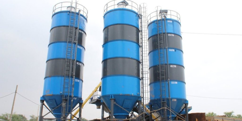
The three main types of cement storage silos are steel silos (steel plate silos), reinforced concrete silos, and hybrid silos (steel-concrete combination silos). The core constraint in concrete production is the continuity of material supply. Any interruption in the cement supply directly leads to construction stoppages, resulting in project delays and financial losses. By utilizing sealed, high-capacity storage combined with controllable, quantitative conveying mechanisms, cement storage silos enable the bulk storage and precise dispensing of loose cement; they represent the standard engineering solution for mitigating issues related to fluctuations in cement supply. Furthermore, serving as a critical interface between the downstream end of the cement production line and the upstream end of the concrete production process, these silos directly impact the operational efficiency of the entire cement supply chain. Currently, the global construction industry is witnessing a trend toward an increased proportion of on-site production, as contractors gradually reduce their reliance on off-site ready-mixed concrete. By replacing bagged cement and off-site mixing operations, on-site cement storage silos can reduce transportation costs by 30% to 50%, eliminate the risk of delivery delays, minimize manual handling requirements, and prevent material spoilage caused by moisture. A cement storage silo is not merely a standalone steel vessel; rather, it constitutes an integrated engineering system encompassing material flow control, safety safeguards, and environmental management. Working in synergy with the clinker conveying, cement grinding, and bulk dispatch systems of the cement production line—as well as downstream batching, mixing, and conveying equipment—it forms a complete, cohesive industrial chain for cement production and application.
Functions and Working Principles of Cement Storage Silos
Core Features
The cement storage silo features a fully sealed steel structure, and its primary functions include:
- Stores powdery construction materials such as cement, fly ash, lime, and slag powder.
- Maintains a dry internal environment to prevent material caking and deterioration.
- Provides a continuous and stable flow of materials to downstream processes.
- Monitors internal material levels in real-time to facilitate inventory management.
- Controls dust emissions during operations to ensure compliance with environmental regulations.
- Prevents abnormal internal pressure fluctuations, thereby safeguarding the structural integrity of the equipment.
- Serves as the terminal buffer unit within a cement production line's bulk dispatch system, balancing the pace of production against that of sales.
Material Flow Mechanism
Cement is pneumatically conveyed from a tanker truck into the silo via a filling pipeline, where it accumulates in the conical lower section of the silo body under the influence of gravity. During the discharge process, a fluidization system injects compressed air into the material bed, causing the powdered material to enter a fluidized state and thereby reducing its internal angle of friction. The material then flows downward along the inner walls of the conical hopper, passes through the discharge outlet into a conveying system, and is transported to a mixing or batching unit. The pneumatic conveying technology employed here operates on principles identical to those used in cement production lines—specifically for material transfer from the clinker silo to the cement mill, and from the cement mill to the bulk storage silo—ensuring that the core equipment is fully interchangeable.
During filling operations, air within the silo is filtered by a top-mounted dust collection unit before being vented; this prevents dust dispersion and guards against over-pressurization within the silo. A material level monitoring system continuously collects real-time data on the material height inside the silo; when the material reaches a preset upper limit, an overflow prevention mechanism is triggered to automatically close the filling pipeline. Conversely, when the material level drops to a preset lower limit, a replenishment alert is issued.
Since cement is typically loaded pneumatically, a significant volume of air becomes entrained within the material, resulting in a loose, aerated state. During storage, this entrained air gradually dissipates, causing the material density to increase from approximately 850 kg/m³ to between 1,200 and 1,300 kg/m³. This change in density must be carefully factored into capacity calculations and equipment design to prevent the silo from becoming overfilled or to avoid discrepancies between the theoretical and actual storage volumes.
Classification System and Technical Characteristics of Cement Storage Silos
The classification of cement storage silos requires a comprehensive consideration of three dimensions: mobility, structural form, and construction method; products falling under different classification dimensions possess distinct technical boundaries and scopes of application.
Classified by Mobility
This classification method is the most widely used standard in engineering practice, directly corresponding to the equipment's usage scenarios and deployment methods.
Fixed Cement Storage Silo
Installed upon a permanent reinforced concrete foundation, this unit is suitable for long-term, stable production environments. Its technical characteristics include: a wide capacity range capable of meeting storage requirements spanning from several hundred to hundreds of thousands of tons; high structural strength, with a designed service life of 20 to 30 years; and compatibility with high-flow conveying systems and efficient dust collection systems. However, it entails rigorous requirements for foundation construction, involves a lengthy installation period, and is a non-mobile piece of equipment. The support legs of standard stationary cement storage silos typically provide a clearance of 3.5 feet beneath the discharge outlet, and are available in three structural designs: non-through, through, and bridge-type configurations.
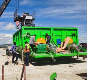
Mobile Cement Storage Silo
Featuring an integrated steel frame and running gear, the unit can be transported in its entirety via a tow vehicle, making it ideal for operational scenarios requiring frequent site relocation. Its technical specifications include: a typical capacity ranging from 30 to 200 tons; installation requires no complex foundation, and certain models utilize a heavy-duty skid base that allows for direct placement on flat, compacted ground; rapid deployment, with installation and commissioning achievable within 1 to 4 hours; a low profile, facilitating passage through areas with road height restrictions; and modular integration capabilities with mobile mixing plants. Note that the axles are designed solely for use in an unloaded state; consequently, the silo must be completely emptied of all materials prior to relocation.
Low-Profile Cement Silo
A specialized variant of the mobile storage silo, this unit is specifically engineered for sites with strict height restrictions. Its key technical features include: an overall height maintained within 13 feet 6 inches; a low center of gravity, ensuring exceptional stability during transport and installation; and full compliance with road transport regulations, thereby eliminating the need for oversized load permits. It is ideally suited for use at urban construction sites, indoor industrial facilities, airport vicinities, and other areas subject to aviation or structural height limitations.
Tilting-Bucket Cement Storage Silo
Representing a distinct variant of the mobile storage silo, this design features a tiltable silo body. Its technical characteristics include: utilizing a hydraulic system to tilt the silo body during discharge, thereby enhancing material flow efficiency; suitability for materials with poor flow characteristics; and the capability for rapid discharge. However, its structure is relatively complex, resulting in higher maintenance costs.
Classified by Structural Form
This classification method primarily affects equipment space utilization and material flow characteristics.
Vertical Cement Storage Silo
It employs a vertical cylindrical structure, increasing storage capacity by maximizing height while simultaneously minimizing its footprint. Its technical characteristics include: a small footprint relative to storage capacity, resulting in high land utilization efficiency; reliance primarily on gravity for material flow, leading to low energy consumption; a significant overall height, rendering it unsuitable for sites with height restrictions; and stringent requirements regarding foundation load-bearing capacity. The structural design principles of this configuration are identical to those of cement silos and clinker silos found in cement production lines, all of which utilize a gravity-flow discharge mechanism.
Horizontal cement storage silos
It features a horizontal cylindrical structure, characterized by a low overall profile and excellent stability. Its technical characteristics include: a relatively large footprint; a reliance on auxiliary fluidization devices to facilitate material flow; ease of transport, allowing for conveyance via standard flatbed trucks; and the ability to be placed directly upon strip foundations or level ground.
Compartmented Cement Storage Silo
By incorporating multiple independent storage compartments within a single silo body, this design enables the simultaneous storage of different types of materials. Its key technical characteristics include: enhanced space utilization; a reduced requirement for equipment; and suitability for production facilities that require a variety of powdered materials. However, it features a relatively complex structure and entails higher manufacturing costs. The capacity range for compartmentalized cement storage silos typically falls between 500 and 1,200 barrels.
Classified by Construction Method
This classification method primarily affects the manufacturing, transportation, and installation costs of the equipment.
Welded Cement Storage Silo
Constructed from steel plates welded into a single, integral structure at the factory, larger units may be welded in sections and subsequently assembled on-site. Its key technical characteristics include: excellent overall airtightness; high structural strength; significant logistical challenges regarding the transport of the monolithic unit, which is constrained by road transport conditions; minimal on-site installation workload; and the inability to be dismantled for relocation. The steel plates used for fully welded cement storage silos typically range in thickness from 3/16 to 1/4 inch, while the top deck is constructed using No. 10 gauge standard steel plate.
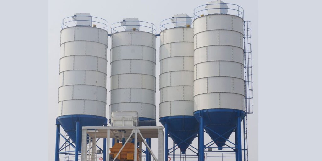
Bolted Cement Storage Silo
It is constructed from standardized, prefabricated steel plates joined together using high-strength bolts. Its technical characteristics include: components can be transported via shipping containers, resulting in low transportation costs; on-site assembly requires no heavy lifting equipment; it can be dismantled and reassembled at a different location, offering a high rate of reusability; its sealing performance is contingent upon the quality of installation; and its capacity can be flexibly adjusted to meet specific requirements.
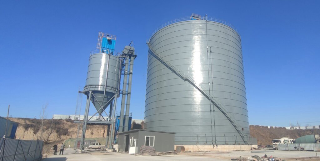
Spiral-Folded Cement Storage Silo
Utilizing specialized on-site equipment, steel strips are continuously cold-formed and coiled to construct a silo body featuring a continuous spiral seam. Its key technical characteristics include: excellent sealing performance; high utilization efficiency of steel materials; and rapid construction—with the construction cycle for a single silo typically controllable within 1 to 2 weeks. It is well-suited for medium-to-large-scale storage requirements, though it is not designed to be dismantled. The storage capacity of spiral-seam cement silos typically ranges from 500 to 100,000 tons, with diameters capable of reaching 20 to 25 meters.
The table presents a comparison of the core technical parameters for different types of cement storage silos.
| Classification Dimension | Specific Type | Capacity Range (Barrels) | Capacity Range (Tons) | Height Range (Meters) | Foundation Form | Installation Cycle | Conveying Capacity (Tons/Hour) |
| Mobility | Fixed | 185-100000+ | 27.75-15000+ | 10-50 | Reinforced Concrete Foundation | 1-6 months | 50-500 |
| Mobility | Circular Portable | 185-1050 | 27.75-157.5 | 8-15 | Leveled Compacted Ground | 1-4 hours | 20-100 |
| Mobility | Low Profile | 200-350 | 30-52.5 | 3.5-4.5 | Leveled Compacted Ground | 1-2 hours | 30-120 |
| Mobility | Dump/Tipping | 200-600 | 30-90 | 6-10 | Leveled Compacted Ground | 2-4 hours | 40-150 |
| Structure Form | Vertical | 185-100000+ | 27.75-15000+ | 10-50 | Reinforced Concrete Foundation | 1-6 months | 50-500 |
| Structure Form | Horizontal | 200-2000 | 30-300 | 3-6 | Concrete Strip Foundation | 1-2 days | 30-150 |
| Structure Form | Compartmentalized | 500-1200 | 75-180 | 10-30 | Reinforced Concrete Foundation | 2-4 months | 30-200 |
| Construction Method | Welded | 185-5000 | 27.75-750 | 8-40 | Reinforced Concrete Foundation | 1-3 months | 30-300 |
| Construction Method | Bolted Assembly | 500-5000 | 75-750 | 10-40 | Reinforced Concrete Foundation | 2-4 weeks | 50-400 |
| Construction Method | Spiral Seamed | 2000-100000+ | 300-15000+ | 15-50 | Reinforced Concrete Foundation | 1-2 weeks | 100-500 |
Capacity Calculation and Engineering Selection Methods
Capacity Measurement Units and Conversions
The capacity of a cement storage silo is typically expressed in units of volume or weight. The industry-standard units of volume are cubic feet and barrels, where one barrel is equivalent to four cubic feet. The units of weight are tons and pounds.
The bulk density of cement varies depending on its physical state:
- Pneumatic Loading:Loose State: 300 lbs/barrel (850 kg/m³)
- Compacted State: 360–390 lbs/barrel (1200–1300 kg/m³)
The densities of different materials also vary.
- Fly Ash: 55 lbs/ft³ (during pneumatic loading); 70 lbs/ft³ (after compaction)
- High-Capacity Mobile Silo: 75 lbs/ft³ (in suspension); 90 lbs/ft³ (compacted)
Capacity calculations must account for density variations across two distinct states to prevent issues such as silo overfilling or insufficient actual storage volume.
Required Capacity Calculation
The required capacity of a cement storage silo should be determined based on the scale of production and material supply conditions. The calculation formula is as follows:
Required Capacity (tons) = Daily Concrete Output (cubic meters) × Cement Consumption per Cubic Meter of Concrete (tons/m³) × (Cement Delivery Cycle + Safety Stock Days)
In this formula, the cement consumption per cubic meter of concrete typically ranges from 300 to 350 kilograms; the specific value is determined by the concrete grade. The cement delivery cycle is determined by local logistics conditions and generally ranges from 1 to 3 days. It is recommended to set the safety stock duration at 3 to 5 days to account for potential delivery delays.
For example, for a construction site producing 100 cubic meters of concrete daily—with a cement consumption of 320 kilograms per cubic meter, a cement delivery cycle of 2 days, and a safety stock duration of 3 days—the required cement storage silo capacity would be:
100 × 0.32 × (2 + 3) = 160 tons
Converted into barrels: 160 tons ÷ 0.136 tons/barrel ≈ 1,176 barrels (based on a standard of 300 pounds per barrel).
For finished-product storage silos supporting a cement production line, capacity calculations must also take into account three additional factors: the hourly output of the cement mill, equipment maintenance cycles, and market sales fluctuations. Such silos are typically designed to accommodate 7 to 15 days' worth of production output.
Four Key Factors for Capacity Selection
Capacity selection must be based on the following four key factors:
- Daily Concrete Output: Determine the daily cement requirement.
- Cement Delivery Cycle: Account for local logistics conditions to determine the lead time for cement delivery.
- Batch Size and Mixer Throughput: Align with the production rhythm.
- Types of Stored Materials: Account for the varying densities of cement, fly ash, lime, or mixed powders.
The Consequences of Inadequate Capacity
- Insufficient Capacity: Leads to production interruptions during replenishment periods and increases the costs associated with urgent deliveries.
- Excessive Capacity: Results in a waste of capital and floor space, and increases the risk of material deterioration due to prolonged storage (cement, when stored in sealed conditions, has a shelf life of 3 to 6 months).
The correct capacity selection should support consistent batching cycles, ensuring that production is not interrupted by replenishment.
Core System Components of a Cement Storage Silo
The cement storage silo consists of seven mutually independent yet collaborative systems, which collectively facilitate the storage, conveyance, and safety management of materials.
Silo Structure System
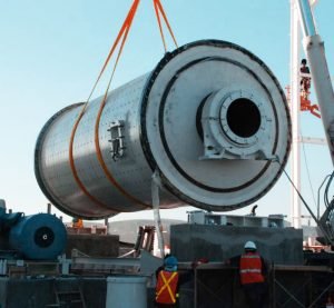
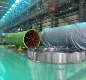
The silo structural system serves as the foundation of the equipment, comprising a cylindrical shell, a conical hopper, and a supporting structure. The cylindrical shell is formed by rolling steel plates, the thickness of which is determined based on the silo's height and capacity.
- 374-606 Barrel: 3/16-inch steel plate sidewalls, 1/4-inch dome
- 837-1069 Barrel: First ring 1/4-inch steel plate, remainder 3/16-inch
The cone angle of the hopper is typically designed at 60 degrees to ensure that materials flow naturally under the force of gravity. The supporting structure varies depending on the equipment type: stationary units utilize reinforced concrete legs, typically providing a clearance of 3.5 feet beneath the discharge point; mobile units feature a steel chassis and axles, equipped with electric brakes and lighting systems to comply with road transport regulations.
Conveying System
The conveying system is responsible for transporting materials from the hopper to downstream production equipment, and primarily takes two forms:
- Screw Conveyors: Widely adopted, these conveyors feature a diameter range of 7 to 14 inches, with conveying capacity directly proportional to the diameter. Screw conveyors can be equipped with multiple inlets and outlets, and are even capable of blending various materials. The length is determined based on the site layout and equipment spacing. Standard configurations include a high-power gear motor, adjustable ball joints, and robust suspension brackets. This equipment also serves as the standard solution for the short-distance conveying of powdery materials within cement production lines.
- Pneumatic Conveying Systems: Suitable for high-capacity applications, these systems consist of a 60-horsepower blower and a rotary airlock, achieving a maximum output of up to 2,688 cubic feet per hour. The rotary airlock features an 8-vane design, equipped with bolt-on AR steel rotor tips as well as a chrome-plated housing and end plates. The system also includes a silencer, a pre-filter, and a low-pressure air purge system. This technology is identical to the pneumatic conveying technology utilized in the bulk shipping systems of cement production lines.
Fluidization System
The fluidization system is critical for ensuring the smooth flow of powdered materials; it consists of an air compressor, an air storage tank, solenoid valves, and aeration pads. The air compressor features a power range of 5 to 75 horsepower, while the air storage tank has a capacity ranging from 80 to 1,000 gallons. Aeration pads are uniformly distributed along the inner walls of the hopper—typically eight units—and function by injecting low-pressure compressed air to fluidize the material, thereby preventing clumping and bridging.
Fluidization systems are categorized into two types: low-pressure/high-flow and high-pressure; the appropriate type is selected based on the specific characteristics of the material. For materials prone to clumping—such as fly ash—an enhanced fluidization system is required.
Filling System
The filling system serves to connect cement tankers to storage silos, facilitating the pneumatic conveyance of materials. The filling pipeline typically features a diameter of 4 to 5 inches and is fitted with quick-release couplings at its terminus, enabling rapid connection to the cement tanker's discharge line. Some systems are equipped with dual filling pipelines to enhance the filling rate.
The overflow prevention mechanism consists of a high-level sensor and a pneumatic actuator; when the material reaches a predetermined level, the system automatically closes the pinch valve or butterfly valve located on the filling pipeline, thereby preventing overfilling and safeguarding the dust collection system against damage.
Safety and Environmental Protection System
The safety and environmental protection system comprises pressure/vacuum relief valves, dust collectors, level indicators, and emergency stop buttons. The pressure/vacuum relief valves automatically actuate when the internal silo pressure exceeds ±2.5 kPa, thereby equalizing the pressure inside and outside the silo.
The dust collector utilizes either a pulse-jet or bag-type design, featuring a filtration area ranging from 150 to 500 square feet; it effectively captures dust generated during the filling process. The standard configuration includes a 150-square-foot filtration chamber, with a 225-square-foot chamber available as an option. The dust collection technology employed here operates on the same principles as the systems used at the rotary kiln outlet and cement mills within cement production lines.
Level indicators are available in three types—rotary, capacitive, and radar—enabling material height measurement with varying degrees of precision. Non-contact radar or plumb-bob type level indicators provide more accurate inventory data, thereby preventing over-ordering and material spillage.
Control System
The control system facilitates the centralized management and automated control of all equipment, incorporating control panels, automatic/manual selector switches, audible and visual alarm devices, and remote monitoring interfaces. The control panels display the operational status and process parameters of each individual unit. The alarm devices emit audible and visual signals in the event of abnormal material levels, pressure anomalies, or equipment malfunctions.
This advanced control system is equipped with intelligent control units capable of executing automated material flow control, predictive maintenance, and remote data acquisition. Select equipment units feature Variable Frequency Drive (VFD) control, allowing for the adjustment of conveying speeds to meet specific production demands. The system also incorporates overpressure switches for the conveying system, alongside automated flow control functionalities. Utilizing standard communication protocols, the control system can seamlessly exchange data with the DCS of a cement production line or the control system of a concrete batching plant, thereby establishing a fully integrated and automated production chain.
Maintenance and Repair System
The maintenance and inspection system provides safe access for routine equipment checks and upkeep, comprising manholes, ladders, work platforms, and fall protection devices. The manholes, ranging in diameter from 600 to 800 millimeters, are positioned at the upper section of the silo body and the lower section of the hopper to facilitate internal inspections and the removal of accumulated material.
Ladders are categorized into two types: internal and external. Access to the internal ladder is gained through the pressure/vacuum relief valve, while the external ladder is equipped with a safety cage and fall protection devices, ensuring full compliance with occupational health and safety standards. A work platform is situated at the top of the silo body, featuring guardrails and toe boards to facilitate safe operations for maintenance personnel. The equipment is available with a variety of customizable color options.
Engineering Application Scenarios for Cement Storage Silos
Cement storage silos are widely utilized across various fields of construction engineering and industrial production, with different types of equipment corresponding to specific application scenarios.
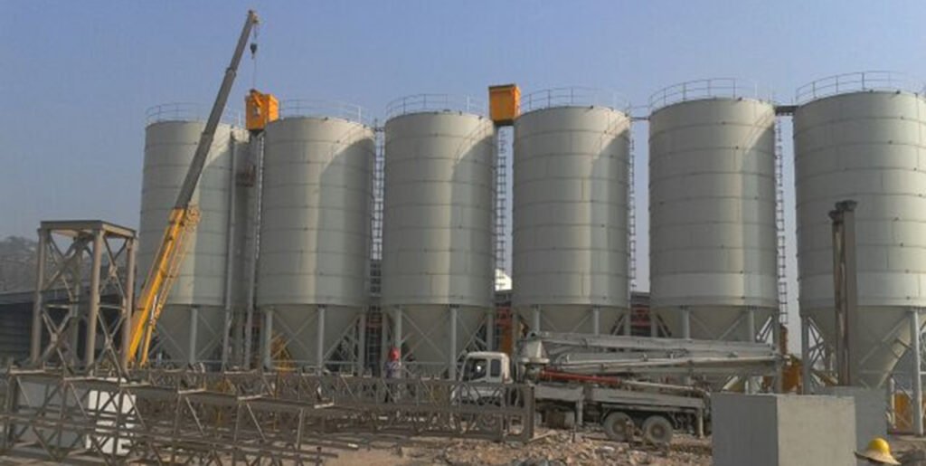
Ready-Mixed Concrete Production
Ready-mix concrete plants rely on high-capacity storage silos to ensure continuous batching cycles throughout the day. When integrated with automated batching systems, these high-capacity silos help maintain mixing precision and consistent throughput.
- Typical Configuration: 2–6 stationary cement silos, with a total capacity of 1,000–10,000 tons.
- Common Types: Large-capacity silos (bolted assembly or spiral-seam construction).
- Special Requirements: Compartmentalized silos designed for the simultaneous storage of different cement grades and admixtures.
On-site Concrete Production
Portable and mobile cement storage silos enable contractors to produce concrete directly at the job site. This reduces reliance on ready-mix delivery, avoids scheduling delays, and ensures that construction crews can pour concrete at any time.
- Typical Configuration: 1–3 mobile or low-profile cement silos, with a capacity of 50–200 tons each.
- Common Types: Circular portable or low-profile series.
- Special Requirements: Rapid deployment, no foundation required, and easy relocation.
Precast Component Manufacturing
Precast facilities rely on precise batching and high material availability. Multiple storage silos are typically utilized to store various powdered materials, thereby enhancing the flexibility of the mixing design.
- Typical Configuration: 3–5 stationary cement silos, with a total capacity of 500–5,000 tons.
- Common Type: Fully welded stationary silos.
- Special Requirements: High-precision material level control, integration with automated batching systems.
Infrastructure and Remote Projects
Projects such as bridges, tunnels, or utility infrastructure benefit from mobile storage silos, which support batching plants located in remote areas where ready-mix trucks are unable to provide continuous delivery.
- Typical Configuration: 2–4 mobile cement storage silos, with a capacity of 100–300 tons.
- Common Types: High-capacity mobile silos or tilt-silos.
- Special Requirements: Onboard generator, reliable material flow system.
Large-scale Commercial Buildings
High-rise, industrial, or multi-phase construction projects typically utilize on-site batching plants supported by storage silos to eliminate delays and enhance production capacity.
- Typical Configuration: 3–6 low-profile or mobile cement silos, with a total capacity of 300–1,000 tons.
- Common Type: Low-profile series (compliant with urban height restrictions).
- Special Requirements: High-efficiency dust removal system; compliance with urban environmental regulations.
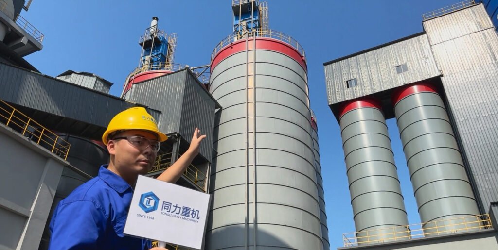
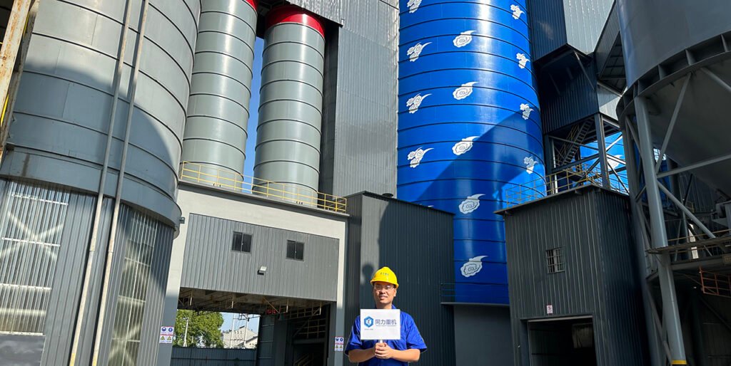
Cement Transfer Center
Serving as a key node within the cement distribution network, a cement transfer center utilizes large-capacity, stationary cement storage silos. Typically situated at ports, railway hubs, or major road junctions, these facilities feature individual silo capacities ranging from 5,000 to 100,000 tons, with total storage capacities potentially reaching hundreds of thousands of tons. The transfer center distributes cement to surrounding commercial concrete plants, precast concrete factories, and construction sites via bulk cement tankers. Furthermore, the center's storage silos interface directly with the bulk dispatch systems of cement production lines, thereby ensuring a seamless transition of cement from production through to distribution.
Procurement Decision Framework for Cement Storage Silos
Selecting the appropriate storage silo requires an understanding of material requirements, site conditions, and production objectives. The key purchasing considerations are as follows:
- Capacity Requirements: Capacity is measured in cubic feet or barrels. The objective is to size the storage silo such that production is never interrupted due to the need for replenishment. An undersized silo leads to downtime, whereas an oversized silo incurs higher costs and occupies excess space.
- Mobility vs. Permanence: Construction sites requiring frequent relocation benefit from mobile or low-profile units. Established ready-mix or precast concrete facilities typically opt for large, stationary silos equipped with integrated blowers and dust collectors.
- Discharge Requirements: The size and speed of the auger determine the rate at which cement reaches the mixer. Facilities utilizing high-throughput mixers require rapid, continuous discharge capabilities.
- Material Flow Technology: Aeration pads, vibrators, hopper design, and internal coatings all influence the ease with which cement flows. Blended cements or fly ash may necessitate more robust flow-assistance systems.
- Dust Control and Environmental Compliance: Dust collectors, baghouses, and sealed filling systems are critical for maintaining clean operations. Local municipal regulations may mandate specific levels of dust control.
- Compatibility with Batch Plants: The storage silo must align—both physically and functionally—with the existing batch plant, mixer, and screw conveyors. Factors such as height, angle, and discharge location are paramount.
- Power and Air Requirements: Air compressors, blowers, and aeration systems require a stable supply of electricity and compressed air. Remote job sites necessitate reliable generators or integrated power storage systems.
- Maintenance and Reliability: Cement storage silos require periodic inspection to ensure proper material flow, prevent contamination, and protect the equipment. Preventive maintenance minimizes downtime and shields the batch plant from unplanned interruptions, particularly on high-volume job sites.
- System Compatibility: The control system for the cement storage silo should feature standard communication interfaces, enabling seamless data exchange with the upstream cement production line's DCS (Distributed Control System) or the downstream concrete batching plant's control system. This facilitates unified scheduling and management across the entire production chain.
Maintenance, Management, and Safe Operation Guidelines
Preventive Maintenance System
Establishing a system of regular preventive maintenance is key to ensuring the long-term, reliable operation of the cement storage silo. The specific maintenance items and their corresponding cycles are as follows:
- Weekly: Inspect the operating status of the fluidization system and vibrators to confirm the absence of abnormal noise or vibration; check the dust collector's differential pressure to determine if the filter elements are clogged.
- Monthly: Lubricate the bearings and gearboxes of the screw conveyor, and inspect the condition of seals for wear; check the responsiveness of the pressure/vacuum relief valves.
- Quarterly: Clean the dust collector filter elements; inspect the tightness of all seals on the silo structure; check the wiring and insulation of the electrical system.
- Semi-annually: Calibrate the material level indicators to ensure measurement accuracy; check the oil level and pressure of the air compressor.
- Annually: Enter the silo to conduct a comprehensive internal inspection; remove accumulated material from the silo walls and hopper; inspect the silo structure for signs of corrosion.
- During the Rainy Season: Intensify humidity monitoring inside the silo; inspect the waterproofing seals on the roof and flanges; increase the activation frequency of the fluidization system to prevent the material from absorbing moisture and caking.
Safe Operating Procedures
- Operators must undergo professional training and be thoroughly familiar with the equipment's structure and operating procedures.
- Before entering the silo to perform work, all power supplies to the equipment must be disconnected, and adequate ventilation and gas testing must be conducted.
- When entering the silo, personnel must wear appropriate personal protective equipment, including dust masks, safety helmets, and safety harnesses.
- During operations inside the silo, a designated safety monitor must remain stationed outside to maintain constant communication.
- Smoking and the use of open flames inside the silo are strictly prohibited.
- Safety devices—such as pressure relief valves and emergency stop buttons—must be inspected regularly to ensure their proper functioning.
- During filling operations, the rated capacity of the silo must strictly not be exceeded.
- Prior to relocating a mobile cement storage silo, the contents of the silo must be completely emptied, and the condition of the travel mechanism, braking system, and lighting fixtures must be thoroughly inspected.
Common Troubleshooting
- Material Bridging: Activate the vibrator and fluidization system; check the aeration pads for blockages and manually clear them if necessary.
- Material Caking: Enhance the silo's sealing to prevent rainwater ingress; periodically activate the fluidization system to clear accumulated material inside the silo.
- Excessive Dust Emissions: Replace the dust collector filter cartridges; inspect the silo's seals; and adjust the filling rate.
- Inaccurate Level Indication: Calibrate the sensors; clean any material buildup adhering to the probe surfaces.
- Screw Conveyor Blockage: Shut down the equipment and cut off the power supply; clear the material from inside the conveyor; and check the material's moisture content and the effectiveness of the fluidization.
- Abnormal Silo Pressure: Verify that the pressure/vacuum relief valve is functioning correctly; check the dust collector for blockages.
Equipment Warranty Policy
The warranty policy for cement storage silos is typically categorized into two types: non-commercial use and commercial use. Specific terms should be confirmed directly with the equipment supplier. For components not manufactured by the equipment manufacturer (such as motors, tires, batteries, etc.), the warranty policy of the original component manufacturer applies. For detailed warranty information, please consult an authorized dealer or refer to the equipment user manual.
Conclusion
The cement storage silo serves as a core component within modern concrete production systems, while also acting as a critical interface connecting the cement production line with downstream concrete application processes; consequently, its technological evolution is inextricably linked to transformative shifts in the construction industry's production paradigms. Based on mobility, silos can be categorized into fixed, portable circular, low-profile, and tilt-type variants; structurally, they are classified as vertical, horizontal, or compartmentalized; and in terms of construction method, they fall into welded, bolted-assembly, or spiral-folded types. Each type of cement storage silo possesses distinct technical parameters and is suited to specific operational contexts; therefore, engineering selection requires a comprehensive assessment of various factors, including capacity requirements, mobility needs, site conditions, material characteristics, and system compatibility. The operational reliability of a cement storage silo is contingent upon both the design quality of its core systems and the standard of its daily maintenance and management. Its core technologies—such as pneumatic conveying, fluidization, and dust removal—share a high degree of commonality with the technologies employed in cement production lines, thereby facilitating the standardization of equipment and the integration of systems across the entire cement supply chain. Establishing a robust preventive maintenance regimen and adhering to strict safety operating procedures can effectively extend the service life of the equipment and significantly reduce the incidence of operational failures.
No. Cement storage silos are versatile, sealed storage vessels designed for powdery materials. In addition to cement, they can safely store a variety of other construction-related powders, such as fly ash, lime, and ground granulated blast furnace slag (GGBFS). However, it is crucial to note that before switching to store a different type of material, the interior of the silo must be thoroughly cleaned to prevent cross-contamination and ensure product quality.
Most mobile cement storage silos do not require a permanent poured concrete foundation. These units are typically equipped with heavy-duty skid bases or steel frames, allowing them to be placed directly on level, compacted, and hardened ground or on a gravel surface. However, for larger mobile silos with capacities exceeding 200 tons—or for sites where the ground's load-bearing capacity is insufficient—it is recommended to lay simple concrete strip footings to enhance stability.
Under conditions that are well-sealed, dry, and well-ventilated, ordinary Portland cement can be stored for 3 to 6 months. After this period, the cement's hydration activity gradually declines, resulting in reduced strength performance. It is recommended to adhere to the "First-In, First-Out" (FIFO) inventory management principle and to regularly test the quality parameters of the stored cement to avoid using expired or deteriorated material.
Preventing caking and bridging requires a dual approach involving both design and operational measures. From a design perspective, the silo should feature a conical hopper with a 60-degree angle and be equipped with a sufficient number of pneumatic air pads and vibrators. Operationally, the silo must remain sealed to prevent rainwater ingress; additionally, the fluidization system should be activated periodically to loosen the material and prevent the cement from remaining static for extended periods. In cases where minor bridging has already occurred, the blockage can be cleared by alternately activating the vibrators and the fluidization system; under no circumstances should personnel enter the silo to manually clear the obstruction.
Dust emission control relies primarily on the use of dust removal systems and adherence to standardized operating procedures: all cement storage silos must be equipped with pulse-jet or bag-type dust collectors, with a filtration area appropriately matched to the silo's capacity. During filling operations, the conveying speed should be regulated to prevent sudden pressure surges within the silo. Dust collector filter elements must be cleaned and replaced periodically to ensure filtration efficiency, and all sealing points on the silo structure should be inspected to prevent dust leakage.